2004 DODGE TOWN AND COUNTRY low oil pressure
[x] Cancel search: low oil pressurePage 1196 of 2585
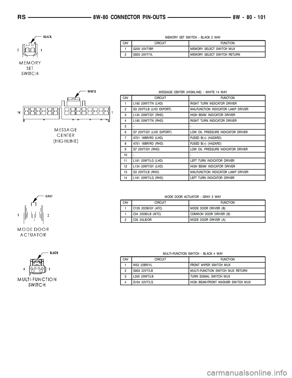
MEMORY SET SWITCH - BLACK 2 WAY
CAV CIRCUIT FUNCTION
1 G200 20VT/BR MEMORY SELECT SWITCH MUX
2 G920 20VT/YL MEMORY SELECT SWITCH RETURN
MESSAGE CENTER (HIGHLINE) - WHITE 14 WAY
CAV CIRCUIT FUNCTION
1 L160 20WT/TN (LHD) RIGHT TURN INDICATOR DRIVER
2 G3 20VT/LB (LHD EXPORT) MALFUNCTION INDICATOR LAMP DRIVER
3 L134 20WT/GY (RHD) HIGH BEAM INDICATOR DRIVER
4 L160 20WT/TN (RHD) RIGHT TURN INDICATOR DRIVER
5- -
6 G7 20VT/GY (LHD EXPORT) LOW OIL PRESSURE INDICATOR DRIVER
7 A701 18BR/RD (LHD) FUSED B(+) (HAZARD)
8 A701 18BR/RD (RHD) FUSED B(+) (HAZARD)
9 G7 20VT/GY (RHD) LOW OIL PRESSURE INDICATOR DRIVER
10 - -
11 L161 20WT/LG (LHD) LEFT TURN INDICATOR DRIVER
12 L134 20WT/GY (LHD) HIGH BEAM INDICATOR DRIVER
13 G3 20VT/LB (RHD) MALFUNCTION INDICATOR LAMP DRIVER
14 L161 20WT/LG (RHD) LEFT TURN INDICATOR DRIVER
MODE DOOR ACTUATOR - GRAY 2 WAY
CAV CIRCUIT FUNCTION
1 C135 20DB/GY (ATC) MODE DOOR DRIVER (B)
1 C34 20DB/LB (MTC) COMMON DOOR DRIVER (B)
2 C35 20LB/OR MODE DOOR DRIVER (A)
MULTI-FUNCTION SWITCH - BLACK 4 WAY
CAV CIRCUIT FUNCTION
1 W52 22BR/YL FRONT WIPER SWITCH MUX
2 G902 22VT/LB MULTI-FUNCTION SWITCH MUX RETURN
3 L305 20WT/LB TURN SIGNAL SWITCH MUX
4 G194 22VT/LG HIGH BEAM/FRONT WASHER SWITCH MUX
RS8W-80 CONNECTOR PIN-OUTS8W - 80 - 101
Page 1205 of 2585
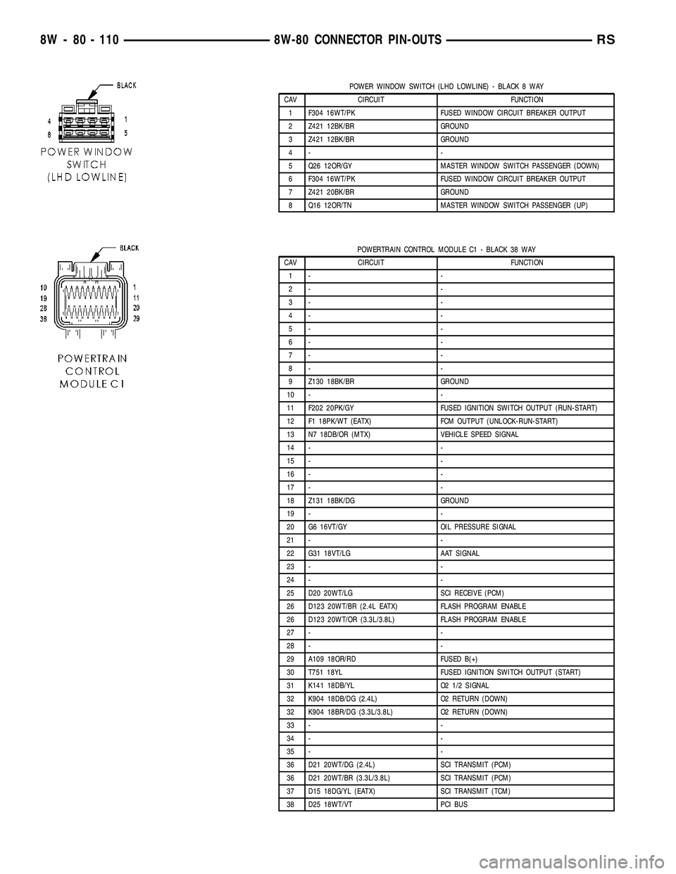
POWER WINDOW SWITCH (LHD LOWLINE) - BLACK 8 WAY
CAV CIRCUIT FUNCTION
1 F304 16WT/PK FUSED WINDOW CIRCUIT BREAKER OUTPUT
2 Z421 12BK/BR GROUND
3 Z421 12BK/BR GROUND
4- -
5 Q26 12OR/GY MASTER WINDOW SWITCH PASSENGER (DOWN)
6 F304 16WT/PK FUSED WINDOW CIRCUIT BREAKER OUTPUT
7 Z421 20BK/BR GROUND
8 Q16 12OR/TN MASTER WINDOW SWITCH PASSENGER (UP)
POWERTRAIN CONTROL MODULE C1 - BLACK 38 WAY
CAV CIRCUIT FUNCTION
1- -
2- -
3- -
4- -
5- -
6- -
7- -
8- -
9 Z130 18BK/BR GROUND
10 - -
11 F202 20PK/GY FUSED IGNITION SWITCH OUTPUT (RUN-START)
12 F1 18PK/WT (EATX) FCM OUTPUT (UNLOCK-RUN-START)
13 N7 18DB/OR (MTX) VEHICLE SPEED SIGNAL
14 - -
15 - -
16 - -
17 - -
18 Z131 18BK/DG GROUND
19 - -
20 G6 16VT/GY OIL PRESSURE SIGNAL
21 - -
22 G31 18VT/LG AAT SIGNAL
23 - -
24 - -
25 D20 20WT/LG SCI RECEIVE (PCM)
26 D123 20WT/BR (2.4L EATX) FLASH PROGRAM ENABLE
26 D123 20WT/OR (3.3L/3.8L) FLASH PROGRAM ENABLE
27 - -
28 - -
29 A109 18OR/RD FUSED B(+)
30 T751 18YL FUSED IGNITION SWITCH OUTPUT (START)
31 K141 18DB/YL O2 1/2 SIGNAL
32 K904 18DB/DG (2.4L) O2 RETURN (DOWN)
32 K904 18BR/DG (3.3L/3.8L) O2 RETURN (DOWN)
33 - -
34 - -
35 - -
36 D21 20WT/DG (2.4L) SCI TRANSMIT (PCM)
36 D21 20WT/BR (3.3L/3.8L) SCI TRANSMIT (PCM)
37 D15 18DG/YL (EATX) SCI TRANSMIT (TCM)
38 D25 18WT/VT PCI BUS
8W - 80 - 110 8W-80 CONNECTOR PIN-OUTSRS
Page 1236 of 2585
CONNECTOR NAME/NUMBER COLOR LOCATION FIG.
Engine Control Module C2
(Diesel)BK Right Side of Engine N/S
Engine Coolant Temp Sensor
(Gas)BK On Cylinder Block N/S
Engine Coolant Temp Sensor
(Diesel)BL On Cylinder Block 15
Engine Oil Pressure Sensor
(Diesel)BK Rear of Engine 16
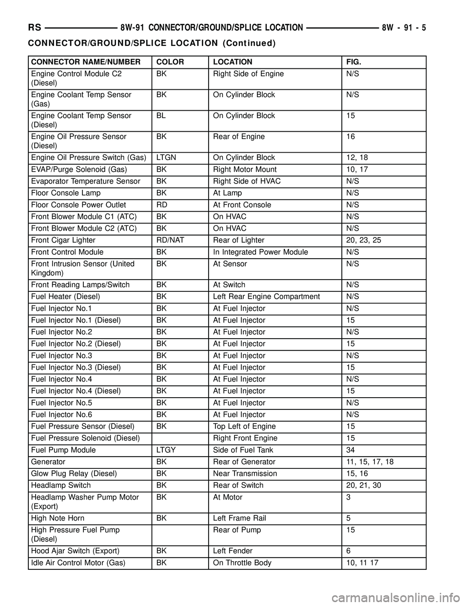
Engine Oil Pressure Switch (Gas) LTGN On Cylinder Block 12, 18
EVAP/Purge Solenoid (Gas) BK Right Motor Mount 10, 17
Evaporator Temperature Sensor BK Right Side of HVAC N/S
Floor Console Lamp BK At Lamp N/S
Floor Console Power Outlet RD At Front Console N/S
Front Blower Module C1 (ATC) BK On HVAC N/S
Front Blower Module C2 (ATC) BK On HVAC N/S
Front Cigar Lighter RD/NAT Rear of Lighter 20, 23, 25
Front Control Module BK In Integrated Power Module N/S
Front Intrusion Sensor (United
Kingdom)BK At Sensor N/S
Front Reading Lamps/Switch BK At Switch N/S
Fuel Heater (Diesel) BK Left Rear Engine Compartment N/S
Fuel Injector No.1 BK At Fuel Injector N/S
Fuel Injector No.1 (Diesel) BK At Fuel Injector 15
Fuel Injector No.2 BK At Fuel Injector N/S
Fuel Injector No.2 (Diesel) BK At Fuel Injector 15
Fuel Injector No.3 BK At Fuel Injector N/S
Fuel Injector No.3 (Diesel) BK At Fuel Injector 15
Fuel Injector No.4 BK At Fuel Injector N/S
Fuel Injector No.4 (Diesel) BK At Fuel Injector 15
Fuel Injector No.5 BK At Fuel Injector N/S
Fuel Injector No.6 BK At Fuel Injector N/S
Fuel Pressure Sensor (Diesel) BK Top Left of Engine 15
Fuel Pressure Solenoid (Diesel) Right Front Engine 15
Fuel Pump Module LTGY Side of Fuel Tank 34
Generator BK Rear of Generator 11, 15, 17, 18
Glow Plug Relay (Diesel) BK Near Transmission 15, 16
Headlamp Switch BK Rear of Switch 20, 21, 30
Headlamp Washer Pump Motor
(Export)BK At Motor 3
High Note Horn BK Left Frame Rail 5
High Pressure Fuel Pump
(Diesel)Rear of Pump 15
Hood Ajar Switch (Export) BK Left Fender 6
Idle Air Control Motor (Gas) BK On Throttle Body 10, 11 17
RS8W-91 CONNECTOR/GROUND/SPLICE LOCATION8W-91-5
CONNECTOR/GROUND/SPLICE LOCATION (Continued)
Page 1299 of 2585
REMOVAL - CYLINDER HEAD OFF........32
INSPECTION..........................32
INSTALLATION
INSTALLATION - CYLINDER HEAD ON.....33
INSTALLATION - CYLINDER HEAD OFF....33
HYDRAULIC LASH ADJUSTERS
DIAGNOSIS AND TESTING - HYDRAULIC
LASH ADJUSTER NOISE DIAGNOSIS......34
REMOVAL.............................34
INSTALLATION.........................34
ROCKER ARMS
REMOVAL.............................34
INSPECTION..........................35
INSTALLATION.........................35
ENGINE BLOCK
DESCRIPTION.........................35
STANDARD PROCEDURE - CYLINDER BORE
HONING............................35
CLEANING............................36
INSPECTION..........................36
CRANKSHAFT
STANDARD PROCEDURE - CRANKSHAFT
ENDPLAY ...........................36
REMOVAL - CRANKSHAFT................37
INSPECTION..........................37
INSTALLATION - CRANKSHAFT............38
CRANKSHAFT OIL SEAL - FRONT
REMOVAL.............................40
INSTALLATION.........................40
CRANKSHAFT OIL SEAL - REAR
REMOVAL.............................41
INSTALLATION.........................42
PISTON & CONNECTING ROD
DESCRIPTION.........................42
STANDARD PROCEDURE - PISTON TO
CYLINDER BORE FITTING..............42
REMOVAL.............................43
INSTALLATION.........................44
CONNECTING ROD BEARINGS
STANDARD PROCEDURE
CONNECTING ROD - FITTING...........45
PISTON RINGS
STANDARD PROCEDURE
PISTON RING - FITTING................45
REMOVAL.............................46
INSTALLATION.........................46
VIBRATION DAMPER
REMOVAL.............................47
INSTALLATION.........................47
STRUCTURAL COLLAR
REMOVAL.............................47
INSTALLATION.........................48
ENGINE MOUNTING
DESCRIPTION.........................48
FRONT MOUNT
REMOVAL.............................49
INSTALLATION.........................49LEFT MOUNT
REMOVAL.............................49
INSTALLATION.........................50
REAR MOUNT
REMOVAL.............................50
INSTALLATION.........................50
RIGHT MOUNT
REMOVAL.............................51
INSTALLATION.........................51
LUBRICATION
DESCRIPTION.........................52
OPERATION...........................52
DIAGNOSIS AND TESTING - CHECKING
ENGINE OIL PRESSURE................52
OIL
STANDARD PROCEDURE
ENGINE OIL LEVEL CHECK.............53
STANDARD PROCEDURE - ENGINE OIL
AND FILTER CHANGE..................53
OIL FILTER
DESCRIPTION.........................53
REMOVAL.............................53
INSTALLATION.........................53
OIL PAN
REMOVAL.............................54
INSTALLATION.........................54
OIL PRESSURE SWITCH
REMOVAL.............................54
INSTALLATION.........................54
OIL PUMP
REMOVAL.............................55
DISASSEMBLY.........................55
CLEANING............................56
INSPECTION..........................56
ASSEMBLY............................56
INSTALLATION.........................57
INTAKE MANIFOLD
DESCRIPTION.........................58
DIAGNOSIS AND TESTING - INTAKE
MANIFOLD LEAKS.....................58
INTAKE MANIFOLD - UPPER
REMOVAL.............................58
INSPECTION..........................59
INSTALLATION.........................59
INTAKE MANIFOLD - LOWER
REMOVAL.............................60
INSPECTION..........................60
INSTALLATION.........................60
EXHAUST MANIFOLD
REMOVAL.............................61
CLEANING............................61
INSPECTION..........................61
INSTALLATION.........................61
TIMING BELT COVER(S)
REMOVAL.............................61
INSTALLATION.........................62
9 - 2 ENGINE 2.4LRS
Page 1300 of 2585
TIMING BELT AND SPROCKET(S)
REMOVAL
REMOVAL - TIMING BELT...............63
REMOVAL - CAMSHAFT SPROCKETS.....64
REMOVAL - CRANKSHAFT SPROCKET....64
CLEANING............................64
INSTALLATION
INSTALLATION - CRANKSHAFT SPROCKET . 65
INSTALLATION - CAMSHAFT SPROCKETS . . 65INSTALLATION - TIMING BELT...........65
TIMING BELT TENSIONER & PULLEY
REMOVAL.............................68
INSTALLATION.........................69
BALANCE SHAFTS AND CARRIER ASSEMBLY
DESCRIPTION.........................69
OPERATION...........................69
REMOVAL.............................69
INSTALLATION.........................72
ENGINE 2.4L
DESCRIPTION
The 2.4 Liter (148 cu. in.) in-line four cylinder
engine is a double over head camshaft with hydraulic
lash adjusters and four valve per cylinder design.
The engine is free-wheeling; meaning it has provi-
sions for piston-to-valve clearance. However valve-to-
valve interference can occur, if camshafts are rotated
independently.
The cylinders are numbered from front of the
engine to the rear. The firing order is 1±3±4±2.
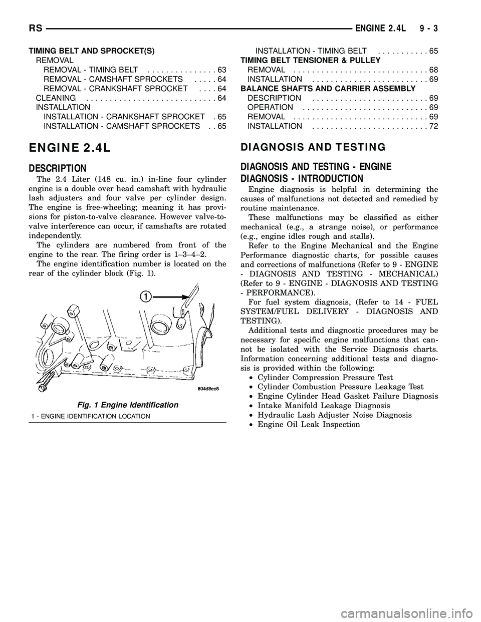
The engine identification number is located on the
rear of the cylinder block (Fig. 1).
DIAGNOSIS AND TESTING
DIAGNOSIS AND TESTING - ENGINE
DIAGNOSIS - INTRODUCTION
Engine diagnosis is helpful in determining the
causes of malfunctions not detected and remedied by
routine maintenance.
These malfunctions may be classified as either
mechanical (e.g., a strange noise), or performance
(e.g., engine idles rough and stalls).
Refer to the Engine Mechanical and the Engine
Performance diagnostic charts, for possible causes
and corrections of malfunctions (Refer to 9 - ENGINE
- DIAGNOSIS AND TESTING - MECHANICAL)
(Refer to 9 - ENGINE - DIAGNOSIS AND TESTING
- PERFORMANCE).
For fuel system diagnosis, (Refer to 14 - FUEL
SYSTEM/FUEL DELIVERY - DIAGNOSIS AND
TESTING).
Additional tests and diagnostic procedures may be
necessary for specific engine malfunctions that can-
not be isolated with the Service Diagnosis charts.
Information concerning additional tests and diagno-
sis is provided within the following:
²Cylinder Compression Pressure Test
²Cylinder Combustion Pressure Leakage Test
²Engine Cylinder Head Gasket Failure Diagnosis
²Intake Manifold Leakage Diagnosis
²Hydraulic Lash Adjuster Noise Diagnosis
²Engine Oil Leak Inspection
Fig. 1 Engine Identification
1 - ENGINE IDENTIFICATION LOCATION
RSENGINE 2.4L9-3
Page 1303 of 2585
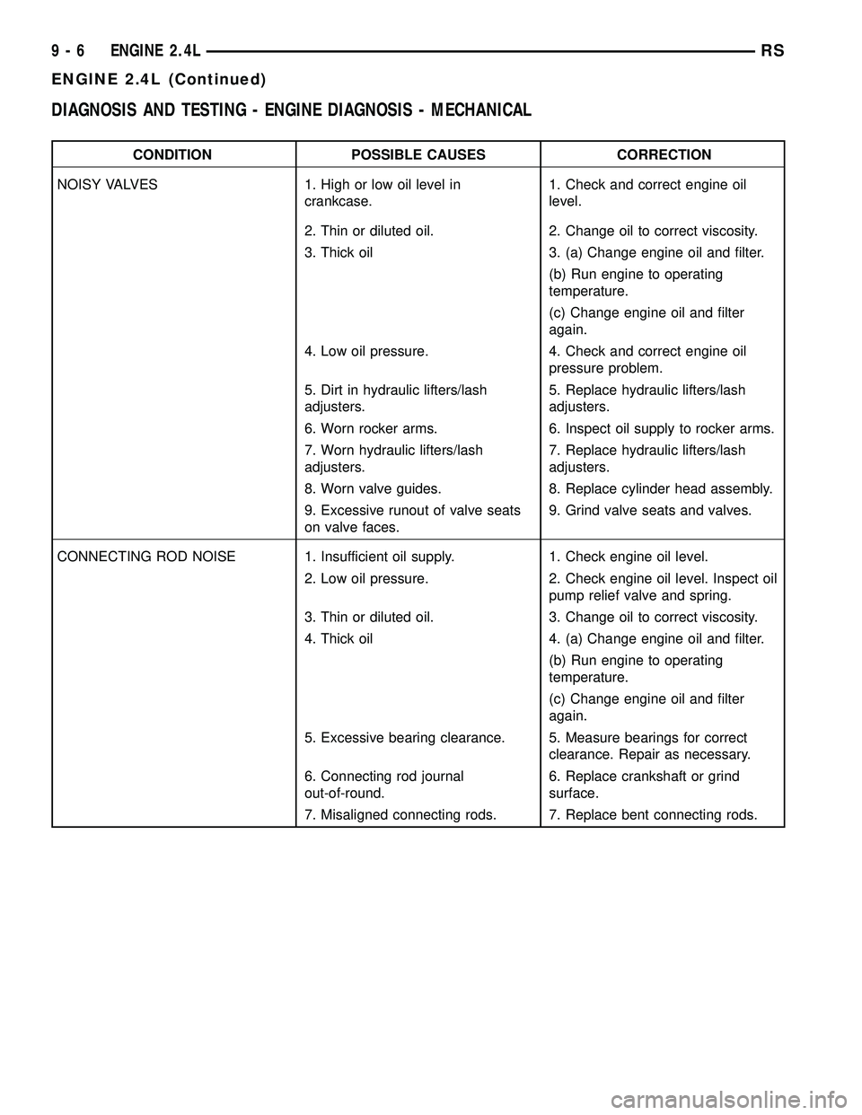
DIAGNOSIS AND TESTING - ENGINE DIAGNOSIS - MECHANICAL
CONDITION POSSIBLE CAUSES CORRECTION
NOISY VALVES 1. High or low oil level in
crankcase.1. Check and correct engine oil
level.
2. Thin or diluted oil. 2. Change oil to correct viscosity.
3. Thick oil 3. (a) Change engine oil and filter.
(b) Run engine to operating
temperature.
(c) Change engine oil and filter
again.
4. Low oil pressure. 4. Check and correct engine oil
pressure problem.
5. Dirt in hydraulic lifters/lash
adjusters.5. Replace hydraulic lifters/lash
adjusters.
6. Worn rocker arms. 6. Inspect oil supply to rocker arms.
7. Worn hydraulic lifters/lash
adjusters.7. Replace hydraulic lifters/lash
adjusters.
8. Worn valve guides. 8. Replace cylinder head assembly.
9. Excessive runout of valve seats
on valve faces.9. Grind valve seats and valves.
CONNECTING ROD NOISE 1. Insufficient oil supply. 1. Check engine oil level.
2. Low oil pressure. 2. Check engine oil level. Inspect oil
pump relief valve and spring.
3. Thin or diluted oil. 3. Change oil to correct viscosity.
4. Thick oil 4. (a) Change engine oil and filter.
(b) Run engine to operating
temperature.
(c) Change engine oil and filter
again.
5. Excessive bearing clearance. 5. Measure bearings for correct
clearance. Repair as necessary.
6. Connecting rod journal
out-of-round.6. Replace crankshaft or grind
surface.
7. Misaligned connecting rods. 7. Replace bent connecting rods.
9 - 6 ENGINE 2.4LRS
ENGINE 2.4L (Continued)
Page 1304 of 2585
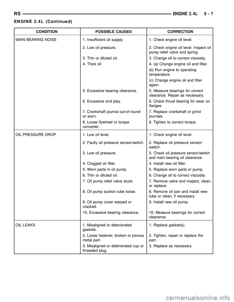
CONDITION POSSIBLE CAUSES CORRECTION
MAIN BEARING NOISE 1. Insufficient oil supply. 1. Check engine oil level.
2. Low oil pressure. 2. Check engine oil level. Inspect oil
pump relief valve and spring.
3. Thin or diluted oil. 3. Change oil to correct viscosity.
4. Thick oil 4. (a) Change engine oil and filter.
(b) Run engine to operating
temperature.
(c) Change engine oil and filter
again.
5. Excessive bearing clearance. 5. Measure bearings for correct
clearance. Repair as necessary.
6. Excessive end play. 6. Check thrust bearing for wear on
flanges.
7. Crankshaft journal out-of-round
or worn.7. Replace crankshaft or grind
journals.
8. Loose flywheel or torque
converter.8. Tighten to correct torque.
OIL PRESSURE DROP 1. Low oil level. 1. Check engine oil level.
2. Faulty oil pressure sensor/switch. 2. Replace oil pressure sensor/
switch.
3. Low oil pressure. 3. Check oil pressure sensor/switch
and main bearing oil clearance.
4. Clogged oil filter. 4. Install new oil filter.
5. Worn parts in oil pump. 5. Replace worn parts or pump.
6. Thin or diluted oil. 6. Change oil to correct viscosity.
7. Oil pump relief valve stuck. 7. Remove valve and inspect, clean,
or replace.
8. Oil pump suction tube loose. 8. Remove oil pan and install new
tube or clean, if necessary.
9. Oil pump cover warped or
cracked.9. Install new oil pump.
10. Excessive bearing clearance. 10. Measure bearings for correct
clearance.
OIL LEAKS 1. Misaligned or deteriorated
gaskets.1. Replace gasket(s).
2. Loose fastener, broken or porous
metal part.2. Tighten, repair or replace the
part.
3. Misaligned or deteriorated cup or
threaded plug.3. Replace as necessary.
RSENGINE 2.4L9-7
ENGINE 2.4L (Continued)
Page 1305 of 2585
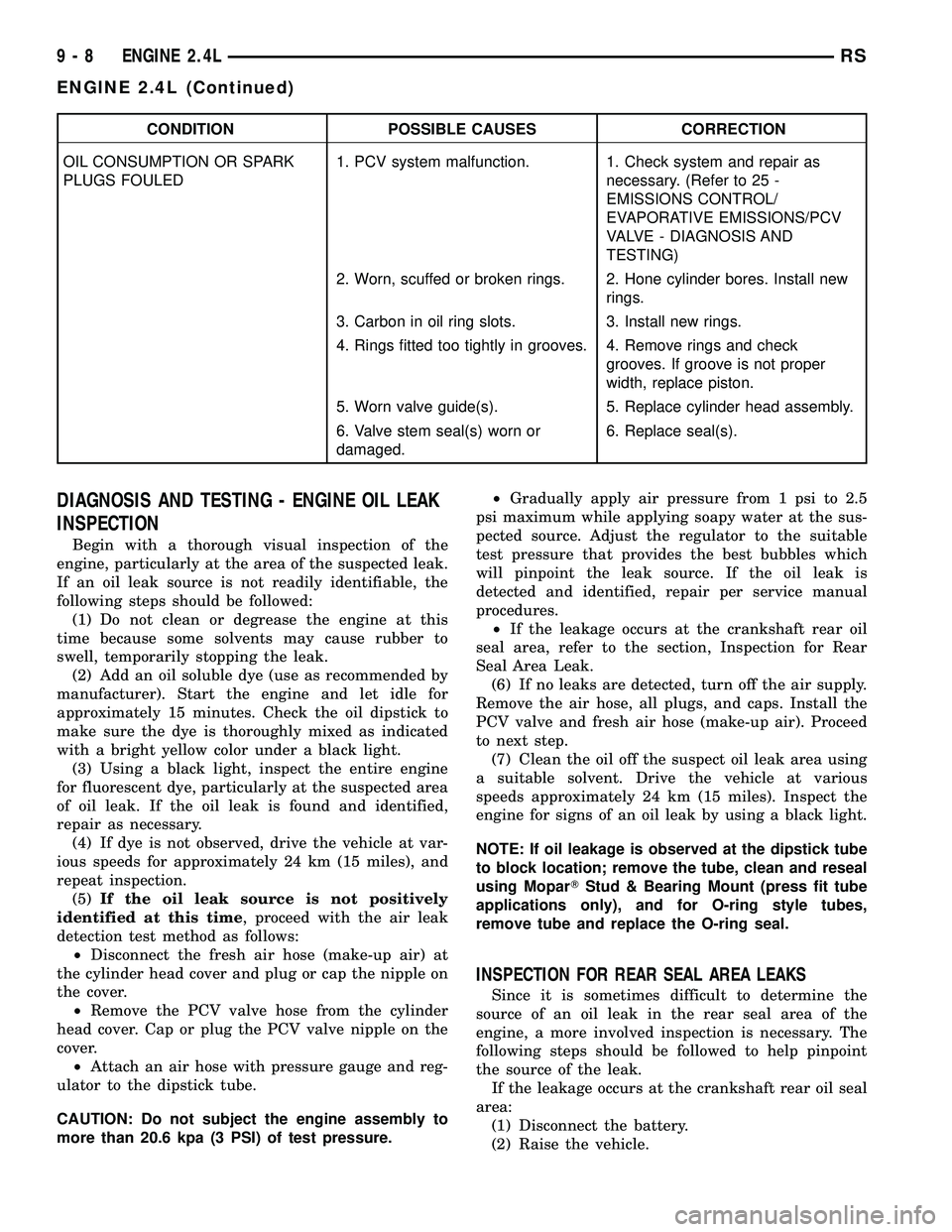
CONDITION POSSIBLE CAUSES CORRECTION
OIL CONSUMPTION OR SPARK
PLUGS FOULED1. PCV system malfunction. 1. Check system and repair as
necessary. (Refer to 25 -
EMISSIONS CONTROL/
EVAPORATIVE EMISSIONS/PCV
VALVE - DIAGNOSIS AND
TESTING)
2. Worn, scuffed or broken rings. 2. Hone cylinder bores. Install new
rings.
3. Carbon in oil ring slots. 3. Install new rings.
4. Rings fitted too tightly in grooves. 4. Remove rings and check
grooves. If groove is not proper
width, replace piston.
5. Worn valve guide(s). 5. Replace cylinder head assembly.
6. Valve stem seal(s) worn or
damaged.6. Replace seal(s).
DIAGNOSIS AND TESTING - ENGINE OIL LEAK
INSPECTION
Begin with a thorough visual inspection of the
engine, particularly at the area of the suspected leak.
If an oil leak source is not readily identifiable, the
following steps should be followed:
(1) Do not clean or degrease the engine at this
time because some solvents may cause rubber to
swell, temporarily stopping the leak.
(2) Add an oil soluble dye (use as recommended by
manufacturer). Start the engine and let idle for
approximately 15 minutes. Check the oil dipstick to
make sure the dye is thoroughly mixed as indicated
with a bright yellow color under a black light.
(3) Using a black light, inspect the entire engine
for fluorescent dye, particularly at the suspected area
of oil leak. If the oil leak is found and identified,
repair as necessary.
(4) If dye is not observed, drive the vehicle at var-
ious speeds for approximately 24 km (15 miles), and
repeat inspection.
(5)If the oil leak source is not positively
identified at this time, proceed with the air leak
detection test method as follows:
²Disconnect the fresh air hose (make-up air) at
the cylinder head cover and plug or cap the nipple on
the cover.
²Remove the PCV valve hose from the cylinder
head cover. Cap or plug the PCV valve nipple on the
cover.
²Attach an air hose with pressure gauge and reg-
ulator to the dipstick tube.
CAUTION: Do not subject the engine assembly to
more than 20.6 kpa (3 PSI) of test pressure.²Gradually apply air pressure from 1 psi to 2.5
psi maximum while applying soapy water at the sus-
pected source. Adjust the regulator to the suitable
test pressure that provides the best bubbles which
will pinpoint the leak source. If the oil leak is
detected and identified, repair per service manual
procedures.
²If the leakage occurs at the crankshaft rear oil
seal area, refer to the section, Inspection for Rear
Seal Area Leak.
(6) If no leaks are detected, turn off the air supply.
Remove the air hose, all plugs, and caps. Install the
PCV valve and fresh air hose (make-up air). Proceed
to next step.
(7) Clean the oil off the suspect oil leak area using
a suitable solvent. Drive the vehicle at various
speeds approximately 24 km (15 miles). Inspect the
engine for signs of an oil leak by using a black light.
NOTE: If oil leakage is observed at the dipstick tube
to block location; remove the tube, clean and reseal
using MoparTStud & Bearing Mount (press fit tube
applications only), and for O-ring style tubes,
remove tube and replace the O-ring seal.
INSPECTION FOR REAR SEAL AREA LEAKS
Since it is sometimes difficult to determine the
source of an oil leak in the rear seal area of the
engine, a more involved inspection is necessary. The
following steps should be followed to help pinpoint
the source of the leak.
If the leakage occurs at the crankshaft rear oil seal
area:
(1) Disconnect the battery.
(2) Raise the vehicle.
9 - 8 ENGINE 2.4LRS
ENGINE 2.4L (Continued)