2004 DODGE TOWN AND COUNTRY traction control
[x] Cancel search: traction controlPage 902 of 2585

8W-40 INSTRUMENT CLUSTER
Component Page
Airbag Control Module................ 8W-40-2
Body Control Module......... 8W-40-2, 3, 4, 5, 6,
7, 8, 9, 11, 12
Brake Fluid Level Switch.............. 8W-40-9
Clockspring........................ 8W-40-10
Controller Antilock Brake.......... 8W-40-10, 14
Engine Control Module.......... 8W-40-8, 10, 14
Engine Coolant Temp Sensor......... 8W-40-7, 8
Engine Oil Pressure Sensor........... 8W-40-14
Engine Oil Pressure Switch........... 8W-40-14
Front Control Module........ 8W-40-9, 10, 13, 14
Fuel Pump Module................... 8W-40-2
Fuse 24............................ 8W-40-2
G200..................... 8W-40-2, 11, 12, 13
G300.............................. 8W-40-9
Instrument Cluster........ 8W-40-2, 3, 4, 5, 6, 7,
8, 9, 11, 12, 13
Integrated Power Module........ 8W-40-2, 7, 8, 9,
10, 13, 14
Left Front Door Ajar Switch............ 8W-40-3
Left Front Door Lock Motor/Ajar Switch . . 8W-40-3Component Page
Left Sliding Door Control Module........ 8W-40-4
Left Sliding Door Latch Sensing Switch . . . 8W-40-4
Left Sliding Door Lock Motor/Ajar Switch . 8W-40-4
Left Speed Control Switch............ 8W-40-10
Liftgate Ajar Switch.................. 8W-40-3
Liftgate Cinch/Release Motor........... 8W-40-3
Message Center.................. 8W-40-6, 13
Multi-Function Switch................ 8W-40-6
Parking Brake Switch............. 8W-40-11, 12
Powertrain Control Module....... 8W-40-7, 10, 14
Right Front Door Ajar Switch........... 8W-40-3
Right Front Door Lock Motor/Ajar
Switch.......................... 8W-40-3
Right Sliding Door Control Module...... 8W-40-5
Right Sliding Door Latch Sensing Switch . . 8W-40-5
Right Sliding Door Lock Motor/Ajar
Switch.......................... 8W-40-5
Right Speed Control Switch........... 8W-40-10
Traction Control Switch............. 8W-40-7, 8
Vehicle Speed Sensor............... 8W-40-7, 8
Washer Fluid Level Switch............. 8W-40-9
RS8W-40 INSTRUMENT CLUSTER8W-40-1
Page 958 of 2585
8W-45 BODY CONTROL MODULE
Component Page
A/C-Heater Control............... 8W-45-16, 19
Auto Temp Control............... 8W-45-16, 19
Automatic Day/Night Mirror........... 8W-45-11
Body Control Module . . . 8W-45-2, 3, 4, 5, 6, 7, 8, 9,
10, 11, 12, 13, 15, 16, 17, 18, 19, 20
Cd Changer....................... 8W-45-17
Clockspring........................ 8W-45-17
Controller Antilock Brake............. 8W-45-13
Driver Door Courtesy Lamp........... 8W-45-15
Driver Door Lock Switch........... 8W-45-12, 15
Driver Heated Seat Module........... 8W-45-11
Dvd/Cd Changer.................... 8W-45-17
Floor Console Lamp................. 8W-45-13
Front Cigar Lighter................. 8W-45-17
Front Control Module................. 8W-45-3
Front Reading Lamps/Switch....... 8W-45-13, 15
Fuel Pump Module.................. 8W-45-15
Fuse 14............................ 8W-45-3
Fuse 19............................ 8W-45-2
Fuse 20............................ 8W-45-2
Fuse 24............................ 8W-45-2
G301............................ 8W-45-2, 8
Headlamp Switch............. 8W-45-11, 16, 20
Hood Ajar Switch................... 8W-45-12
Ignition Switch...................... 8W-45-3
Instrument Cluster.......... 8W-45-2, 16, 18, 19
Instrument Panel Switch Bank . . 8W-45-10, 11, 17,
19
Integrated Power Module..... 8W-45-2, 3, 5, 6, 13
Left B-Pillar Switch.................. 8W-45-9
Left Cylinder Lock Switch............ 8W-45-10
Left Front Door Ajar Switch............ 8W-45-9
Left Front Door Lock Motor/Ajar
Switch........................ 8W-45-7, 9
Left Liftgate Flood Lamp............. 8W-45-12
Left Mid Reading Lamp............ 8W-45-9, 14
Left Power Mirror................... 8W-45-20
Left Rear Lamp Assembly........... 8W-45-5, 6
Left Rear Reading Lamp........... 8W-45-9, 14
Left Remote Radio Switch............ 8W-45-17
Left Repeater Lamp................. 8W-45-20
Left Sliding Door Control Module..... 8W-45-8, 10
Left Sliding Door Lock Motor........... 8W-45-7Component Page
Left Sliding Door Lock Motor/Ajar
Switch........................ 8W-45-7, 8
Left Visor/Vanity Lamp.............. 8W-45-13
License Lamp....................... 8W-45-8
Liftgate Ajar Switch................. 8W-45-12
Liftgate Cinch/Release Motor.......... 8W-45-12
Memory Set Switch.................. 8W-45-4
Message Center.................... 8W-45-18
Multi-Function Switch............... 8W-45-16
Name Brand Speaker Relay............ 8W-45-3
Overhead Console................. 8W-45-4, 11
Passenger Door Courtesy Lamp........ 8W-45-15
Passenger Door Lock Switch........ 8W-45-12, 15
Passenger Folding Mirror Relay........ 8W-45-20
Passenger Heated Seat Module........ 8W-45-11
Power Folding Mirror Switch.......... 8W-45-20
Power Liftgate Module............. 8W-45-8, 12
Radio............................ 8W-45-17
Rear Auto Temp Control Switch..... 8W-45-10, 19
Rear Blower Rear Control Switch....... 8W-45-10
Rear Dome Lamp.................... 8W-45-9
Rear Wiper Motor.................... 8W-45-8
Right B-Pillar Switch................. 8W-45-9
Right Cylinder Lock Switch........... 8W-45-10
Right Front Door Ajar Switch........... 8W-45-9
Right Front Door Lock Motor/Ajar
Switch........................ 8W-45-7, 9
Right Liftgate Flood Lamp............ 8W-45-12
Right Mid Reading Lamp........... 8W-45-9, 14
Right Power Mirror................. 8W-45-20
Right Rear Lamp Assembly.......... 8W-45-5, 6
Right Rear Reading Lamp.......... 8W-45-9, 14
Right Remote Radio Switch........... 8W-45-17
Right Repeater Lamp................ 8W-45-20
Right Sliding Door Control Module.... 8W-45-8, 10
Right Sliding Door Lock Motor.......... 8W-45-7
Right Sliding Door Lock Motor/Ajar
Switch........................ 8W-45-7, 8
Right Visor/Vanity Lamp............. 8W-45-13
Sentry Key Remote Entry Module....... 8W-45-3
Thatcham Alarm Module............. 8W-45-10
Traction Control Switch.............. 8W-45-17
Trailer Tow Connector................ 8W-45-5
RS8W-45 BODY CONTROL MODULE8W-45-1
Page 1100 of 2585
Component Page
Right Front Door Lock Motor/Ajar Switch (Except
Base).......................... 8W-80-122
Right Front Impact Sensor (Except
Export)........................ 8W-80-122
Right Front Park/Turn Signal Lamp (Except
Export)........................ 8W-80-123
Right Front Wheel Speed Sensor...... 8W-80-123
Right Full Open Switch (Power Sliding
Door).......................... 8W-80-123
Right Headlamp (Except Export)...... 8W-80-123
Right Headlamp Leveling Motor
(Export)....................... 8W-80-124
Right High Beam Lamp (Export)...... 8W-80-124
Right Instrument Panel Speaker...... 8W-80-124
Right Liftgate Flood Lamp........... 8W-80-124
Right Low Beam Lamp (Export)....... 8W-80-125
Right Mid Reading Lamp (Premium/
Luxury)........................ 8W-80-125
Right Park Lamp (Export)........... 8W-80-125
Right Power Mirror................ 8W-80-125
Right Rear Lamp Assembly.......... 8W-80-126
Right Rear Pillar Speaker........... 8W-80-126
Right Rear Reading Lamp (Luxury).... 8W-80-126
Right Rear Speaker (Lowline)......... 8W-80-126
Right Rear Speaker (Highline)........ 8W-80-127
Right Rear Vent Motor.............. 8W-80-127
Right Rear Wheel Speed Sensor....... 8W-80-127
Right Remote Radio Switch.......... 8W-80-127
Right Repeater Lamp (Export)........ 8W-80-128
Right Seat Airbag.................. 8W-80-128
Right Side Impact Sensor 1 (Premium
ORC).......................... 8W-80-128
Right Sliding Door Control Module C1 (Power
Sliding Door)................... 8W-80-128Component Page
Right Sliding Door Control Module C2 (Power
Sliding Door)................... 8W-80-129
Right Sliding Door Latch Sensing Switch (Power
Sliding Door)................... 8W-80-129
Right Sliding Door Lock Motor (Power Sliding
Door).......................... 8W-80-129
Right Sliding Door Lock Motor/Ajar Switch (Manual
Sliding Door)................... 8W-80-130
Right Sliding Door Motor (Power Sliding
Door).......................... 8W-80-130
Right Speed Control Switch.......... 8W-80-130
Right Turn Signal Lamp (Export)...... 8W-80-130
Right Visor/Vanity Lamp (Premium/Luxury Except
Export)........................ 8W-80-131
Sentry Key Remote Entry Module
(SKREEM)..................... 8W-80-131
Siren (United Kingdom)............. 8W-80-131
Speed Control Servo (Gas)........... 8W-80-131
Sunroof Module (Except Export)....... 8W-80-132
Sunroof Switch (Except Export)....... 8W-80-132
Thatcham Alarm Module (United
Kingdom)...................... 8W-80-132
Throttle Position Sensor (Gas)........ 8W-80-133
Traction Control Switch............. 8W-80-133
Trailer Tow Connector (Except Export) . . 8W-80-133
Transmission Range Sensor.......... 8W-80-133
Transmission Solenoid/Pressure Switch
Assembly...................... 8W-80-134
Vehicle Speed Sensor (MTX).......... 8W-80-134
Washer Fluid Level Switch........... 8W-80-134
Washer Pump Motor................ 8W-80-134
Water In Fuel Sensor (Diesel)......... 8W-80-135
Wiper Module..................... 8W-80-135
RS8W-80 CONNECTOR PIN-OUTS8W-80-5
Page 1112 of 2585
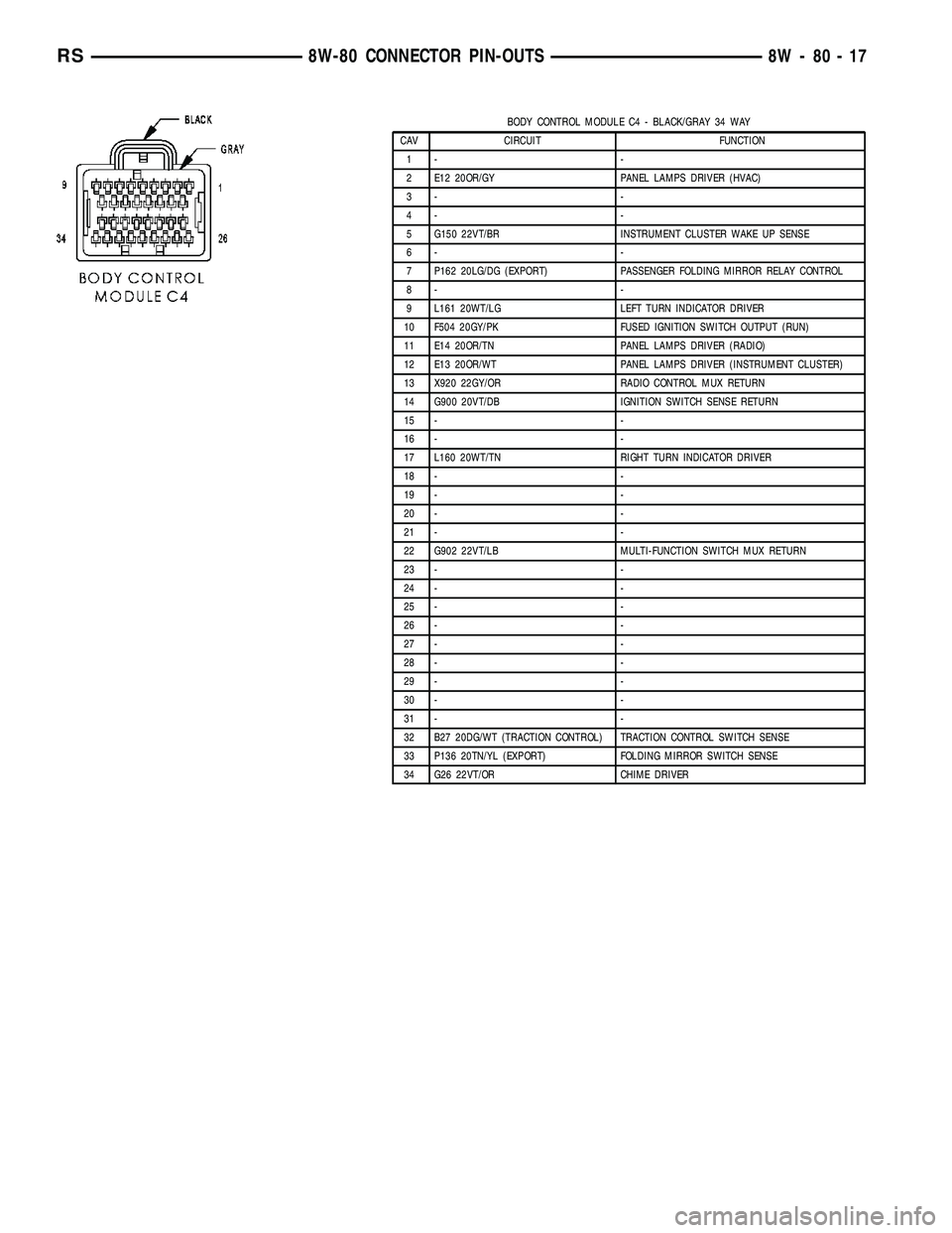
BODY CONTROL MODULE C4 - BLACK/GRAY 34 WAY
CAV CIRCUIT FUNCTION
1- -
2 E12 20OR/GY PANEL LAMPS DRIVER (HVAC)
3- -
4- -
5 G150 22VT/BR INSTRUMENT CLUSTER WAKE UP SENSE
6- -
7 P162 20LG/DG (EXPORT) PASSENGER FOLDING MIRROR RELAY CONTROL
8- -
9 L161 20WT/LG LEFT TURN INDICATOR DRIVER
10 F504 20GY/PK FUSED IGNITION SWITCH OUTPUT (RUN)
11 E14 20OR/TN PANEL LAMPS DRIVER (RADIO)
12 E13 20OR/WT PANEL LAMPS DRIVER (INSTRUMENT CLUSTER)
13 X920 22GY/OR RADIO CONTROL MUX RETURN
14 G900 20VT/DB IGNITION SWITCH SENSE RETURN
15 - -
16 - -
17 L160 20WT/TN RIGHT TURN INDICATOR DRIVER
18 - -
19 - -
20 - -
21 - -
22 G902 22VT/LB MULTI-FUNCTION SWITCH MUX RETURN
23 - -
24 - -
25 - -
26 - -
27 - -
28 - -
29 - -
30 - -
31 - -
32 B27 20DG/WT (TRACTION CONTROL) TRACTION CONTROL SWITCH SENSE
33 P136 20TN/YL (EXPORT) FOLDING MIRROR SWITCH SENSE
34 G26 22VT/OR CHIME DRIVER
RS8W-80 CONNECTOR PIN-OUTS8W-80-17
Page 1228 of 2585
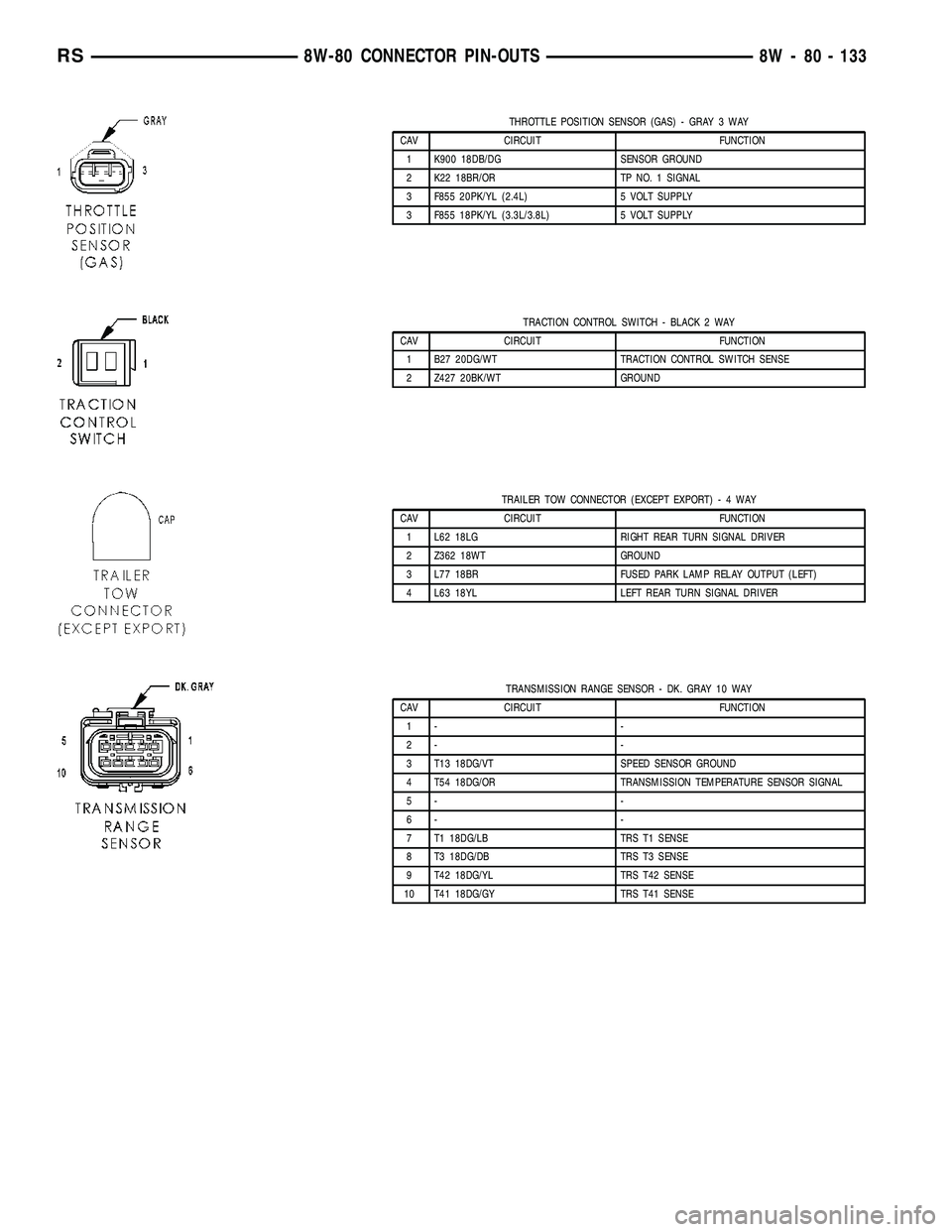
THROTTLE POSITION SENSOR (GAS) - GRAY 3 WAY
CAV CIRCUIT FUNCTION
1 K900 18DB/DG SENSOR GROUND
2 K22 18BR/OR TP NO. 1 SIGNAL
3 F855 20PK/YL (2.4L) 5 VOLT SUPPLY
3 F855 18PK/YL (3.3L/3.8L) 5 VOLT SUPPLY
TRACTION CONTROL SWITCH - BLACK 2 WAY
CAV CIRCUIT FUNCTION
1 B27 20DG/WT TRACTION CONTROL SWITCH SENSE
2 Z427 20BK/WT GROUND
TRAILER TOW CONNECTOR (EXCEPT EXPORT)-4WAY
CAV CIRCUIT FUNCTION
1 L62 18LG RIGHT REAR TURN SIGNAL DRIVER
2 Z362 18WT GROUND
3 L77 18BR FUSED PARK LAMP RELAY OUTPUT (LEFT)
4 L63 18YL LEFT REAR TURN SIGNAL DRIVER
TRANSMISSION RANGE SENSOR - DK. GRAY 10 WAY
CAV CIRCUIT FUNCTION
1- -
2- -
3 T13 18DG/VT SPEED SENSOR GROUND
4 T54 18DG/OR TRANSMISSION TEMPERATURE SENSOR SIGNAL
5- -
6- -
7 T1 18DG/LB TRS T1 SENSE
8 T3 18DG/DB TRS T3 SENSE
9 T42 18DG/YL TRS T42 SENSE
10 T41 18DG/GY TRS T41 SENSE
RS8W-80 CONNECTOR PIN-OUTS8W - 80 - 133
Page 1243 of 2585
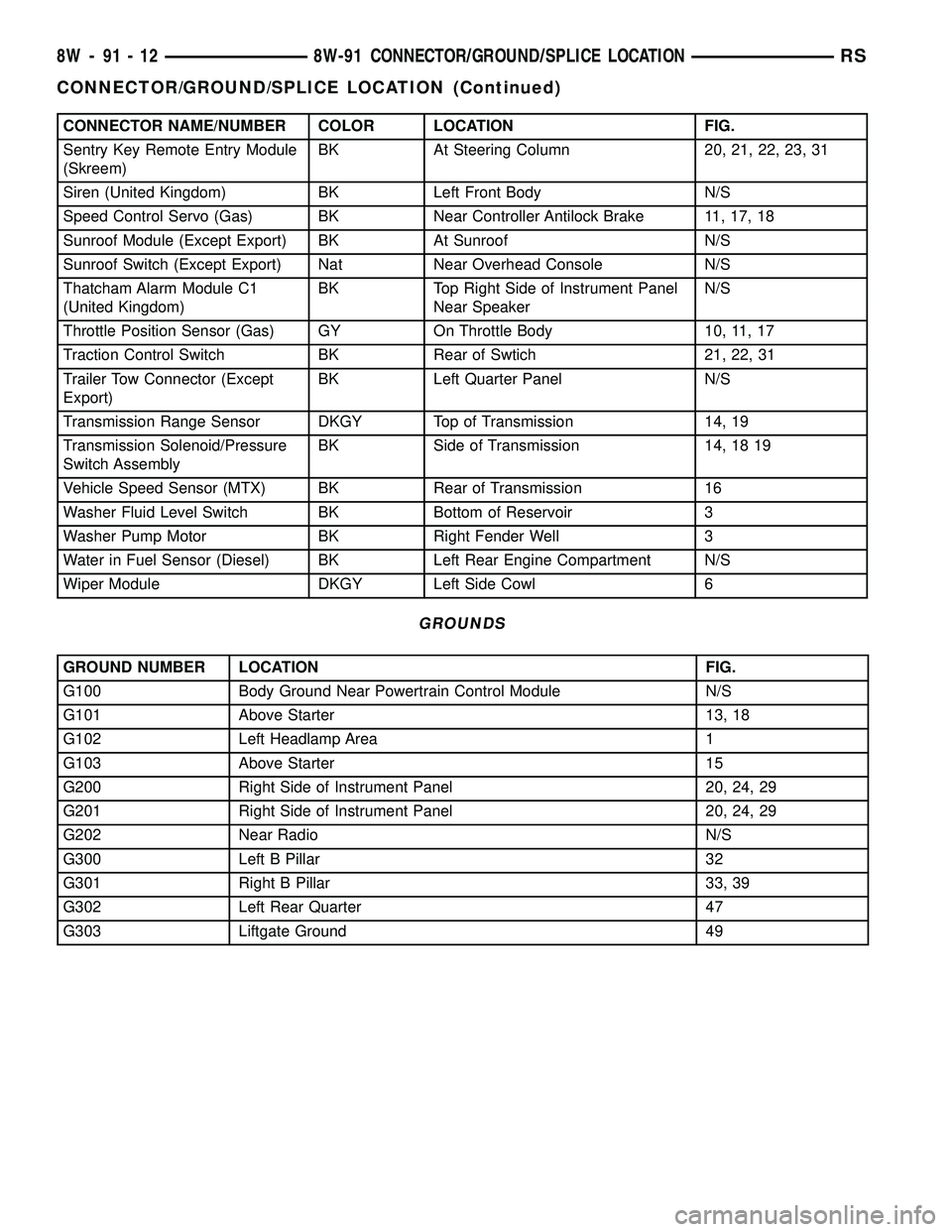
CONNECTOR NAME/NUMBER COLOR LOCATION FIG.
Sentry Key Remote Entry Module
(Skreem)BK At Steering Column 20, 21, 22, 23, 31
Siren (United Kingdom) BK Left Front Body N/S
Speed Control Servo (Gas) BK Near Controller Antilock Brake 11, 17, 18
Sunroof Module (Except Export) BK At Sunroof N/S
Sunroof Switch (Except Export) Nat Near Overhead Console N/S
Thatcham Alarm Module C1
(United Kingdom)BK Top Right Side of Instrument Panel
Near SpeakerN/S
Throttle Position Sensor (Gas) GY On Throttle Body 10, 11, 17
Traction Control Switch BK Rear of Swtich 21, 22, 31
Trailer Tow Connector (Except
Export)BK Left Quarter Panel N/S
Transmission Range Sensor DKGY Top of Transmission 14, 19
Transmission Solenoid/Pressure
Switch AssemblyBK Side of Transmission 14, 18 19
Vehicle Speed Sensor (MTX) BK Rear of Transmission 16
Washer Fluid Level Switch BK Bottom of Reservoir 3
Washer Pump Motor BK Right Fender Well 3
Water in Fuel Sensor (Diesel) BK Left Rear Engine Compartment N/S
Wiper Module DKGY Left Side Cowl 6
GROUNDS
GROUND NUMBER LOCATION FIG.
G100 Body Ground Near Powertrain Control Module N/S
G101 Above Starter 13, 18
G102 Left Headlamp Area 1
G103 Above Starter 15
G200 Right Side of Instrument Panel 20, 24, 29
G201 Right Side of Instrument Panel 20, 24, 29
G202 Near Radio N/S
G300 Left B Pillar 32
G301 Right B Pillar 33, 39
G302 Left Rear Quarter 47
G303 Liftgate Ground 49
8W - 91 - 12 8W-91 CONNECTOR/GROUND/SPLICE LOCATIONRS
CONNECTOR/GROUND/SPLICE LOCATION (Continued)
Page 1567 of 2585
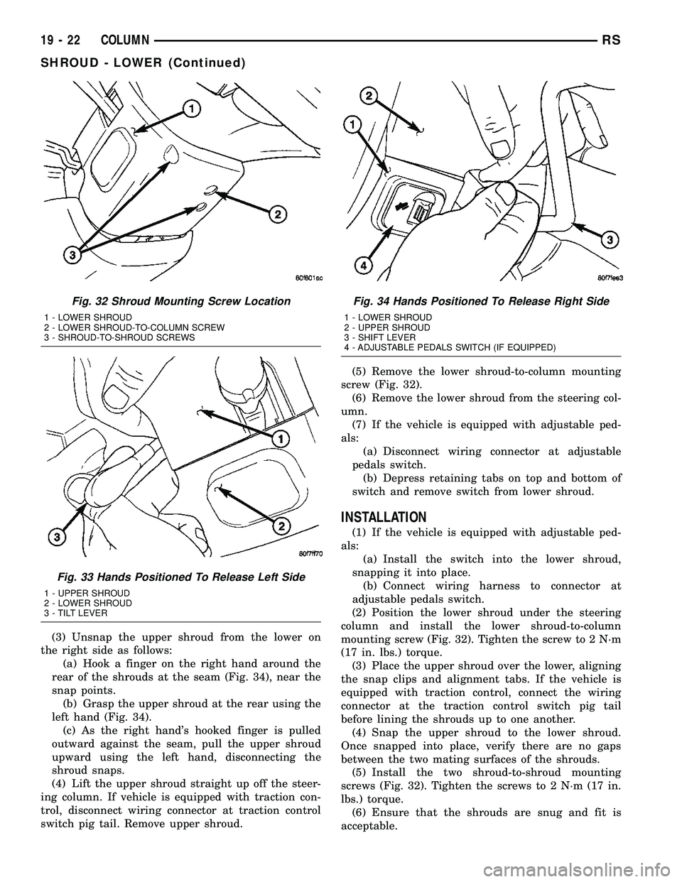
(3) Unsnap the upper shroud from the lower on
the right side as follows:
(a) Hook a finger on the right hand around the
rear of the shrouds at the seam (Fig. 34), near the
snap points.
(b) Grasp the upper shroud at the rear using the
left hand (Fig. 34).
(c) As the right hand's hooked finger is pulled
outward against the seam, pull the upper shroud
upward using the left hand, disconnecting the
shroud snaps.
(4) Lift the upper shroud straight up off the steer-
ing column. If vehicle is equipped with traction con-
trol, disconnect wiring connector at traction control
switch pig tail. Remove upper shroud.(5) Remove the lower shroud-to-column mounting
screw (Fig. 32).
(6) Remove the lower shroud from the steering col-
umn.
(7) If the vehicle is equipped with adjustable ped-
als:
(a) Disconnect wiring connector at adjustable
pedals switch.
(b) Depress retaining tabs on top and bottom of
switch and remove switch from lower shroud.
INSTALLATION
(1) If the vehicle is equipped with adjustable ped-
als:
(a) Install the switch into the lower shroud,
snapping it into place.
(b) Connect wiring harness to connector at
adjustable pedals switch.
(2) Position the lower shroud under the steering
column and install the lower shroud-to-column
mounting screw (Fig. 32). Tighten the screw to 2 N´m
(17 in. lbs.) torque.
(3) Place the upper shroud over the lower, aligning
the snap clips and alignment tabs. If the vehicle is
equipped with traction control, connect the wiring
connector at the traction control switch pig tail
before lining the shrouds up to one another.
(4) Snap the upper shroud to the lower shroud.
Once snapped into place, verify there are no gaps
between the two mating surfaces of the shrouds.
(5) Install the two shroud-to-shroud mounting
screws (Fig. 32). Tighten the screws to 2 N´m (17 in.
lbs.) torque.
(6) Ensure that the shrouds are snug and fit is
acceptable.
Fig. 32 Shroud Mounting Screw Location
1 - LOWER SHROUD
2 - LOWER SHROUD-TO-COLUMN SCREW
3 - SHROUD-TO-SHROUD SCREWS
Fig. 33 Hands Positioned To Release Left Side
1 - UPPER SHROUD
2 - LOWER SHROUD
3 - TILT LEVER
Fig. 34 Hands Positioned To Release Right Side
1 - LOWER SHROUD
2 - UPPER SHROUD
3 - SHIFT LEVER
4 - ADJUSTABLE PEDALS SWITCH (IF EQUIPPED)
19 - 22 COLUMNRS
SHROUD - LOWER (Continued)
Page 1568 of 2585
SHROUD - UPPER
REMOVAL
(1) Remove the two shroud-to-shroud mounting
screws from the lower shroud (Fig. 32).
(2) Unsnap the upper shroud from the lower on
the left side as follows:
(a) Hook a finger on the left hand around the
rear of the shrouds at the seam (Fig. 33), near the
snap points.
(b) Grasp the upper shroud at the rear using the
right hand (Fig. 33).
(c) As the left hand's hooked finger is pulled out-
ward against the seam, pull the upper shroud
upward using the right hand, disconnecting the
shroud snaps.
(3) Unsnap the upper shroud from the lower on
the right side as follows:
(a) Hook a finger on the right hand around the
rear of the shrouds at the seam (Fig. 34), near the
snap points.
(b) Grasp the upper shroud at the rear using the
left hand (Fig. 34).
(c) As the right hand's hooked finger is pulled
outward against the seam, pull the upper shroud
upward using the left hand, disconnecting the
shroud snaps.
(4) Lift the upper shroud straight up off the steer-
ing column. If vehicle is equipped with traction con-
trol, disconnect wiring connector at traction control
switch pig tail. If vehicle is equipped with power fold-
away mirrors (Export), disconnect wiring connector
at mirror switch pig tail. Remove upper shroud.
(5) If vehicle is equipped with traction control,
remove traction control switch from shroud.
(6) If vehicle is equipped with power foldaway mir-
rors (Export), remove power fold-away switch from
upper shroud.
INSTALLATION
(1) If the vehicle is equipped with power foldaway
mirrors (Export), install the power fold-away switch
in the upper shroud.
(2) If vehicle is equipped with traction control,
install the traction control switch in the upper
shroud.
(3) Place the upper shroud over the lower shroud,
aligning the snap clips and alignment tabs. If the
vehicle is equipped with traction control, connect the
wiring connector at the traction control switch pig
tail before lining the shrouds up to one another.
(4) Snap the upper shroud to the lower shroud.
Once snapped into place, verify there are no gaps
between the two mating surfaces of the shrouds.(5) Install the two shroud-to-shroud mounting
screws (Fig. 32). Tighten the screws to 2 N´m (17 in.
lbs.) torque.
(6) Ensure that the shrouds are snug and fit is
acceptable.
STEERING WHEEL
REMOVAL
NOTE: Before proceeding, (Refer to 19 - STEERING/
COLUMN - WARNING)(Refer to 8 - ELECTRICAL/RE-
STRAINTS - WARNING).
(1) Adjust the steering wheel so that the tires are
in thestraight-aheadposition.
(2) Disconnect and isolate the battery negative
cable.
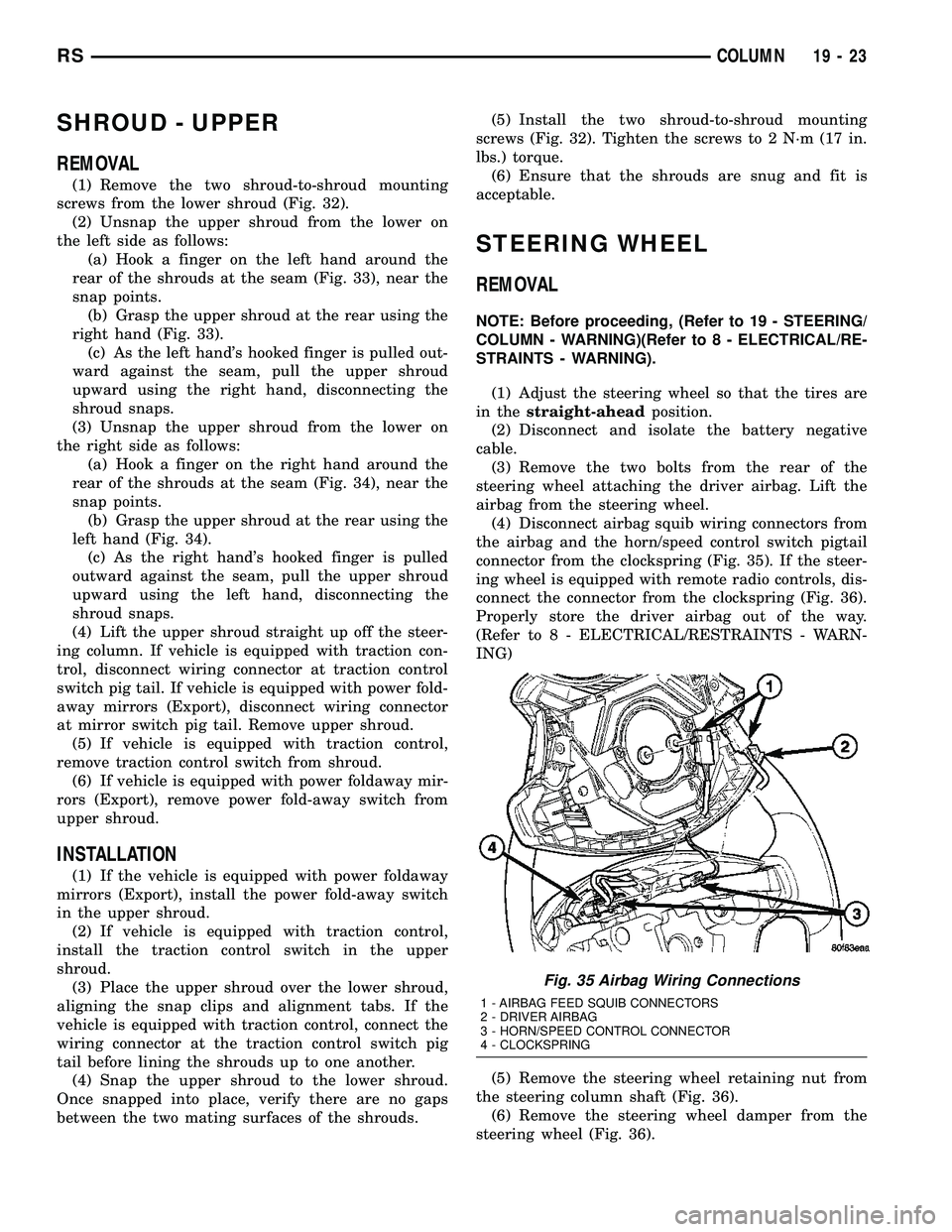
(3) Remove the two bolts from the rear of the
steering wheel attaching the driver airbag. Lift the
airbag from the steering wheel.
(4) Disconnect airbag squib wiring connectors from
the airbag and the horn/speed control switch pigtail
connector from the clockspring (Fig. 35). If the steer-
ing wheel is equipped with remote radio controls, dis-
connect the connector from the clockspring (Fig. 36).
Properly store the driver airbag out of the way.
(Refer to 8 - ELECTRICAL/RESTRAINTS - WARN-
ING)
(5) Remove the steering wheel retaining nut from
the steering column shaft (Fig. 36).
(6) Remove the steering wheel damper from the
steering wheel (Fig. 36).
Fig. 35 Airbag Wiring Connections
1 - AIRBAG FEED SQUIB CONNECTORS
2 - DRIVER AIRBAG
3 - HORN/SPEED CONTROL CONNECTOR
4 - CLOCKSPRING
RSCOLUMN19-23