2004 DODGE TOWN AND COUNTRY flat tire
[x] Cancel search: flat tirePage 548 of 2585
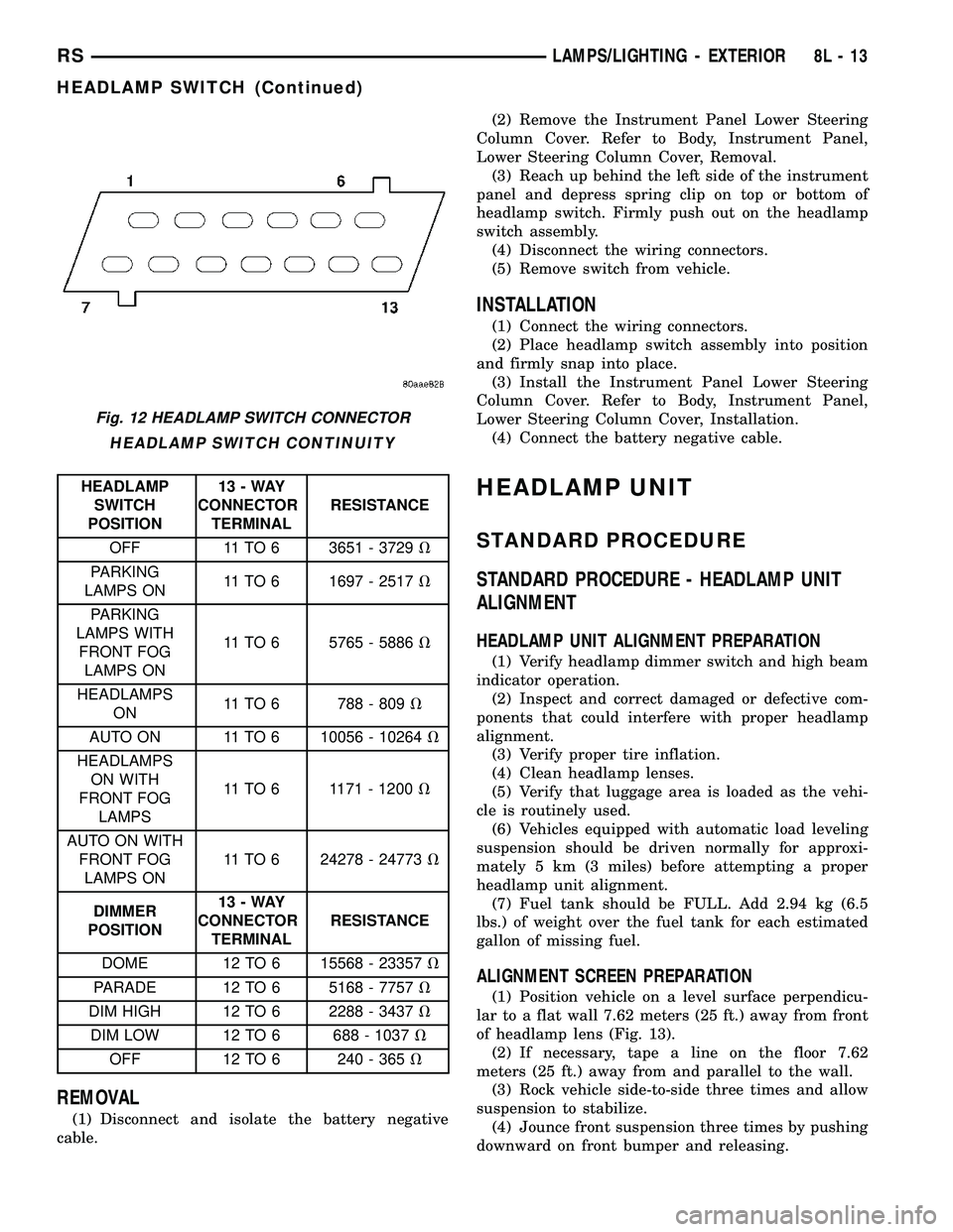
HEADLAMP SWITCH CONTINUITY
HEADLAMP
SWITCH
POSITION13-WAY
CONNECTOR
TERMINALRESISTANCE
OFF 11 TO 6 3651 - 3729V
PARKING
LAMPS ON11 TO 6 1697 - 2517V
PARKING
LAMPS WITH
FRONT FOG
LAMPS ON11 TO 6 5765 - 5886V
HEADLAMPS
ON11 TO 6 788 - 809V
AUTO ON 11 TO 6 10056 - 10264V
HEADLAMPS
ON WITH
FRONT FOG
LAMPS11 TO 6 1171 - 1200V
AUTO ON WITH
FRONT FOG
LAMPS ON11 TO 6 24278 - 24773V
DIMMER
POSITION13-WAY
CONNECTOR
TERMINALRESISTANCE
DOME 12 TO 6 15568 - 23357V
PARADE 12 TO 6 5168 - 7757V
DIM HIGH 12 TO 6 2288 - 3437V
DIM LOW 12 TO 6 688 - 1037V
OFF 12 TO 6 240 - 365V
REMOVAL
(1) Disconnect and isolate the battery negative
cable.(2) Remove the Instrument Panel Lower Steering
Column Cover. Refer to Body, Instrument Panel,
Lower Steering Column Cover, Removal.
(3) Reach up behind the left side of the instrument
panel and depress spring clip on top or bottom of
headlamp switch. Firmly push out on the headlamp
switch assembly.
(4) Disconnect the wiring connectors.
(5) Remove switch from vehicle.
INSTALLATION
(1) Connect the wiring connectors.
(2) Place headlamp switch assembly into position
and firmly snap into place.
(3) Install the Instrument Panel Lower Steering
Column Cover. Refer to Body, Instrument Panel,
Lower Steering Column Cover, Installation.
(4) Connect the battery negative cable.
HEADLAMP UNIT
STANDARD PROCEDURE
STANDARD PROCEDURE - HEADLAMP UNIT
ALIGNMENT
HEADLAMP UNIT ALIGNMENT PREPARATION
(1) Verify headlamp dimmer switch and high beam
indicator operation.
(2) Inspect and correct damaged or defective com-
ponents that could interfere with proper headlamp
alignment.
(3) Verify proper tire inflation.
(4) Clean headlamp lenses.
(5) Verify that luggage area is loaded as the vehi-
cle is routinely used.
(6) Vehicles equipped with automatic load leveling
suspension should be driven normally for approxi-
mately 5 km (3 miles) before attempting a proper
headlamp unit alignment.
(7) Fuel tank should be FULL. Add 2.94 kg (6.5
lbs.) of weight over the fuel tank for each estimated
gallon of missing fuel.
ALIGNMENT SCREEN PREPARATION
(1) Position vehicle on a level surface perpendicu-
lar to a flat wall 7.62 meters (25 ft.) away from front
of headlamp lens (Fig. 13).
(2) If necessary, tape a line on the floor 7.62
meters (25 ft.) away from and parallel to the wall.
(3) Rock vehicle side-to-side three times and allow
suspension to stabilize.
(4) Jounce front suspension three times by pushing
downward on front bumper and releasing.
Fig. 12 HEADLAMP SWITCH CONNECTOR
RSLAMPS/LIGHTING - EXTERIOR8L-13
HEADLAMP SWITCH (Continued)
Page 550 of 2585

(3) Verify proper tire inflation.
(4) Clean headlamp lenses.
(5) Verify that luggage area is loaded as the vehi-
cle is routinely used.
(6) Vehicles equipped with automatic load leveling
suspension should be driven normally for approxi-
mately 5 km (3 miles) before attempting a proper
headlamp unit alignment.
(7) Fuel tank should be FULL. Add 2.94 kg (6.5
lbs.) of weight over the fuel tank for each estimated
gallon of missing fuel.
ALIGNMENT SCREEN PREPARATION
(1) Position vehicle on a level surface perpendicu-
lar to a flat wall 10 meters (32.8 ft.) away from front
of headlamp lens (Fig. 15).
(2) If necessary, tape a line on the floor 10 meters
(32.8 ft.) away from and parallel to the wall.
(3) Rock vehicle side-to-side three times and allow
suspension to stabilize.
(4) Jounce front suspension three times by pushing
downward on front bumper and releasing.
(5) Measure the distance from the center of head-
lamp lens to the floor. Transfer measurement to the
alignment screen (with tape). Use this line for
up/down adjustment reference.
HEADLAMP UNIT ADJUSTMENT
The low beam headlamp will project on the screen
upper edge of the beam (cut-off) at the horizontal
lamp cut-off line 20 mm (0.75 in.). The high beam
pattern should be correct when the low beams are
aligned properly (Fig. 15). To adjust headlamp align-
ment, rotate adjustment screws (Fig. 16) to achieve
the specified low beam cut-off location.
REMOVAL
(1) Disconnect and isolate the battery negative
cable.
(2) Remove the three retaining screws (Fig. 17).
(3) Disconnect the wiring harness from the bulbs
(Fig. 18).
(4) Remove wire harness retainer from back of
headlamp unit.
(5) Remove the headlamp unit.
Fig. 14 HEADLAMP UNIT ADJUSTMENT
1 - ADJUSTMENT LOCATION
2 - HEADLAMP UNIT
RSLAMPS/LIGHTING - EXTERIOR8L-15
HEADLAMP UNIT (Continued)
Page 627 of 2585
OPERATION
The memory switch has three momentary switch
buttons labeled Set, 1 and 2. When the memory set
switch is depressed, a resistance value is sent to the
Body Control Module via hard wired connections.
When the memory system is in ªsetº mode a chime
will be generated by the body control module.
See the owner's manual in the vehicle glove box for
more information on the features, use and operation
of the memory switch.
DIAGNOSIS AND TESTING - MEMORY SWITCH
(1) Remove the memory set switch from the driv-
ers door panel (Refer to 8 - ELECTRICAL/POWER
SEATS/MEMORY SET SWITCH - REMOVAL).
(2) Using an ohmmeter, check the continuity of the
memory select switch MUX circuit between the C2
wire harness connector for the body control module
and the wire harness connector for the memory
switch. There should be continuity. If OK, go to Step
3. If not OK, repair the open or shorted MUX circuit
as required.
(3) Using an ohmmeter, check the continuity of the
memory select switch return circuit between the C2
wire harness connector for the body control module
and the wire harness connector for the memory
switch. There should be continuity. If OK, go to Step
4. If not OK, repair the open or shorted return circuit
as required.
(4) Using an ohmmeter, test the resistances of the
memory switch at the pins in the switch connector
receptacle in each switch position. See the Memory
Switch Test Table. If OK, refer toDiagnosis and
Testing Memory Systemin this section. If not OK,
replace the faulty memory set switch.
MEMORY SWITCH TEST TABLE
MEMORY
SWITCH
POSITIONRESISTANCE
BETWEEN
PINSRESISTANCE
RANGE
(OHMS)
NEUTRAL 1&2 24650 5%
(24.65 k)
MEMORY 1 1&2 6850 5%
(6.85 k)
MEMORY 2 1&2 2100 5%
(2.10 k)
SET 1&2 4490 5%
(4.49 k)
REMOVAL
(1) Disconnect and isolate the battery negative
cable.
(2) Remove the front door trim panel switch bezel
from the driver side front door. Using a thin flat-bladed pry tool, gently pry the switch bezel away
from the drivers door trim panel.
(3) Disconnect the memory switch wire harness
connector from the memory switch.
(4) Remove the two screws that secure the memory
switch to the back of the driver side front door trim
panel switch bezel.
(5) Remove the memory switch.
INSTALLATION
(1) Position the memory switch and install and
tighten the two screws that secure the memory
switch to the back of the driver side front door trim
panel switch bezel. Tighten the screws to 2.2 N´m (20
in. lbs.).
(2) Reconnect the memory switch wire harness
connector to the memory switch.
(3) Install the trim panel switch bezel onto the
driver side front door.
(4) Reconnect the battery negative cable.
PASSENGER SEAT SWITCH
DESCRIPTION
Vehicles equipped with a passenger side power seat
utilize a four-way power seat switch. This four-way
power seat switch features two knobs ganged
together on the outboard seat cushion side shield.
The switch is secured to the back of the seat cush-
ion side shield with two screws. However, the control
knobs for the seat switch unit must be removed
before the seat switch can be removed from the side
shield.
The power seat switch cannot be repaired. If one
switch is damaged or faulty, the entire power seat
switch unit must be replaced.
OPERATION
When a power seat switch control knob or knobs
are actuated, a battery feed and a ground path are
applied through the switch contacts to the power seat
track or recliner adjuster motor. The selected
adjuster motor operates to move the seat track or
recliner through its drive unit in the selected direc-
tion until the switch is released, or until the travel
limit of the adjuster is reached. When the switch is
moved in the opposite direction, the battery feed and
ground path to the motor are reversed through the
switch contacts. This causes the adjuster motor to
run in the opposite direction.
No power seat switch should be held applied in any
direction after the adjuster has reached its travel
limit. The power seat adjuster motors each contain a
self-resetting circuit breaker to protect them from
overload. However, consecutive or frequent resetting
8N - 56 POWER SEAT SYSTEMRS
MEMORY SET SWITCH (Continued)
Page 650 of 2585
OPERATION
The memory switch has three momentary switch
buttons labeled Set, 1 and 2. When the memory set
switch is depressed, a resistance value is sent to the
Body Control Module via hard wired connections.
When the memory system is in ªsetº mode a chime
will be generated by the body control module. See the owner's manual in the vehicle glove box for
more information on the features, use and operation
of the memory switch.
DIAGNOSIS AND TESTING - MEMORY SWITCH
(1) Remove the memory set switch from the driv-
ers door panel (Refer t o 8 - ELECTRICAL/POWER
SEATS/MEMORY SET SWITCH - REMOVAL). (2) Using an ohmmeter, check the continuity of the
memory select switch MUX circuit between the C2
wire harness connector for the body control module
and the wire harness connector for the memory
switch. There should be continuity. If OK, go to Step
3. If not OK, repair the open or shorted MUX circuit
as required. (3) Using an ohmmeter, check the continuity of the
memory select switch return circuit between the C2
wire harness connector for the body control module
and the wire harness connector for the memory
switch. There should be continuity. If OK, go to Step
4. If not OK, repair the open or shorted return circuit
as required. (4) Using an ohmmeter, test the resistances of the
memory switch at the pins in the switch connector
receptacle in each switch position. See the Memory
Switch Test Table. If OK, refer to Diagnosis and
Testing Memory System in this section. If not OK,
replace the faulty memory set switch.
MEMORY SWITCH TEST TABLE
MEMORY SWITCH
POSITION RESISTANCE
BETWEEN PINS RESISTANCE
RANGE
(OHMS)
NEUTRAL 1&2 24650 5% (24.65 k)
MEMORY 1 1&2 6850 5% (6.85 k)
MEMORY 2 1&2 2100 5% (2.10 k)
SET 1&2 4490 5% (4.49 k)
REMOVAL
(1) Disconnect and isolate the battery negative
cable. (2) Remove the front door trim panel switch bezel
from the driver side front door. Using a thin flat-
bladed pry tool, gently pry the switch bezel away
from the drivers door trim panel. (3) Disconnect the memory switch wire harness
connector from the memory switch. (4) Remove the two screws that secure the memory
switch to the back of the driver side front door trim
panel switch bezel. (5) Remove the memory switch.
INSTALLATION
(1) Position the memory switch and install and
tighten the two screws that secure the memory
switch to the back of the driver side front door trim
panel switch bezel. Tighten the screws to 2.2 N´m (20
in. lbs.). (2) Reconnect the memory switch wire harness
connector to the memory switch. (3) Install the trim panel switch bezel onto the
driver side front door. (4) Reconnect the battery negative cable.
PASSENGER SEAT SWITCH
DESCRIPTION
Vehicles equipped with a passenger side power seat
utilize a four-way power seat switch. This four-way
power seat switch features two knobs ganged
together on the outboard seat cushion side shield. The switch is secured to the back of the seat cush-
ion side shield with two screws. However, the control
knobs for the seat switch unit must be removed
before the seat switch can be removed from the side
shield. The power seat switch cannot be repaired. If one
switch is damaged or faulty, the entire power seat
switch unit must be replaced.
OPERATION
When a power seat switch control knob or knobs
are actuated, a battery feed and a ground path are
applied through the switch contacts to the power seat
track or recliner adjuster motor. The selected
adjuster motor operates to move the seat track or
recliner through its drive unit in the selected direc-
tion until the switch is released, or until the travel
limit of the adjuster is reached. When the switch is
moved in the opposite direction, the battery feed and
ground path to the motor are reversed through the
switch contacts. This causes the adjuster motor to
run in the opposite direction.
RS POWER SEAT SYSTEM8Ns-13
MEMORY SET SWITCH (Continued)
Page 662 of 2585
(7) Disconnect the 4±way harness connector from
the speed control/horn harness to the clock spring.
INSTALLATION
DEPLOYED AIRBAG
(1) Perform clean up procedure (Refer to 8 - ELEC-
TRICAL/RESTRAINTS - STANDARD PROCEDURE
- SERVICE AFTER AN AIRBAG DEPLOYMENT).
(2) Install a new steering column assembly and
lower steering column coupler (Refer to 19 - STEER-
ING/COLUMN - INSTALLATION).
(3) Install the new clock spring.
(4) Connect the 4-way and 6-way connectors
between the clock spring and the instrument panel
wiring harness.
(5) Install the steering column shrouds and con-
nect traction control wire connector (if equipped)
(Refer to 19 - STEERING/COLUMN/LOWER
SHROUD - INSTALLATION).
(6) Install the steering wheel (Refer to 19 -
STEERING/COLUMN/STEERING WHEEL -
INSTALLATION).
(7) Connect the 4±way harness connector to the
speed control/horn harness to the clock spring.
(8) Connect the 2±way connector to the remote
radio control harness.
(9) Install the driver airbag and the two screws
retaining the airbag. Tighten screws to 10 N´m (90
in. lbs.)
WARNING: DO NOT CONNECT THE BATTERY NEG-
ATIVE CABLE (Refer to 8 - ELECTRICAL/RE-
STRAINTS - DIAGNOSIS AND TESTING).
PERSONAL INJURY OR DEATH MAY RESULT IF
THE SYSTEM TEST IS NOT PERFORMED PROP-
ERLY.
UNDEPLOYED AIRBAG
(1) Connect the harness connector on the DAB
cover (horn, speed controls) to the clock spring.
(2) Connect the squib connectors to the DAB.
(3) Position a new airbag into the airbag cavity.
(4) Install the two screws retaining the airbag.
Tighten screws to 10 N´m (90 in. lbs.)
WARNING: DO NOT CONNECT THE BATTERY NEG-
ATIVE CABLE (Refer to 8 - ELECTRICAL/RE-
STRAINTS - DIAGNOSIS AND TESTING).
PERSONAL INJURY OR DEATH MAY RESULT IF
THE SYSTEM TEST IS NOT PERFORMED PROP-
ERLY.
DRIVER AIRBAG TRIM COVER
REMOVAL
The horn switch is integral to the driver airbag
trim cover. If either component is faulty or damaged,
the entire driver airbag trim cover and horn switch
unit must be replaced.
(1) Disconnect and isolate the battery negative
cable. Wait two minutes for the system capacitor to
discharge.
(2) Remove the driver airbag from the steering
wheel (Refer to 8 - ELECTRICAL/RESTRAINTS/
DRIVER AIRBAG - REMOVAL).
(3) Remove the plastic wire retainer that captures
the horn switch feed pigtail wire between the upper
left inflator stud and the inflator on the back of the
driver airbag housing and disconnect the speed con-
trol switches (if equipped).
(4) Remove the four nuts that secure the trim
cover retainer to the studs on the back of the driver
airbag housing.
(5) Remove the horn switch ground pigtail wire
eyelet terminal from the upper left airbag housing
stud.
(6) Remove the trim cover retainer from the airbag
housing studs.
(7) Disengage the six trim cover locking blocks
from the lip around the outside edge of the driver
airbag housing and remove the housing from the
cover.
INSTALLATION
(1) Install the housing into the cover. Engage the
six trim cover locking blocks to the lip around the
outside edge of the driver airbag housing.
(2) Install the trim cover retainer to the airbag
housing studs.
(3) Install the horn switch ground pigtail wire eye-
let terminal to the upper left airbag housing stud.
(4) Install the four nuts that secure the upper and
lower trim cover retainers to the studs on the back of
the driver airbag housing. Torque nuts to 6.8 N´m (60
in. lbs.).
(5) Install the plastic wire retainer that captures
the horn switch feed pigtail wire between the upper
left inflator stud and the inflator on the back of the
driver airbag housing.
(6) Connect speed control switches (if equipped).
(7) Install the driver airbag onto the steering
wheel (Refer to 8 - ELECTRICAL/RESTRAINTS/
DRIVER AIRBAG - INSTALLATION).
RSRESTRAINTS8O-7
DRIVER AIRBAG (Continued)
Page 666 of 2585
(13) Install wiring connectors to radio. Install
radio and four retaining screws.
(14) Connect glove box lamp wiring connector and
place right lower instrument panel trim (glove box
surround) into position.
(15) Install nineteen right lower instrument panel
trim (glove box surround) and install panel screws.
(16) Slide cup holder assembly into instrument
panel.
(17) Install center bezel wiring connectors to
HVAC control and switch assembly (hazard, rear
wiper/washer, heated seats).
(18) Install instrument panel center bezel by align-
ing slots and firmly snapping into place.
(19) Install two screws to instrument panel center
bezel.
(20) Align filler bezel above cup holder over retain-
ing slots and firmly snap into place.
(21) Place instrument panel top cover into position
and firmly snap down rear edge of top cover.
(22) Install glove box. Align hinges, snap into
place, roll glove box upwards and push in sides to
fully install.
(23) Align right side upper A-pillar trim over
retaining slots and firmly snap into place.
(24) Align right A-pillar lower extension trim over
retaining slots and firmly snap into place.
(25) Align right instrument panel end cap over
retaining slots and firmly snap into place.
(26) Align right cowl panel over retaining slots and
firmly snap into place.
(27) Align right front door sill plate over retaining
slots and firmly snap into place.
(28) Install two right side nuts at instrument
panel center stack support to floor.
(29) Install two left side nuts at instrument panel
center stack support to floor.
(30) Connect the two wiring connectors to lower
instrument panel cubby bin at bottom of center stack
and install six screws.
(31) Align left side upper A-pillar trim over retain-
ing slots and firmly snap into place.
(32) Install four nuts at brake pedal support
bracket to instrument panel.
(33) Align left A-pillar lower extension trim over
retaining slots and firmly snap into place.
(34) Install knee blocker and retaining screws.
(35) Install Data Link Connector (DLC) into bot-
tom of knee blocker.
(36) Align parking brake lever and snap into place
on knee blocker reinforcement.
(37) Install lower steering column cover and four
retaining screws
(38) Align left cowl panel over retaining slots and
firmly snap into place.(39) Align left front door sill plate over retaining
slots and firmly snap into place.
(40) Install center console bin between front seats.
WARNING: DO NOT CONNECT THE BATTERY NEG-
ATIVE CABLE (Refer to 8 - ELECTRICAL/RE-
STRAINTS - DIAGNOSIS AND TESTING).
PERSONAL INJURY OR DEATH MAY RESULT IF
THE SYSTEM TEST IS NOT PERFORMED PROP-
ERLY.
(41) Close hood.
(42) Verify system and vehicle operation.
SEAT AIRBAG
DESCRIPTION
The side impact airbag system Seat Airbags are
located in the outboard side of the front seat backs.
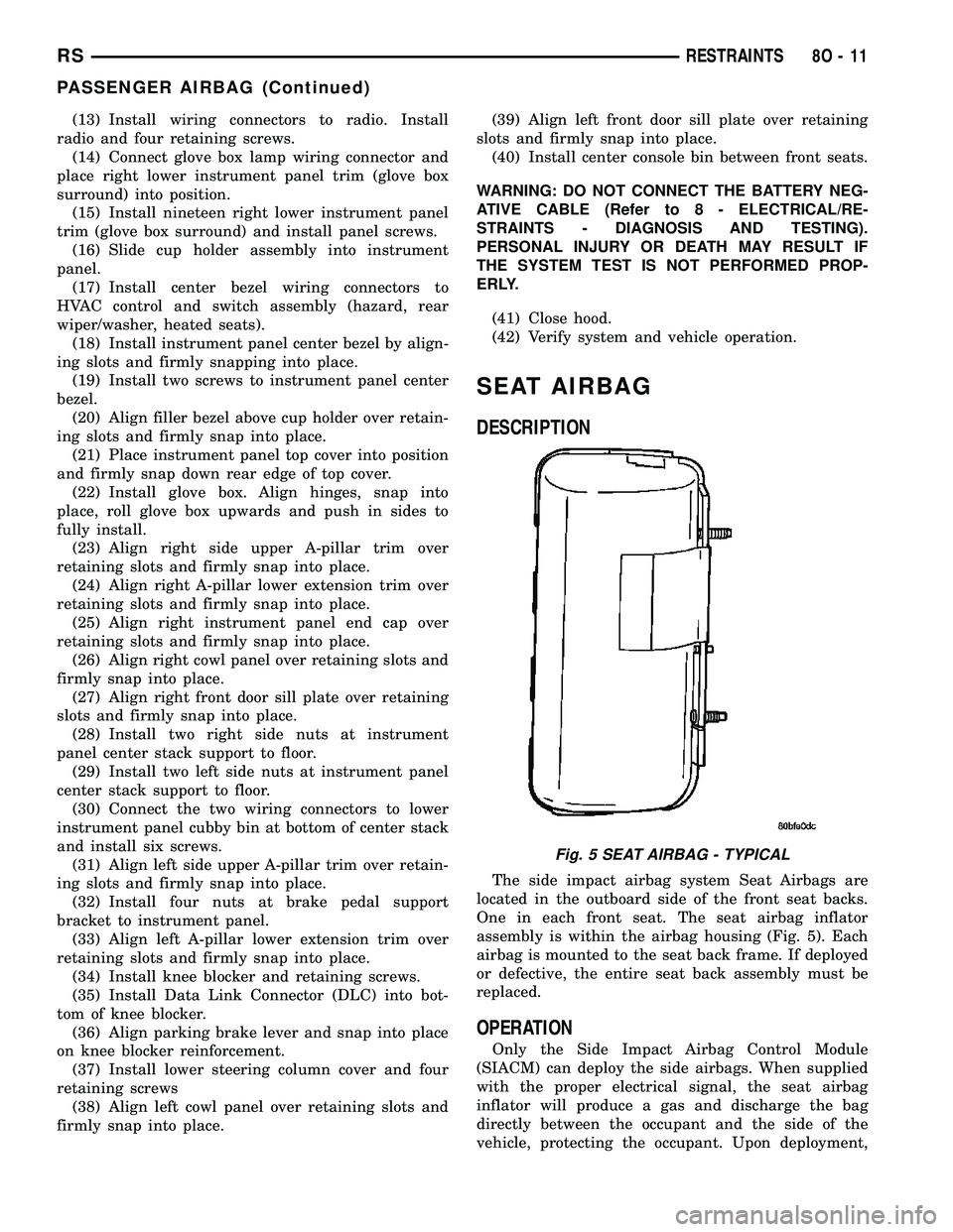
One in each front seat. The seat airbag inflator
assembly is within the airbag housing (Fig. 5). Each
airbag is mounted to the seat back frame. If deployed
or defective, the entire seat back assembly must be
replaced.
OPERATION
Only the Side Impact Airbag Control Module
(SIACM) can deploy the side airbags. When supplied
with the proper electrical signal, the seat airbag
inflator will produce a gas and discharge the bag
directly between the occupant and the side of the
vehicle, protecting the occupant. Upon deployment,
Fig. 5 SEAT AIRBAG - TYPICAL
RSRESTRAINTS8O-11
PASSENGER AIRBAG (Continued)
Page 667 of 2585
the seat back trim cover will tear open and allow the
side airbag to fully inflate and quickly deflate.
SEAT BELT BUCKLE - FRONT
INBOARD
REMOVAL
The seat belt tensioners are integral to the front
seat belt buckles. They are not serviceable and must
be replaced after a frontal impact event. The entire
front seat belt buckle assembly must be replaced as
an assembly.
(1) Disconnect and isolate the battery negative
cable.
(2) Wait two minutes for the system reserve capac-
itor to discharge before beginning any airbag compo-
nent service procedure.
(3) Remove screws attaching front inboard side
cover to seat cushion frame.
(4) Remove side cover from vehicle.
(5) Disconnect the tensioner wire connector from
seat belt buckle.
(6) Remove bolt attaching seat belt buckle to front
seat track.
(7) Remove buckle from vehicle.
INSTALLATION
The seat belt tensioners are integral to the front
seat belt buckles. They are not serviceable and must
be replaced after a frontal impact event. The entire
front seat belt buckle assembly must be replaced as
an assembly.
(1) Place buckle into position.
(2) Install bolt attaching seat belt buckle to front
seat track. Torque bolt to 39 N´m (29 ft. lbs.).
(3) Connect the seat belt tensioner electrical con-
nector.
(4) Install side cover into position.
(5) Install screws attaching front inboard side
cover to seat cushion frame.
WARNING: DO NOT CONNECT THE BATTERY NEG-
ATIVE CABLE (Refer to 8 - ELECTRICAL/RE-
STRAINTS - DIAGNOSIS AND TESTING).
PERSONAL INJURY OR DEATH MAY RESULT IF
THE SYSTEM TEST IS NOT PERFORMED PROP-
ERLY.
SEAT BELT BUCKLE - FIRST
ROW INBOARD - QUAD
BUCKET
REMOVAL
(1) Remove seat from vehicle.
(2) Remove screws attaching inboard side cover to
seat cushion.
(3) Remove side cover from seat.
(4) Remove bolts attaching recliner bracket to seat
cushion.
(5) Remove recliner bracket from seat.
(6) Remove bolt attaching seat belt buckle to seat
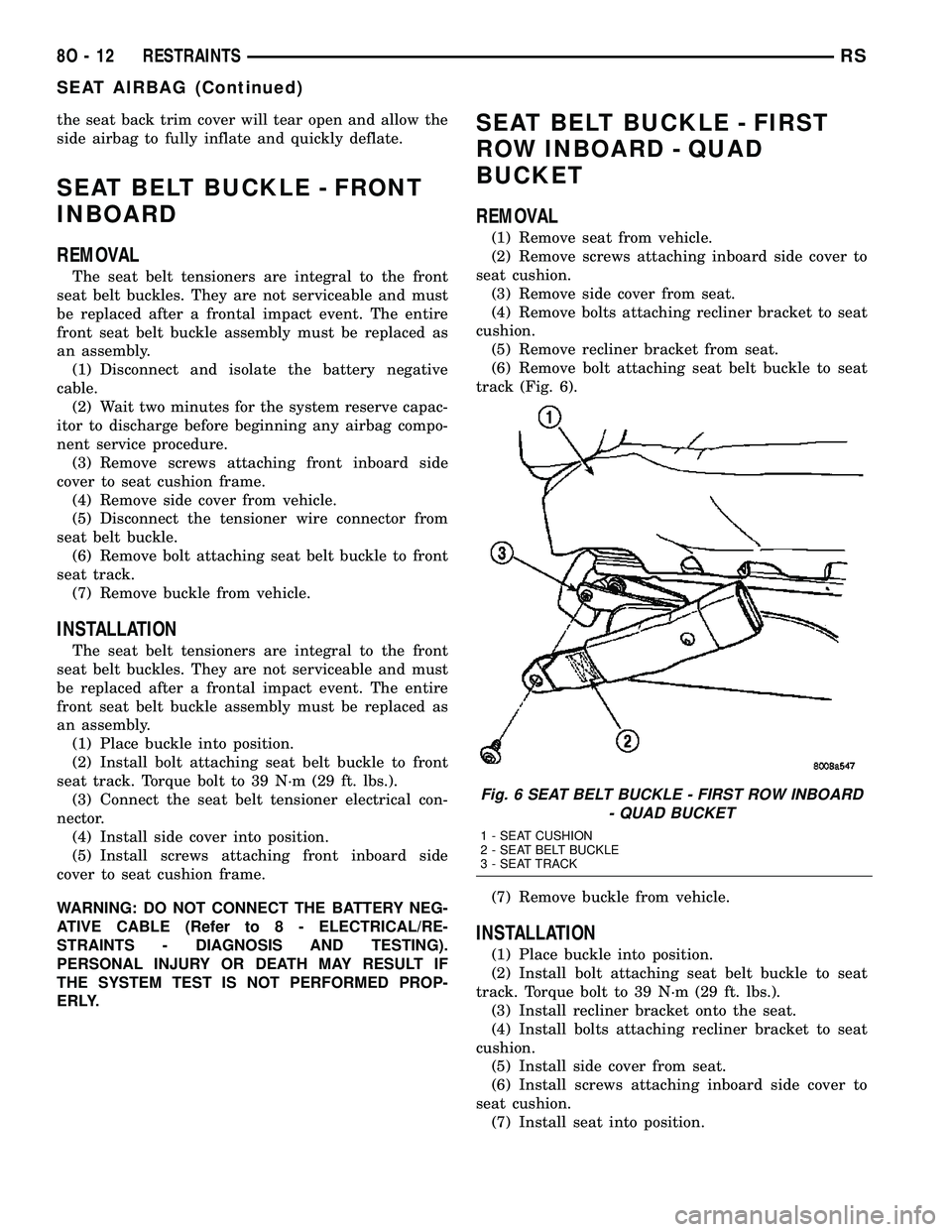
track (Fig. 6).
(7) Remove buckle from vehicle.
INSTALLATION
(1) Place buckle into position.
(2) Install bolt attaching seat belt buckle to seat
track. Torque bolt to 39 N´m (29 ft. lbs.).
(3) Install recliner bracket onto the seat.
(4) Install bolts attaching recliner bracket to seat
cushion.
(5) Install side cover from seat.
(6) Install screws attaching inboard side cover to
seat cushion.
(7) Install seat into position.
Fig. 6 SEAT BELT BUCKLE - FIRST ROW INBOARD
- QUAD BUCKET
1 - SEAT CUSHION
2 - SEAT BELT BUCKLE
3 - SEAT TRACK
8O - 12 RESTRAINTSRS
SEAT AIRBAG (Continued)
Page 682 of 2585
DIAGNOSIS AND TESTING
DIAGNOSIS AND TESTING - SENTRY KEY
REMOTE ENTRY SYSTEM
WARNING: ON VEHICLES EQUIPPED WITH AIR-
BAGS, REFER TO ELECTRICAL, RESTRAINTS,
WARNINGS, BEFORE ATTEMPTING COMPONENT
DIAGNOSIS OR SERVICE. FAILURE TO TAKE THE
PROPER PRECAUTIONS COULD RESULT IN ACCI-
DENTAL AIRBAG DEPLOYMENT AND POSSIBLE
PERSONAL INJURY OR DEATH.
NOTE: The following tests may not prove conclu-
sive in the diagnosis of this system. The most reli-
able, efficient, and accurate means to diagnose the
Sentry Key Remote Entry System (SKREES)
involves the use of a DRBIIITscan tool. Refer to the
proper Body Diagnostic Procedures information.
The Sentry Key Remote Entry System (SKREES)
and the Programmable Communication Interface
(PCI) bus network should be diagnosed using a
DRBIIItscan tool. The DRBIIItwill allow confirma-
tion that the PCI bus is functional, that the Sentry
Key Remote Entry Module (SKREEM) is placing the
proper messages on the PCI bus, and that the Pow-
ertrain Control Module (PCM) is receiving the PCI
bus messages. Refer to the proper Body Diagnostic
Procedures information, and Wiring Diagrams for
complete circuit descriptions and diagrams.
(1) Check the fuses in the Integrated Power Mod-
ule (IPM). If OK, go to Step 2. If not OK, repair the
shorted circuit or component as required and replace
the faulty fuse.
(2) Disconnect and isolate the battery negative
remote cable from the remote terminal. Unplug the
wire harness connector at the SKREEM. Check for
continuity between the ground circuit cavity of the
SKREEM wire harness connector and a good ground.
There should be continuity. If OK, go to Step 3. If not
OK, repair the open circuit to ground as required.
(3) Connect the battery negative cable. Check for
battery voltage at the fused B(+) circuit cavity of the
SKREEM wire harness connector. If OK, go to Step
4. If not OK, repair the open circuit to the fuse in the
IPM as required.
(4) Turn the ignition switch to the ON position.
Check for battery voltage at the fused ignition switch
output (run/start) circuit cavity of the SKREEM wire
harness connector. If OK, use a DRBIIItscan tool
and the proper Body Diagnostic Procedures informa-
tion to complete the diagnosis of the SKREES. If not
OK, repair the open circuit to the fuse in the IPM as
required.
DIAGNOSIS AND TESTING - VEHICLE THEFT
SECURITY SYSTEM
Refer to the appropriate wiring information. The
wiring information includes wiring diagrams, proper
wire and connector repair procedures, further details
on wire harness routing and retention, as well as
pin-out and location views for the various wire har-
ness connectors, splices and grounds. Using a
DRBIIItscan tool. Refer to the proper Body Diagnos-
tic Procedures information for test procedures.
HOOD AJAR SWITCH -
EXPORT
REMOVAL
(1) Disconnect and isolate the battery negative
cable.
(2) Using a small flat blade screwdriver, pry trig-
ger switch from the bracket on the left fender well.
(3) Disconnect the hood ajar switch from the wire
connector and remove from vehicle.
INSTALLATION
(1) Connect the hood ajar switch to the wire conec-
tor.
(2) Press the hood ajar switch into position on the
bracket located on the left inner fender well.
(3) Reconnect the battery negative cable.
(4) Close the hood and check for proper operation.
SENTRY KEY REMOTE ENTRY
MODULE
DESCRIPTION
The Sentry Key Remote Entry Module (SKREEM)
performs the functions of the Sentry Key Immobilizer
Module (SKIM), Remote Keyless Entry (RKE) Mod-
ule, and the Tire Pressure Monitoring (TPM) System
(previously part of the Electronic Vehicle Information
Center (EVIC).
The SKREEM is located in the same location as
the SKIM was and is mounted the same way. It looks
identical, but has added capabilities.
SENTRY KEY IMMOBILIZER
The Sentry Key Immobilizer System (SKIS)
authenticates an electronically coded Transponder
Key placed into the ignition and sends a valid/invalid
key message to the Powertrain Control Module
(PCM) based upon the results. The ªVALID/INVALID
KEYº message communication is performed using a
rolling code algorithm via the Programmable Com-
munication Interface (PCI) data bus. A ªVALID KEYº
RSVEHICLE THEFT SECURITY8Q-3
VEHICLE THEFT SECURITY (Continued)