Page 34 of 273

WARNING!
²Do not put anything on or around the front airbag
covers or attempt to manually open them. You may
damage the airbags and you could be injured be-
cause the airbags are not there to protect you. These
protective covers for the airbag cushions are de-
signed to open only when the airbags are inflating.
²If your vehicle is equipped with left and right
window bags, do not stack luggage or other cargo
up high enough to block the location of the
window bag. The area where the window bag is
located should remain free from any obstructions.
²If your vehicle is equipped with left and right
window bags, do not have any accessory items
installed which will alter the roof, including add-
ing a sunroof to your vehicle. Do not add roof
racks that require permanent attachments (bolts
or screws) for installation on the vehicle roof. Do
not drill into the roof of the vehicle for any reason.
²Do not drill, cut or tamper with the knee bolster in
any way.
²Do not mount any accessories to the knee bolster
such as alarm lights, stereos, citizens band radios
etc.
Airbags inflate in moderate to high speed impacts. Along
with the seat belts, front airbags work with the instru-
ment panel knee bolsters to provide improved protection
for the driver and front passenger. Left and right window
airbags also work with seat belts to improve occupant
protection.
The seat belts are designed to protect you in many types
of collisions. The front airbags deploy only in moderate
to severe frontal collisions. If your vehicle is so equipped,
the window bag on the crash side of the vehicle is
triggered in moderate to severe side collisions. In certain
types of collisions where the airbags deploy, you need the
seat belts to keep you in the right position for the airbags
to protect you properly.
Here are some simple steps you can take to minimize
the risk of harm from a deploying airbag.
1. Children 12 years old and under should ride buckled
up in the rear seat. Infants in rear-facing child restraints
shouldNEVERride in the front seat of a vehicle with a
passenger front airbag. An airbag deployment could
cause severe injury or death to infants in that position.
34 THINGS TO KNOW BEFORE STARTING YOUR VEHICLE
Page 45 of 273

You will first loosen the adjusters on the lower straps and
on the tether strap so that you can more easily attach the
hooks or connectors to the vehicle anchorages. Next
attach the lower hooks or connectors over the top of the
anchorage bars, pushing aside the seat cover material.
Then lift the tether anchorage cover directly behind the
seat where you are placing the child restraint and attach
the tether strap to the anchorage, being careful to route
the tether strap to provide the most direct path between
the anchor and the child restraint. If your vehicle is
equipped with adjustable rear head restraints, raise the
head restraint and, where possible, route the tether strap
under the head restraint and between the two posts. If
not possible, lower the head restraint and route the tether
strap around the outboard side of the head restraint.
Finally, tighten all three straps as you push the child
restraint rearward and downward into the seat, remov-
ing slack in the straps according to the child restraint
manufacturer's instructions.WARNING!
Improper installation of a child restraint to the
LATCH anchorages can lead to failure of an infant or
child restraint. The child could be badly injured or
killed. Follow the manufacturer's directions exactly
when installing an infant or child restraint.
Installing Child Restraints Using the Vehicle Seat
belt
The passenger seat belts are equipped with cinching latch
plates which are designed to keep the lap portion tight
around the child restraint so that it is not necessary to use
a locking clip. Pulling up on the shoulder portion of the
lap/shoulder belt will tighten the belt. The cinching latch
plate will keep the belt tight, however, any seat belt
system will loosen with time, so check the belt occasion-
ally and pull it tight if necessary.
THINGS TO KNOW BEFORE STARTING YOUR VEHICLE 45
2
Page 59 of 273
Folding Rear Seat
To provide additional storage area, the rear seatback can
be folded forward. Pull on the loops shown in the picture
to fold down either or both seatbacks.
When returning the rear seat back to the upright position
be sure the seat back is latched.WARNING!
The cargo area in the rear of the vehicle (with the
rear seatbacks in the locked-up or folded down
position) should not be used as a play area by
children when the vehicle is in motion. They could
be seriously injured in an accident. Children should
be seated and using the proper restraint system.
UNDERSTANDING THE FEATURES OF YOUR VEHICLE 59
3
Page 61 of 273

WARNING!
If the hood is not fully latched it could fly up when
the vehicle is moving and block your forward vision.
You could have a collision. Be sure all hood latches
are fully latched before driving.
LIGHTS
Interior Lights
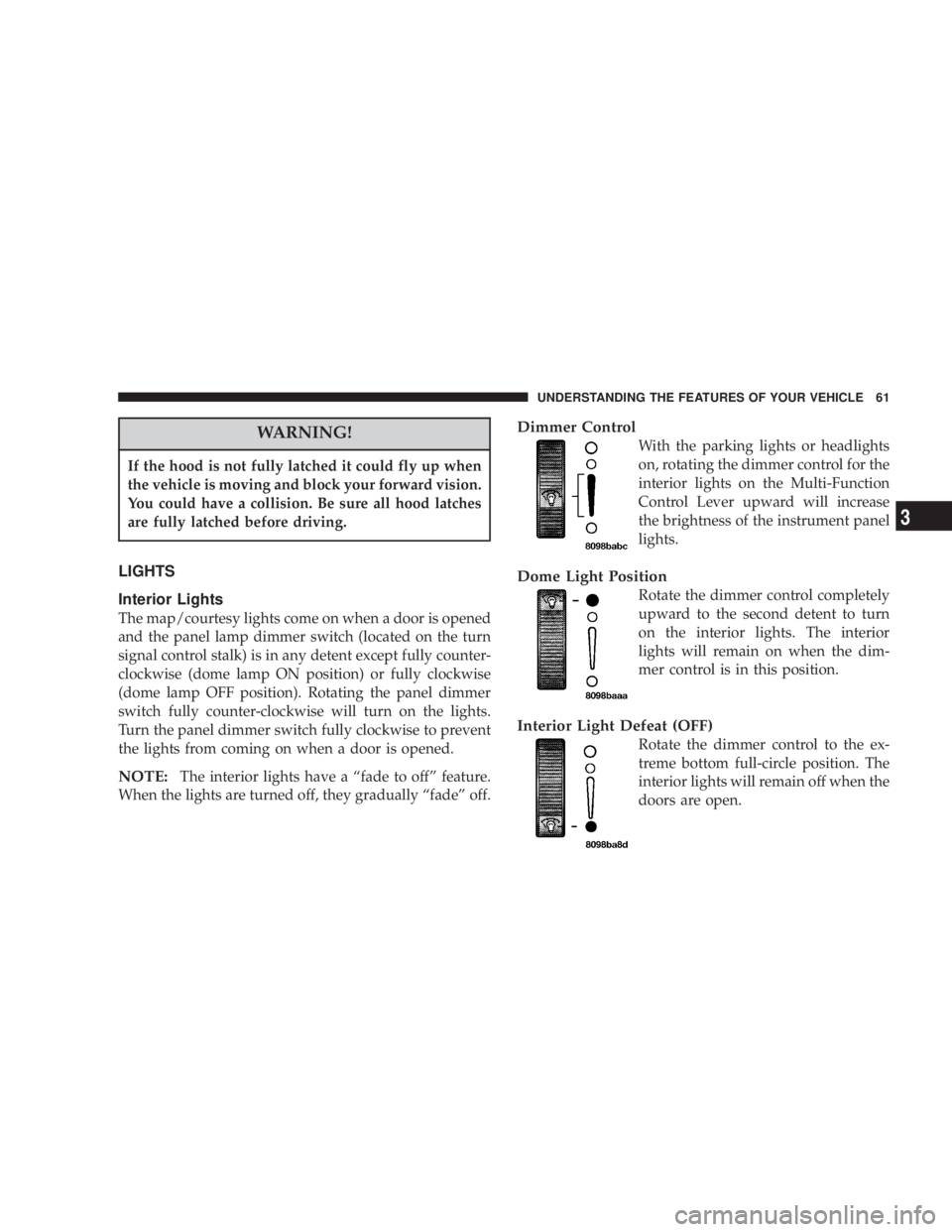
The map/courtesy lights come on when a door is opened
and the panel lamp dimmer switch (located on the turn
signal control stalk) is in any detent except fully counter-
clockwise (dome lamp ON position) or fully clockwise
(dome lamp OFF position). Rotating the panel dimmer
switch fully counter-clockwise will turn on the lights.
Turn the panel dimmer switch fully clockwise to prevent
the lights from coming on when a door is opened.
NOTE:The interior lights have a ªfade to offº feature.
When the lights are turned off, they gradually ªfadeº off.
Dimmer Control
With the parking lights or headlights
on, rotating the dimmer control for the
interior lights on the Multi-Function
Control Lever upward will increase
the brightness of the instrument panel
lights.
Dome Light Position
Rotate the dimmer control completely
upward to the second detent to turn
on the interior lights. The interior
lights will remain on when the dim-
mer control is in this position.
Interior Light Defeat (OFF)
Rotate the dimmer control to the ex-
treme bottom full-circle position. The
interior lights will remain off when the
doors are open.
UNDERSTANDING THE FEATURES OF YOUR VEHICLE 61
3
Page 66 of 273

Speed Sensitive Intermittent Wiper System
Use the intermittent wiper when weather conditions
make a single wiping cycle, with a variable pause be-
tween cycles, desirable. Turn the lever to the delay
position, then select the delay interval. The delay can be
regulated from a maximum of approximately 18 seconds
between cycles, to a cycle every 1/2 second.
NOTE:The wiper delay times depend on vehicle speed.
If the vehicle is moving less than 16 km/h (10 mph),
delay times will be doubled.
TILT STEERING COLUMN
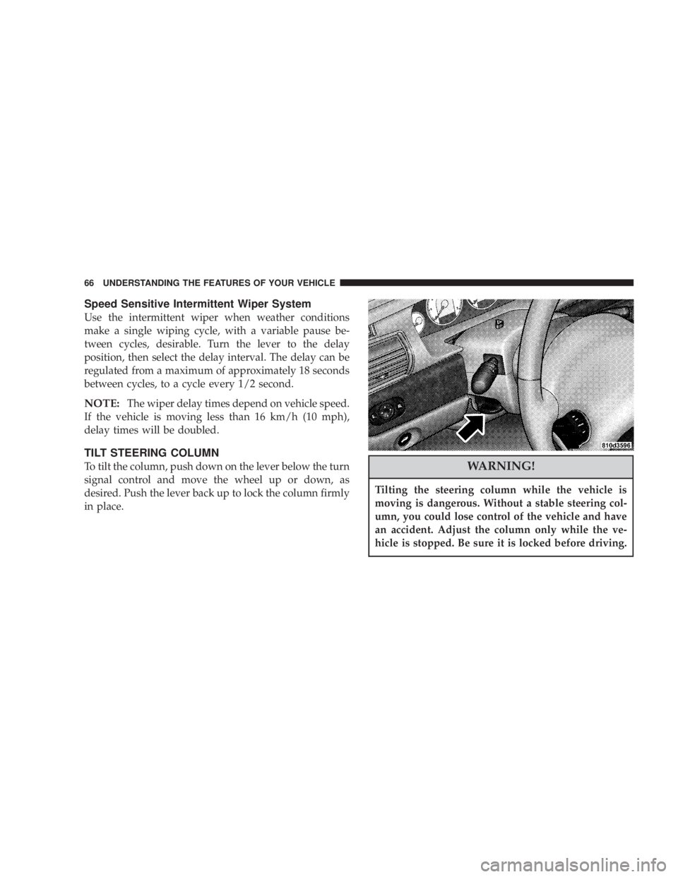
To tilt the column, push down on the lever below the turn
signal control and move the wheel up or down, as
desired. Push the lever back up to lock the column firmly
in place.WARNING!
Tilting the steering column while the vehicle is
moving is dangerous. Without a stable steering col-
umn, you could lose control of the vehicle and have
an accident. Adjust the column only while the ve-
hicle is stopped. Be sure it is locked before driving.
66 UNDERSTANDING THE FEATURES OF YOUR VEHICLE
Page 67 of 273
TRACTION CONTROLÐ IF EQUIPPED
To turn the Traction Control System Off, press
the switch located on the top of the steering
column, to the right of the hazard switch, until
the Traction Control indicator in the instrument
cluster lights up.
To turn the Traction Control System On, press the switch
until the Traction Control indicator in the instrument
cluster turns off.
NOTE:The Traction Control System is enabled each
time the ignition switch is turned On. This will occur
even if you used the switch to turn the system off before
powering down or turning the ignition to Lock.
ELECTRONIC SPEED CONTROLÐ IF EQUIPPED
When engaged, this device will control the throttle op-
eration to maintain a constant vehicle speed between 30
mph (48 km/h) and 85 mph (137 km/h). The controls are
on the steering wheel.
UNDERSTANDING THE FEATURES OF YOUR VEHICLE 67
3
Page 79 of 273

UNDERSTANDING YOUR INSTRUMENT PANEL
CONTENTS
mInstruments And Controls.................83
mInstrument Cluster......................84
mInstrument Cluster Description.............85
mCompass, Temperature, And Trip Computer
Display Ð If Equipped
...................90
NControl Buttons.......................91
NTrip Conditions........................91
NCompass Temperature Display.............92
mCigar Lighter/Ashtray...................94
mElectronic Digital Clock..................94
NTo Set The Clock.......................94
mRadio General Information................94NRadio Broadcast Signals..................94
NTwo Types Of Signals...................95
NElectrical Disturbances...................95
NAM Reception........................95
NFM Reception.........................95
mSales Code RAZÐAM/ FM Stereo Radio With
Cassette Tape Player, CD Player And CD
Changer Controls Ð If Equipped
...........95
NOperating Instructions Ð Radio............95
NPower Switch, Volume Control.............95
NSeek Button (Radio Mode)................96
NTuning..............................96
4
Page 80 of 273

NPTY (Program Type) Button...............96
NBalance.............................97
NFade...............................97
NTone Control.........................97
NAM/FM Selection......................98
NScan Button..........................98
NTo Set The Radio Push-Button Memory.......98
NTo Change From Clock To Radio Mode.......98
NOperating Instructions Ð Tape Player........98
NSeek Button..........................99
NFast Forward (FF)......................99
NRewind (RW).........................99
NTape Eject............................99
NScan Button..........................99
NChanging Tape Direction.................99NMetal Tape Selection....................99
NPinch Roller Release....................99
NNoise Reduction......................100
NOperating Instructions Ð CD Player........100
NInserting The Compact Disc..............100
NSeek Button.........................101
NEJT CD (Eject) Button..................101
NFF/Tune/RW........................101
NProgram Button 4 (Random Play)..........101
NMode..............................102
NTape CD Button......................102
NTime Button.........................102
NScan Button.........................102
NCD Changer Control Capability Ð If
Equipped...........................102
80 UNDERSTANDING YOUR INSTRUMENT PANEL