Page 277 of 388
CAUTION!
Never use extra force with your foot on the wheel
nut wrench or a pipe extension as you can over-
tighten the nut.
12. Lower and remove the jack, and store the jack, flat
tire and chock. Have the damaged tire repaired as soon as
possible.
13. Check tire inflation pressure. Tire inflation pressure
specifications are shown on a placard located on the
driver 's side ``B''-Pillar.
N24A1420
EMERGENCIES 277
8
Page 278 of 388

CAUTION!
²The emergency tire is to be used only temporarily
when the standard tire is damaged. Repair the
damaged tire as soon as possible. Replace the
emergency tire with the standard tire.
²After changing the tire and driving the vehicle
approximately 621 miles (1000 km), retighten the
wheel nuts to make sure that they are not loose.
²If the steering wheel vibrates after changing the
tire, have the tire checked for balance at an autho-
rized dealer.
²Avoid mixing one type of tire with another type or
using tires of a size other than the specified size.
Premature mechanical wear and reduced handling
may result.
ENGINE OVERHEATING
If the engine coolant temperature gauge indicator enters
the ªHº (hot) position, the engine may be overheated.
In any of the following situations, you can reduce the
potential for overheating by taking the appropriate ac-
tion.
²On the highways Ð Slow down.
²In city traffic Ð While stopped, put transaxle in
neutral, but do not increase engine idle speed.
NOTE:There are steps that you can take to slow down
an impending overheat condition. If your air conditioner
is on, turn it off. The air conditioning system adds heat to
the engine cooling system and turning off the A/C
removes this heat. You can also turn the Temperature
control to maximum heat, the Mode control to floor, and
the fan control to High. This allows the heater core to act
as a supplement to the radiator and aids in removing heat
from the engine cooling system.
278 EMERGENCIES
Page 284 of 388

WARNING!
²Always wear protective clothing and goggles
when working near the battery.
²Keep the battery out of the reach of children.
If your vehicle has anti-lock brakes
If the vehicle is driven without sufficient battery charge,
after the engine has been started by using booster cables,
the engine may misfire. This can cause the anti-lock
braking system warning light to blink on and off. This is
a result of insufficient battery voltage; it is not a malfunc-
tion of the brake system. If this happens, fully charge the
battery before driving.
TOWING
When towing your vehicle, all state and local regulations for
towing must be followed. Incorrect towing equipment could
damage your vehicle. When towing is required, contact a
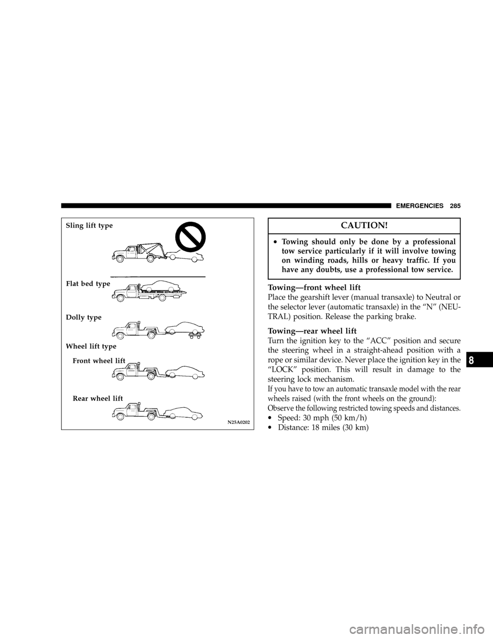
professional towing service and make sure that flat bed type,
dolly type or wheel lift type towing equipment is used. Do
not attempt to be towed by another vehicle with a rope using
the tie-down hooks.
CAUTION!
²Tie-down hooks should never be used for towing
purposes.
²This vehicle can NOT be towed by a tow truck
using sling lift type equipment. This is to prevent
the bumper from deformation. If this vehicle is
towed, use wheel lift, dolly type or flat bed
equipment.
²Use the flat bed type, dolly type or dolly type
equipment if a vehicle has the following condi-
tions:
·Any of the transaxle, axles, steering system or
power train is damaged.
·Automatic transaxle fluid level is low.
284 EMERGENCIES
Page 285 of 388

CAUTION!
²Towing should only be done by a professional
tow service particularly if it will involve towing
on winding roads, hills or heavy traffic. If you
have any doubts, use a professional tow service.
TowingÐfront wheel lift
Place the gearshift lever (manual transaxle) to Neutral or
the selector lever (automatic transaxle) in the ªNº (NEU-
TRAL) position. Release the parking brake.
TowingÐrear wheel lift
Turn the ignition key to the ªACCº position and secure
the steering wheel in a straight-ahead position with a
rope or similar device. Never place the ignition key in the
ªLOCKº position. This will result in damage to the
steering lock mechanism.
If you have to tow an automatic transaxle model with the rear
wheels raised (with the front wheels on the ground):
Observe the following restricted towing speeds and distances.
·Speed: 30 mph (50 km/h)
·Distance: 18 miles (30 km)N25A0202
Sling lift type
Flat bed type
Dolly type
Wheel lift type
Front wheel lift
Rear wheel lift
EMERGENCIES 285
8
Page 286 of 388
CAUTION!
Never tow an automatic transaxle model with the
rear wheels raised (with the front wheels on the
ground) when the automatic transaxle fluid level is
low. This may cause serious and expensive damage
to the transaxle.
FUSESFuse block
To prevent damage to the electrical system due to short-
circuiting or overloading, each individual circuit is pro-
vided with a fuse. There are fuse blocks in the passenger
compartment and in the engine compartment.
The fuse block in the passenger compartment is located on
the driver's side at the position shown in the illustration.
In the engine compartment, the fuse block is located as
shown in the illustration.N09A1230
Passenger compartment
N09A1880
286 EMERGENCIES
Page 310 of 388

NDisconnection and connection.............325
mAutomatic transaxle.....................327
NTo check the fluid level..................328
NProcedure for checking the fluid level.......328
mManual transaxle.......................329
mDisc brake pads, rear drum brake linings
and rear wheel cylinders.................329
mBrake hoses...........................329
mBall joint, steering linkage seal and drive
shaft boots...........................329
mSupplemental Restraint System (SRS)........329
mDoor hinges, rear hatch hinges, hood lock
release mechanism and safety catch
.........330
mExhaust system........................330
mWindshield wiper blades.................331
NWindshield washers....................331
mParking brake.........................332
mDrive belt (for generator, water pump, power
steering pump)
........................333
mTiming belt...........................334
mTi re s................................334
NTire inflation pressures..................334
NRadial ply tires.......................336
N
Tire pressure for sustained high-speed driving...336
NOversize tires........................336
NTire maintenance......................337
NCargo loads..........................337
NTread wear indicators...................337
NTire rotation.........................338
NTire chains...........................339
NSnow tires...........................339
mRegular Maintenance Schedule.............340
mSevere Maintenance Schedule..............349
310 MAINTENANCE
Page 329 of 388

Special additives
DaimlerChrysler does not recommend the addition of
any fluid additives to the transaxle.
MANUAL TRANSAXLE
Add oil to maintain the proper level. Refill or change oil
according to the scheduled maintenance table.
Lubricant Gear Oil Classification GL-4
Viscosity range SAE75W-90 or 75W-85W
DISC BRAKE PADS, REAR DRUM BRAKE
LININGS AND REAR WHEEL CYLINDERS
Proper brakes are essential to safe operation of your
vehicle. Check brake pads and rear brake linings for
wear, and check rear wheel cylinders for leakage.
For proper braking performance, replace brake pads with
original equipment type pads.
BRAKE HOSES
Brake hoses and tubing should be checked for:
1. Severe surface cracking, scuffing or worn spots. If the
casing of the hose is exposed by cracks or abrasions in therubber hose cover, the hose should be replaced. Deterio-
ration of the hose could cause brake failure.
2. Faulty installation may cause twisting, or wheel, tire
or chassis interference.
BALL JOINT, STEERING LINKAGE SEAL AND
DRIVE SHAFT BOOTS
Check the following parts for damage and grease leak-
age:
1. Ball joint boots of the front suspension and steering
linkage
2. Bellows on both ends of the drive shaft
SUPPLEMENTAL RESTRAINT SYSTEM (SRS)
The entire SRS system must be inspected by an autho-
rized dealer 10 years after the vehicle manufacture date
shown on the certification label. [See ªSRS servicingº on
page 100.]
MAINTENANCE 329
9
Page 337 of 388

Tire maintenance
The following maintenance steps are recommended:
1. Check pressure regularly.
2. Maintain wheel balance and front suspension align-
ment.
3. Rotate tires regularly in accordance with the recom-
mendation in the section ªTire rotationº on page 336.
Cargo loads
The load-carrying capacity of your vehicle is shown on
the tire and loading information placard.
DO NOT USE the weight rating data provided on the
safety certification label for determining vehicle passen-
ger and/or cargo load capacity.
For determining the combined weight of occupants and
cargo, use the specifications provided on the tire and
loading information placard.
Tread wear indicators
Tread wear indicators are built into the original equip-
ment tires on your vehicle to assist you in determining
when your tires have been worn to the point of needing
replacement. Many states have laws making tire replace-
ment mandatory at this point.
These indicators are molded into the bottom of the tread
grooves and will appear as 1/2 in (13 mm) wide bands
when tire tread depth becomes 1/16 in (1.6 mm).
M32A0010
Location of tread wear indicator
Tread wear indicator
MAINTENANCE 337
9