Page 215 of 426

²automatic transmission is in Park (P)
²vehicle speed is zero
²Applying the throttle will cancel fast idle
²If the engine is equipped with an aftermarket exhaust
brake (manual transmissions only), operating the ex-
haust brake at idle will greatly improve warm up rate
and will help keep the engine close to operating
temperature during extended idle.
Stopping The Engine
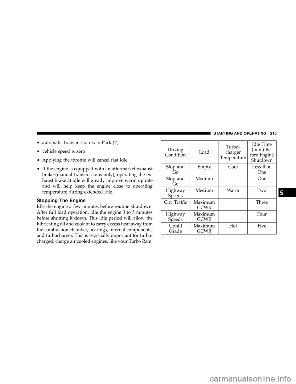
Idle the engine a few minutes before routine shutdown.
After full load operation, idle the engine 3 to 5 minutes
before shutting it down. This idle period will allow the
lubricating oil and coolant to carry excess heat away from
the combustion chamber, bearings, internal components,
and turbocharger. This is especially important for turbo-
charged, charge air cooled engines, like your Turbo Ram.
Driving
ConditionLoadTurbo-
charger
TemperatureIdle Time
(min.) Be-
fore Engine
Shutdown
Stop and
GoEmpty Cool Less than
One
Stop and
GoMedium One
Highway
SpeedsMedium Warm Two
City Traffic Maximum
GCWRThree
Highway
SpeedsMaximum
GCWRFour
Uphill
GradeMaximum
GCWRHot Five
STARTING AND OPERATING 215
5
Page 216 of 426

Engine Speed Control
CAUTION!
Prevent overspeeding the engine going down hill.
When descending steep grades, use a combination of
gears and service brakes to control vehicle/engine
speed. Overspeed can cause severe engine damage.
Operating Precautions
Avoid Overheating The Engine
The temperature of the coolant (a mixture of 50%
ethylene-glycol and 50% water) must not exceed the
normal range of the temperature gauge (240ÉF/116ÉC)
with a 16 psi (110 kPa) radiator cap.
Usually the coolant temperature indicated during opera-
tion will be to the left of center in the normal range of the
gauge.
Avoid Low Coolant Temperature Operation
Continual operation at low coolant temperature below
the normal range on the gauge (140ÉF/60ÉC) can be
harmful to the engine. Low coolant temperature can
cause incomplete combustion which allows carbon and
varnish to form on piston rings and injector nozzles.
Also, the unburned fuel can enter the crankcase, diluting
the lubricating oil and causing rapid wear to the engine.
Cooling System Tips Ð Automatic Transmission
To reduce potential for engine and transmission over-
heating in high ambient temperature conditions, take the
following actions:
²City Driving Ð
when stopped, put transmission in neutral and increase
engine idle speed.
NOTE:The engine speed will automatically increase to
1000 RPM at elevated coolant temperature to improve
engine cooling.
216 STARTING AND OPERATING
Page 217 of 426
²Highway Driving Ð
reduce your speed.
²Up Steep Hills Ð
select a lower transmission gear, but try and keep the
torque converter locked.
²Air Conditioning Ð
turn it off temporarily.
Do Not Operate The Engine With Low Oil
Pressure
When the engine is at normal operating temperature, the
minimum oil pressures required are:
Idle 700 to 800 RPM............... 10psi(69kPa)
Full speed and load.............. 30psi(207 kPa)
CAUTION!
If oil pressure falls to less than normal readings, shut
the engine off immediately. Failure to do so could
result in immediate and severe engine damage.
Do Not Operate The Engine With Failed Parts
Practically all failures give some warning before the parts
fail. Be on the alert for changes in performance, sounds,
and visual evidence that the engine requires service.
Some important clues are:
²engine misfiring or vibrating severely
²sudden loss of power
²unusual engine noises
²fuel, oil or coolant leaks
STARTING AND OPERATING 217
5
Page 218 of 426

²sudden change, outside the normal operating range, in
the engine operating temperature
²excessive smoke
²oil pressure drop
TRANSMISSION SHIFTING
Four-Speed Overdrive Automatic Transmission Ð
If Equipped
The gear shift selector display, located in the instrument
panel cluster, indicates the transmission gear range (the
selector is illuminated for night driving). The selector
lever is mounted on the right side of the steering column.
You must depress the brake pedal, to pull the selector
lever out of park (P) position (Brake Interlock System). To
drive, move the selector lever from Park or Neutral to the
desired drive position. Pull the selector lever toward you
when shifting into Reverse, Second, First or Park, or
when shifting out of Park.
Gear Ranges
DO NOT race the engine when shifting from Park or
Neutral position into another gear range.
ªPº Park
This gear position supplements the parking brake by
locking the transmission. The engine can be started in
this range. Never use Park while the vehicle is in motion.
Apply the parking brake when leaving the vehicle in this
range. Always apply parking brake first, then place the
selector in Park position. On 4-wheel drive vehicles be
sure that the transfer case is in a drive position!
WARNING!
Your vehicle could move and injure you and others if
it is not completely in P (Park). Check by trying to
move the gearshift lever back and forth without first
pulling it toward you after you have set it in P. Make
sure it is in Park before leaving the vehicle.
218 STARTING AND OPERATING
Page 264 of 426

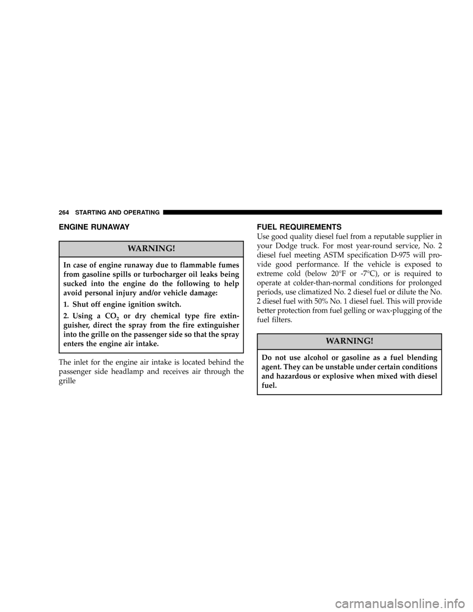
ENGINE RUNAWAY
WARNING!
In case of engine runaway due to flammable fumes
from gasoline spills or turbocharger oil leaks being
sucked into the engine do the following to help
avoid personal injury and/or vehicle damage:
1. Shut off engine ignition switch.
2. Using a CO
2or dry chemical type fire extin-
guisher, direct the spray from the fire extinguisher
into the grille on the passenger side so that the spray
enters the engine air intake.
The inlet for the engine air intake is located behind the
passenger side headlamp and receives air through the
grille
FUEL REQUIREMENTS
Use good quality diesel fuel from a reputable supplier in
your Dodge truck. For most year-round service, No. 2
diesel fuel meeting ASTM specification D-975 will pro-
vide good performance. If the vehicle is exposed to
extreme cold (below 20ÉF or -7ÉC), or is required to
operate at colder-than-normal conditions for prolonged
periods, use climatized No. 2 diesel fuel or dilute the No.
2 diesel fuel with 50% No. 1 diesel fuel. This will provide
better protection from fuel gelling or wax-plugging of the
fuel filters.
WARNING!
Do not use alcohol or gasoline as a fuel blending
agent. They can be unstable under certain conditions
and hazardous or explosive when mixed with diesel
fuel.
264 STARTING AND OPERATING
Page 281 of 426

²Highway DrivingÐreduce your speed.
²Air ConditioningÐturn it off temporarily.
²Hilly TerrainÐTurn overdrive off.
See Cooling System Operating information in the Service
and Maintenance section of this manual for more infor-
mation.
Automatic Transmission Oil Temperature Warning
Light
All vehicles with heavy duty transmission oil cooling are
equipped with a transmission sump oil temperature
sensor and warning light. If elevated transmission tem-
peratures are encountered, the engine controller will
select the most desirable gear until the transmission
temperatures are reduced. If transmission oil tempera-
tures continue to rise, a warning light located in theinstrument cluster will illuminate. If this should occur,
stop the vehicle, shift to Neutral, and run the engine at
idle or faster until the light goes off.
Towing With An Automatic Transmission
Vehicles equipped with an automatic transmission may
shift into and out of Overdrive, or a lower gear, when
driving in hilly areas, when heavily loaded, or when
towing into heavy winds.
When this condition occurs, press the ªTOW/HAULº
button or shift into a lower gear to prevent excessive
transmission wear and/or overheating, and to provide
better engine braking.
NOTE:Do not exceed the following RPM while manu-
ally downshifting:
²5.9L Diesel Engines 3200 RPM.
STARTING AND OPERATING 281
5
Page 306 of 426

hand, it may be necessary to use the jack drive tube in
order to lower the jack. Stow the replaced tire, jack, and
tools as previously described.
9. Adjust the tire pressure when possible.
NOTE:Do not oil wheel studs. For chrome wheels, do
not substitute with chrome plated wheel nuts.
Hub Caps
The hub caps must be removed before raising the vehicle
off the ground.
For 2500/3500 single rear wheel (SRW) models, use the
blade on the end of the lug wrench to pry the cap off.
On 3500 models with dual rear wheels (DRW), you must
first remove the hub caps. The jack handle driver has a
hook at one end that will fit in the pry off notch of the
rear hub caps. Position the hook and pull out on the
ratchet firmly. The cap should pop off. The wheel skins
can now be removed. For the front hub cap on 3500models use the blade on the end of the lug wrench to pry
the caps off. The wheel skin can now be removed.
You must use the flat end of the lug wrench to pry off the
wheel skins. Insert the flat tip completely and using a
back and forth motion, loosen the wheel skin. Repeat this
procedure around the tire until the skin pops off.
Replace the wheel skins first using a rubber mallet. When
replacing the hub caps, tilt the cap retainer over the
lugnut bolt circle and strike the high side down with a
rubber mallet. Be sure that the hub caps and wheel skins
are firmly seated around the wheel.
8-Stud Ð Dual Rear Wheels
Dual wheels are flat mounted, center piloted. The lug
nuts are a two piece assembly. When the tires are being
rotated or replaced, clean these lug nuts and add 2 drops
of oil at the interface between the hex and the washer.
306 WHAT TO DO IN EMERGENCIES
Page 317 of 426
MAINTAINING YOUR VEHICLE
CONTENTS
mEngine Compartment....................320
N5.9L/5.9L HO Cummins Turbo Diesel.......320
mOnboard Diagnostic System (OBD II).........321
mReplacement Parts......................322
mDealer Service.........................322
mService Information.....................322
mMaintenance Procedures..................325
NEngine Oil..........................325
NDrive Belt...........................331NEngine Air Cleaner Filter................331
NDraining Fuel/Water Separator Filter.......334
NMaintenance Free Batteries...............336
NAir Conditioner Maintenance.............338
NPower Steering Ð Fluid Check............339
NFront Suspension Ball Joints..............340
NSteering Linkage Ð Inspection............340
NFront Axle Universal Drive Joints And Pivot
Bearings............................340
7