Page 116 of 397

NOTE: Tire pressure menu items are available only on
vehicles equipped with the Tire Pressure Monitor Sys-
tem.
Customer Programmable Features Ð If Equipped
Press the ªMENUº button until one of the display choices
following appears:
Language
When in this display you may select one of five lan-
guages for all display nomenclature, including the trip
computer functions. Press the ªSTEPº button while in
this display selects English, Francaise, Deutsch, Italiano,
or Espanol. As you continue the displayed information
will be shown in the selected language.
US or Metric
Pressing the ªSTEPº button when in this display selects
US or Metric. The overhead console and climate control
displays will be in the selected units. Service Interval
When this feature is selected a service interval between
2,000 miles (3 200 km) and 6,000 miles (9 600 km) in 500
mile (800 km) increments may be selected. Pressing the
ªSTEPº button when in this display will select distances
between 2,000 miles (3 200 km) and 6,000 miles (9 600
km) in 500 mile (800 km) increments.
Reset Service Distance (Displays Only if Service
Interval was Changed)
When this feature is selected the current accumulated
service distance can be reset to the newly selected service
interval. Pressing the ªSTEPº button when in this display
will select ªYesº or ªNo.º
Retrain Tire Sensors (Available with Tire Pressure
Monitor System Only)
The Tire Pressure Monitor system must be retrained
following a tire rotation or wheel rim mounted sensor
replacement. If you unintentionally choose ªYesº to train116 UNDERSTANDING THE FEATURES OF YOUR VEHICLE
Page 161 of 397
AM Reception
AM sound is based on wave amplitude, so AM reception
can be disrupted by such things as lightning, power lines
and neon signs.
FM Reception
Because FM transmission is based on frequency varia-
tions, interference that consists of amplitude variations
can be filtered out, leaving the reception relatively clear,
which is the major feature of FM radio.
NOTE: On vehicles so equipped the radio, steering
wheel radio controls and 6 disc CD/DVD changer if
equipped, will remain active for up to 45 seconds after
the ignition switch has been turned off. Opening a
vehicle front door will cancel this feature. SALES CODE RAZÐAM/ FM STEREO RADIO
WITH CASSETTE TAPE PLAYER, CD PLAYER
AND CD CHANGER CONTROLS Ð IF EQUIPPED
Operating Instructions Ð Radio
NOTE: Power to operate the radio is controlled by the
ignition switch. It must be in the ON or ACC position to
operate the radio. UNDERSTANDING YOUR INSTRUMENT PANEL 161
4
Page 195 of 397

NOTE: Follow the manufactures instructions for the
correct colors when connecting the RCA cables.
Operating Instructions Ð Video
Games/Camcorders
A video game unit or camcorder can be connected to the
rear audio/video system. Connect the cables to the RCA
jacks located on the front of the CD/DVD changer.
NOTE: To operate a video game unit a DC to AC
adapter may be required, plug the adapter into any
power outlet.
Follow the manufactures instructions for the correct
colors when connecting the RCA cables.
NOTE: MP3 player's, video game systems, camcorders
connected to the RCA jacks and CD's or DVD's inserted
into the CD/DVD changer can be heard through the
headphones. REMOTE SOUND SYSTEM CONTROLS Ð IF
EQUIPPED
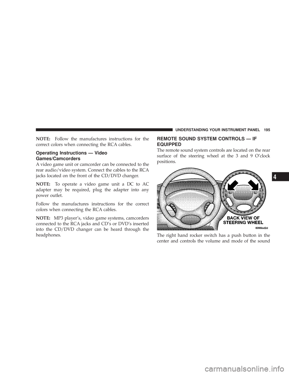
The remote sound system controls are located on the rear
surface of the steering wheel at the 3 and 9 O'clock
positions.
The right hand rocker switch has a push button in the
center and controls the volume and mode of the sound UNDERSTANDING YOUR INSTRUMENT PANEL 195
4
Page 258 of 397

WARNING!² Do not use a tire, wheel size or rating other than that
specified for your vehicle. Some combinations of
unapproved tires and wheels may change suspen-
sion dimensions and performance characteristics,
resulting in changes to steering, handling, and brak-
ing of your vehicle. This can cause unpredictable
handling and stress to steering and suspension com-
ponents. You could lose control and have an accident
resulting in serious injury or death. Use only the tire
and wheel sizes with load ratings approved for your
vehicle.
² Never use a tire with a smaller load index or capacity,
other than what was originally equipped on your
vehicle. Using a tire with a smaller load index could
result in tire overloading and failure. You could lose
control and have an accident.
² Failure to equip your vehicle with tires having
adequate speed capability can result in sudden tire
failure and loss of vehicle control. CAUTION!Replacing original tires with tires of a different size
may result in false speedometer and odometer read-
ings.
Alignment And Balance
Poor suspension alignment may result in:
² fast tire wear;
² uneven tire wear, such as feathering and one-sided
wear;
² vehicle pull to right or left.
Tires may also cause the vehicle to pull to the left or right.
Alignment will not correct this condition. See your dealer
for proper diagnosis.258 STARTING AND OPERATING
Page 284 of 397
Spare Tire Removal
Fit the jack-handle over the drive nut. Rotate the nut to
the left until the spare is on the ground with enough slack
cable to allow you to pull the tire out from under the
vehicle.
CAUTION!The winch mechanism is designed for use with the
jack handle only. Use of an air wrench or other
power tools is not recommended and can damage the
winch.
When the spare is clear, tilt the retainer at the end of the
cable and pull it through the center of the wheel. Preparations For Jacking
Park the vehicle on a firm level surface, avoid ice or
slippery areas, set the parking brake and place the gear
selector in PARK. Turn OFF the ignition.
WARNING!Do not attempt to change a tire on the side of the
vehicle close to moving traffic. Pull far enough off
the road to avoid the danger of being hit when
operating the jack or changing the wheel.
² Turn on the Hazard Warning Flasher.284 WHAT TO DO IN EMERGENCIES
Page 285 of 397
² Block both the front and rear
of the wheel diagonally oppo-
site the jacking position. For
example, if changing the right
front tire, block the left rear
wheel.
² Passengers should not remain in the vehicle when the
vehicle is being jacked.
Jacking Instructions
1. Remove the spare wheel, scissors jack and jack-handle
from stowage.
2. Loosen (but do not remove) the wheel lug nuts by
turning them to the left one turn while the wheel is still
on the ground.
3. There are two jack engagement locations on each side
of the body Ð see illustration. 4. These locations are on the sill flange of the body and
consist of a pair of downstanding tabs. The jack is to be
located, engaging the flange, between the pair of tabs
closest to the wheel to be changed. Place the wrench on
the jack screw and turn to the right until the jack head is WHAT TO DO IN EMERGENCIES 285
6
Page 329 of 397

NOTE: Refer to Section 8 of this manual for Mainte-
nance Schedules.
If the transmission is disassembled for any reason, the
fluid and filter should be changed.
Special Additives
Do not add any fluid additives to the transmission. The
only exception to this policy is the use of special dyes to
aid in detecting fluid leaks. The use of transmission
sealers should be avoided as they may adversely affect
seals. All Wheel Drive (AWD)
Under normal operating conditions, periodic fluid level
checks and lubricant changes for the Power Transfer
Unit, Overrunning Clutch and Rear Carrier, are not
required. However when the vehicle is serviced for other
reasons, the exterior surface of these components should
be inspected for evidence of fluid leaks. Confirmed leaks
should be repaired as soon as possible.
Power Transfer Unit
The fluid should be maintained at the bottom of the filler
hole opening. If it becomes necessary to add or replace
the fluid, use only the manufacturers recommended
fluid, refer to Recommended Fluids, Lubricants and
Genuine Parts for correct fluid type.
Overrunning Clutch
The fluid should be maintained at the bottom of the filler
hole opening. If it becomes necessary to add or replace
the fluid, use only the manufacturers recommended MAINTAINING YOUR VEHICLE 329
7
Page 330 of 397

transmission fluid, refer to Recommended Fluids, Lubri-
cants and Genuine Parts for correct fluid type. To assure
performance, it is important that the proper lubricant be
used.
Rear Carrier
The fluid should be maintained at the bottom of the filler
hole opening. if it becomes necessary to add or replace
the fluid, use only the manufacturers recommended
fluid, refer to Recommended Fluids, Lubricants and
Genuine Parts for correct fluid type.
Fluid Changes
The fluid should be changed as follows:
Normal Usage No Service Required
Severe Usage
Power Transfer Unit 15,000 miles (24 000 km)
Overrunning Clutch 22,500 miles (36 000 km)
Rear Carrier 22,500 miles (36 000 km) Severe Usage is defined as:
1. More than 50% of vehicle operation in stop and go
traffic where the vehicle is driven regularly for more than
45 minutes of continuous operation, such as in heavy city
or in construction zone traffic,
2. Police, taxi, limousine, commercial type operation, or
trailer towing where the vehicle is driven regularly for
more than 45 minutes of continuous operation.
Front And Rear Wheel Bearings
Front and rear wheel bearings are permanently sealed.
No regular maintenance is required for these compo-
nents.
Appearance Care and Protection from Corrosion
Protection of Body and Paint from Corrosion
Vehicle body care requirements vary according to geo-
graphic locations and usage. Chemicals that make roads
passable in snow and ice, and those that are sprayed on330 MAINTAINING YOUR VEHICLE