Page 245 of 397

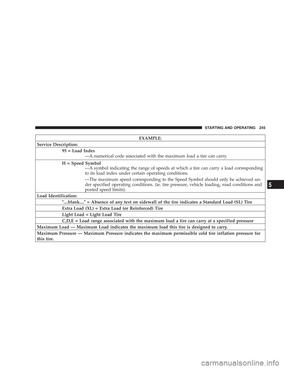
EXAMPLE:
Service Description:
95 = Load Index
ÐA numerical code associated with the maximum load a tire can carry.
H = Speed Symbol
ÐA symbol indicating the range of speeds at which a tire can carry a load corresponding
to its load index under certain operating conditions.
ÐThe maximum speed corresponding to the Speed Symbol should only be achieved un-
der specified operating conditions. (ie. tire pressure, vehicle loading, road conditions and
posted speed limits).
Load Identification:
( ....blank.... ( = Absence of any text on sidewall of the tire indicates a Standard Load (SL) Tire
Extra Load (XL) = Extra Load (or Reinforced) Tire
Light Load = Light Load Tire
C,D,E = Load range associated with the maximum load a tire can carry at a specified pressure
Maximum Load Ð Maximum Load indicates the maximum load this tire is designed to carry.
Maximum Pressure Ð Maximum Pressure indicates the maximum permissible cold tire inflation pressure for
this tire. STARTING AND OPERATING 245
5
Page 285 of 397
² Block both the front and rear
of the wheel diagonally oppo-
site the jacking position. For
example, if changing the right
front tire, block the left rear
wheel.
² Passengers should not remain in the vehicle when the
vehicle is being jacked.
Jacking Instructions
1. Remove the spare wheel, scissors jack and jack-handle
from stowage.
2. Loosen (but do not remove) the wheel lug nuts by
turning them to the left one turn while the wheel is still
on the ground.
3. There are two jack engagement locations on each side
of the body Ð see illustration. 4. These locations are on the sill flange of the body and
consist of a pair of downstanding tabs. The jack is to be
located, engaging the flange, between the pair of tabs
closest to the wheel to be changed. Place the wrench on
the jack screw and turn to the right until the jack head is WHAT TO DO IN EMERGENCIES 285
6
Page 296 of 397

N Front Suspension Ball Joints ..............314
N Steering Shaft Seal ....................314
N Steering Linkage ......................315
N Drive Shaft Universal Joints ..............315
N Body Lubrication .....................315
N Windshield Wiper Blades ................316
N Windshield And Rear Window Washers .....316
N Exhaust System ......................317
N Cooling System .......................318
N Hoses And Vacuum/Vapor Harnesses .......322
N Brakes .............................323
N Master Cylinder Ð ABS Brakes Brake Fluid
Level Check .........................324 N Fuel System Hoses ....................326
N Automatic Transmission ................326
N All Wheel Drive (AWD) .................329
N Front And Rear Wheel Bearings ...........330
N Appearance Care And Protection From
Corrosion ...........................330
N Cleaning The Instrument Panel And
Underseat Cup Holders .................334
m Integrated Power Module (IPM) ............336
m Vehicle Storage ........................337
m Replacement Light Bulbs .................338
m Bulb Replacement ......................339
N Headlights ..........................339296 MAINTAINING YOUR VEHICLE
Page 324 of 397

Insure nylon tubing in these areas has not melted or
collapsed.
Inspect all hose connections such as clamps and cou-
plings to make sure they are secure and no leaks are
present.
NOTE: Often, fluid such as oil, power steering fluid,
and brake fluid are used during assembly plant opera-
tions to facilitate the assembly of hoses to couplings.
Therefore, oil wetness at the hose-coupling area is not
necessarily an indication of leakage. Actual dripping of
hot fluid when systems are under pressure (during
vehicle operation), should be noted before hose is re-
placed based on leakage.
NOTE: Inspection of brake hoses should be performed
whenever the brake system is serviced and every engine
oil change. Inspect hydraulic brake hoses for surface
cracking, scuffing, or worn spots. If there is any evidence
of cracking, scuffing, or worn spots, the hose should be replaced immediately! Eventual deterioration of the hose
can take place resulting in a possibility of a burst failure.
WARNING!Worn brake hoses can burst and cause brake failure.
You could have an accident. If you see any signs of
cracking, scuffing, or worn spots, have the brake
hoses replaced immediately.
Master Cylinder Ð ABS Brakes Brake Fluid Level
Check
The fluid level in the master cylinder should be checked
when performing underhood services, or immediately if
the brake system warning light indicates system failure.
Clean the top of the master cylinder area before removing
the cap. Add fluid to bring the level up to the top of the
ªFULLº mark on the side of the master cylinder reservoir.324 MAINTAINING YOUR VEHICLE
Page 342 of 397
Rear Tail, Stop, Turn Signal, Side Marker and
Back-up Lights
1. Raise the liftgate.
2. Remove the two light assembly push-in type fasteners.
3. Squeeze the socket assembly tabs to remove it from the
housing. 4. Pull the bulb to remove it from the socket.
5. Replace the bulb, reinstall the socket, and reattach the
light assembly.342 MAINTAINING YOUR VEHICLE
Page 375 of 397
Contract, and you require service after your manufactur-
er's new vehicle limited warranty expires, please refer to
your contract documents, and contact the person listed in
those documents.
We appreciate that you have made a major investment
when you purchased your new vehicle. Your dealer has
also made a major investment in facilities, tools, and
training to assure that you are absolutely delighted with
your ownership experience. You'll be pleased with their
sincere efforts to resolve any warranty issues or related
concerns.
WARRANTY INFORMATION
See your manufacturer's Warranty Information Booklet
for information on warranty coverage and transfer of
warranty. MOPAR T PARTS
Mopar t fluids, lubricants, parts, and accessories are
available from your dealer. They will help you keep your
vehicle operating at its best. IF YOU NEED CONSUMER ASSISTANCE 375
9