Page 1562 of 2643

ZF 4 HP 16 AUTOMATIC TRANSAXLE 5A1 – 213
DAEWOO V–121 BL4
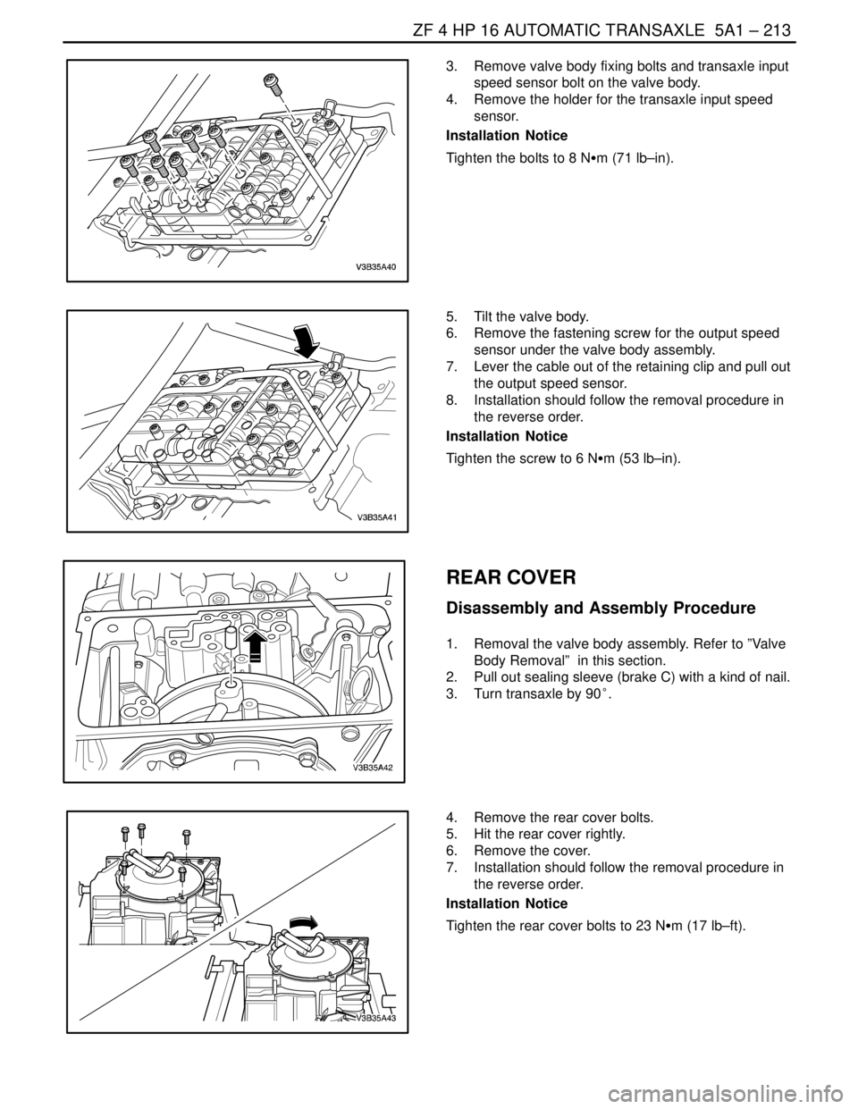
3. Remove valve body fixing bolts and transaxle input
speed sensor bolt on the valve body.
4. Remove the holder for the transaxle input speed
sensor.
Installation Notice
Tighten the bolts to 8 NSm (71 lb–in).
5. Tilt the valve body.
6. Remove the fastening screw for the output speed
sensor under the valve body assembly.
7. Lever the cable out of the retaining clip and pull out
the output speed sensor.
8. Installation should follow the removal procedure in
the reverse order.
Installation Notice
Tighten the screw to 6 NSm (53 lb–in).
REAR COVER
Disassembly and Assembly Procedure
1. Removal the valve body assembly. Refer to ”Valve
Body Removal” in this section.
2. Pull out sealing sleeve (brake C) with a kind of nail.
3. Turn transaxle by 90°.
4. Remove the rear cover bolts.
5. Hit the rear cover rightly.
6. Remove the cover.
7. Installation should follow the removal procedure in
the reverse order.
Installation Notice
Tighten the rear cover bolts to 23 NSm (17 lb–ft).
Page 1581 of 2643

5A1 – 232IZF 4 HP 16 AUTOMATIC TRANSAXLE
DAEWOO V–121 BL4
GENERAL DESCRIPTION
AND SYSTEM OPERATION
The ZF 4HP 16 automatic transaxle consists primarily of
the following components.
Mechanical
S Torque converter with TCC
S Drive link assembly
S Two multiple disk clutch assemblies : Clutch B,E
S Three multiple brake assemblies : Brake C,D,F
S Lock–up clutch valve
S Two planetary gear sets
S One oil pump
S Final drive and differential assembly
Electronic
S Two shift solenoid valve(sol.1,2)
S Four pressure control solenoid valve(EDS)
S Two speed sensors : A/T ISS and A/T OSS
S Fluid temperature sensor
S Automatic transaxle control module(TCM)
S Wiring harness assembly
MECHANICAL COMPONENTS
Torque Converter
The converter consists of the impeller, the turbine wheel,
the reaction member (stator) and the oil to transmit torque.
The impeller, which is driven by the engine, causes the oil
in the converter to flow in a circular pattern. This oil flow
meets the turbine wheel, where is direction of flow is de-
flected. At the hub, the oil leaves the turbine and reaches
the reaction member (stator), where it is once again de-
flected so that it reaches the impeller at the correct angle
of flow.
The reversal effect generates movement in the stator, the
reaction torque then amplifies the turbine torque.
The ratio between turbine torque and torque is referred to
as torque multiplication.
The greater the difference is speed between the pump and
turbine, the greater the torque multiplication; it is at its
highest when the turbine is at a standstill. The higher the
speed of the turbine, the lower the torque multiplication.
When the turbine speed reaches about 85%of the pump
speed, torque multiplication=1, i.e. the turbine torque
equivalent to pump torque.
The stator, which bears against the housing via the free-
wheel, is then rotating freely in the oil flow and the free-
wheel is over–come. From this point onwards, the con-
verter acts as a straightforward fluid coupling.
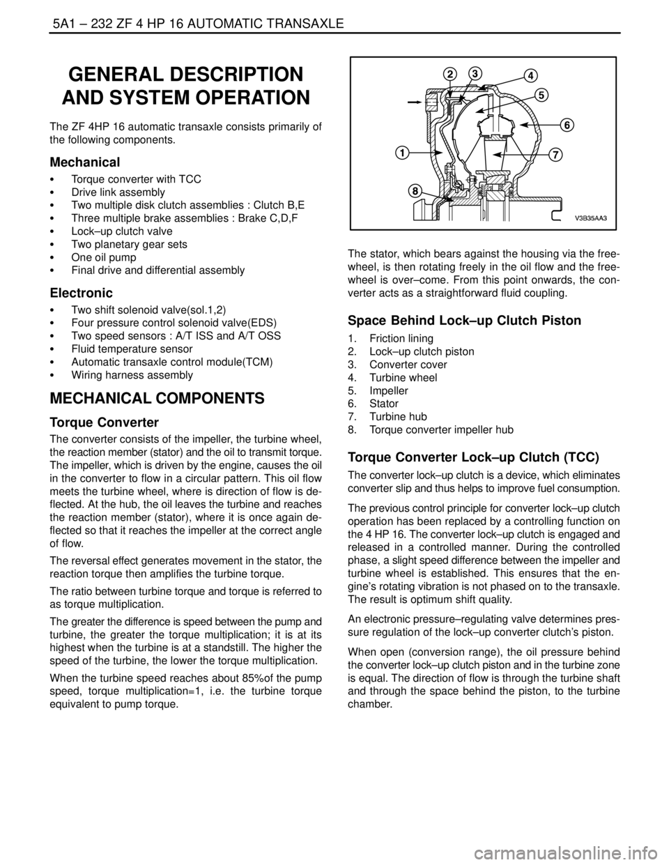
Space Behind Lock–up Clutch Piston
1. Friction lining
2. Lock–up clutch piston
3. Converter cover
4. Turbine wheel
5. Impeller
6. Stator
7. Turbine hub
8. Torque converter impeller hub
Torque Converter Lock–up Clutch (TCC)
The converter lock–up clutch is a device, which eliminates
converter slip and thus helps to improve fuel consumption.
The previous control principle for converter lock–up clutch
operation has been replaced by a controlling function on
the 4 HP 16. The converter lock–up clutch is engaged and
released in a controlled manner. During the controlled
phase, a slight speed difference between the impeller and
turbine wheel is established. This ensures that the en-
gine’s rotating vibration is not phased on to the transaxle.
The result is optimum shift quality.
An electronic pressure–regulating valve determines pres-
sure regulation of the lock–up converter clutch’s piston.
When open (conversion range), the oil pressure behind
the converter lock–up clutch piston and in the turbine zone
is equal. The direction of flow is through the turbine shaft
and through the space behind the piston, to the turbine
chamber.
Page 1590 of 2643

ZF 4 HP 16 AUTOMATIC TRANSAXLE 5A1 – 241
DAEWOO V–121 BL4
TCM INPUTS THAT AFFECT THE 4HP
16 TRANSAXLE
Throttle Position Sensor
S Provides throttle position data to the TCM for deter-
mining shift patterns and TCC apply/release.
S An incorrect throttle position sensor input could
causes erratic or shift pattern, poor shift quality or
TCC function
Automatic Transaxle Output (Shaft) Speed
Sensor
S Provides vehicle speed data to the TCM for deter-
mining shift patterns and TCC apply/release, and
gear ratio calculations.
S An incorrect throttle position sensor input could
causes erratic or shift pattern, poor shift quality or
TCC function
Automatic Transaxle Input (Shaft) Speed
Sensor
S Provides transaxle input speed data to the TCM for
determining shift patterns and TCC apply/release,
and gear ratio.
Engine Coolant Temperature Sensor
S Provides coolant temperature data to the TCM for
determining initial TCC engagement.
S An incorrect engine coolant temperature sensor
input could causes an incorrect initial TCC apply
Engine Speed
S The ignition module provides engine speed data the
TCM.
S The TCM uses engine speed information for con-
trolling wide open throttle shifts and the TCC PWM
solenoid duty cycle.
Stoplamp Switch
S Provides brake apply information to the TCM for
controlling TCC apply and release.
S An incorrect TCC stoplamp switch input could
causes an incorrect TCC apply or release.
Transaxle Fluid Temperature (TFT) Sensor
S Provides transaxle fluid temperature information to
the TCM for determining alternate shift patterns and
TCC apply during high temperature conditions (hot
mode operation).
S An incorrect transaxle temperature sensor input
could causes altered shift patterns, poor shift quali-
ty and incorrect TCC apply.
Page 2220 of 2643
9A – 14IBODY WIRING SYSTEM
DAEWOO V–121 BL4
I/P Fuse Block
FuseRating/SourceCircuit
F110AIGN 1SDM
F210AIGN 1TCM, ECM, Generator, VGIS, VSS
F315AIGN 1Hazard Switch
F410AIGN 1Cluster, DRL Module, Chime Bell, Brake Switch,
SSPS Module, A/C Control Switch
F5–Spare–
F610AIGN 2A/C Comp. Relay, Defog Relay, Power Window
Relay, Head Lamp Relay
F720AIGN 2Blower Relay, A/C Control Switch, FATC
F815AIGN 2Electric Mirror Switch, Folding Mirror, Sun Roof
Module
F925AIGN 1Wiper Motor, Wiper Switch
F10–Spare–
F1110AIGN 1EBCM, Oil Feeding Connector
F1210AIGN 1Immobilizer, Anti Theft Control Unit, Rain Sensor
Unit
F1310AB+TCM
F1415AB+Hazard Switch
F1515AB+Anti Theft Control Unit
F1610AB+DLC
F1710AACCAudio, Clock
F1815AACCExtra Power Jack
F1915AACCCigar Lighter
F2010AIGN 1Reverse Lamp Switch, PNP Switch
F2115AB+Rear Fog Relay
F2215AB+Clock, FATC, A/C Control Switch
F2315AB+Audio
F2410AB+Immobilizer