2004 DAEWOO NUBIRA wheel bolts
[x] Cancel search: wheel boltsPage 1133 of 2643

4F – 52IANTILOCK BRAKE SYSTEM
DAEWOO V–121 BL4
StepNo Yes Value(s) Action
9Check the continuity of the wiring in both front wheel
speed sensor circuits between the ABS connector
and the wheel speed sensor wheel speed sensor
connector on each side of the vehicle.
1. The left side uses terminals 6 and 7 at the ABS
connector.
2. The right side uses terminals 4 and 5 at the
ABS connector.
Is continuity good for both harnesses?–Go to Step 11Go to Step 10
10Repair the discontinuity found in the front wheel
speed sensor harness.
Is the repair complete?–System OK–
111. Visually inspect the wiring for the rear wheel
speed sensors.
2. Check that the wheel speed sensors are prop-
erly mounted and that the retaining bolts are
properly tightened.
Is there any damage?–Go to Step 12Go to Step 13
12Repair or replace components as required.
Is the repair complete?–System OK–
13Remove each wheel speed sensor from the rear
knuckles and inspect the toothed ring through the
wheel speed sensor mounting holes.
1. Check for any damaged or missing teeth.
2. Check that the ring is properly positioned under
the wheel speed sensor.
Is there any damage or other fault with either speed
ring?–Go to Step 14Go to Step 15
14Replace the rear wheel hub with the proper unit.
Is the repair complete?–System OK–
151. Disconnect the rear wheel speed sensor har-
nesses from the wheel speed sensor connec-
tors.
2. Measure the wheel speed sensor resistance at
the wheel speed sensor connector terminals.
Does the resistance fall within the specified values
for both wheel speed sensors?1280–1920 WGo to Step 17Go to Step 16
16Replace the faulty wheel speed sensor.
Is the repair complete?–System OK–
171. The ABS control module connector should still
be disconnected. Disconnect it now if it is not.
2. Check each wheel speed sensor harness for a
short circuit between its wires with a digital
ohmmeter attached to the two terminals at the
harness side of the wheel speed sensor con-
nector.
3. Also check each wheel speed sensor harness
wire for a short to ground from the connector
terminals.
Is there any short circuit in either wheel speed sen-
sor harness?–Go to Step 18Go to Step 19
Page 1354 of 2643

ZF 4 HP 16 AUTOMATIC TRANSAXLE 5A1 – 5
DAEWOO V–121 BL4
SPECIFICATIONS
GENERAL SPECIFICATIONS
Definition
Transaxle Type4–speed with four–wheel drive and transverse engine
Input Torque240 NSm (177 lb–ft)
Transaxle Weight76kg (168 lb)
Torque Converter Capacity9.72kg (21.4 lb)
Transaxle Fluid Type (manufacture company)ESSO LT 71141 or TOTAL ATF H50235
Transaxle Fluid Capacity7.3qt (6.9L)
TRANSAXLE GEAR RATIO
GearRatio
First2.719
Second1.487
Third1.000
Fourth0.717
Reverse 2.529
Final3.945:1
FLUID CAPACITY
LitresQuarts
Bottom Pan Removal44.2
Complete Overhaul6.97.3
Torque Converter Removal22.1
(Measurements are approximate)
FASTENER TIGHTENING SPECIFICATIONS
ApplicationNSmLb–FtLb–In
Bearing Plate Bolts23.517.5–
Slotted Nut220162–
Rear Cover Attachment Bolts23.517.5–
Baffle Plate Attachment Bolts10–89
Park/Neutral Position Switch10–89
Fluid Pump Connecting Bolts10–89
Fluid Filter Housing Cover Attachment Bolts10–89
Input Speed sensor Attachment Bolts8–71
Output Speed Sensor Attachment Bolts8–71
Valve Body Bolts8–71
Valve Body Upper & Lower Fixing Bolts6–53
Fluid Pan Connecting Bolts6–53
Fluid Pan Drain Plug4533–
Page 1826 of 2643

5B – 2IFIVE–SPEED MANUAL TRANSAXLE
DAEWOO V–121 BL4
SPECIFICATIONS
FASTENER TIGHTENING SPECIFICATIONS
ApplicationNSmLb–FtLb–In
Backup Lamp Switch2015–
Bearing Plate Bolts2216–
Bearing Retainer Bolts, Right Side2518–
Bearing–Adjusting Ring–Retainer Plate Bolt5–44
Clutch–Release Cylinder Retaining Bolts2015–
Damping Block Connection Nut and Bolt6850–
Differential Cover Bolts4030–
Fifth–Gear Fork Bolts2216–
Fifth–Gearshift Connector Bolts7–62
Flywheel Inspection Cover Bolts7–62
Gearshift Housing Bolts7–62
Gearshift Lever Cover Bolts2216–
Input Driveshaft Detent Screw1511–
Rear Damping Block Retaining Bolts6850–
Rear Mounting Bracket Bolts9066–
Ring–Gear Bolts7052–
Rod Clamp Bolt14–124
Speedometer Housing Retaining Bolt4–35
Speedometer–Driven Gear Bolt5–44
Transaxle Cover Bolts1813–
Transaxle Lower Retaining Bolts(a)7354–
Transaxle Lower Retaining Bolt(b)3123–
Transaxle Lower Retaining Bolts(c)2115–
Transaxle Upper Retaining Bolts7354–
Transaxle Upper Mounting Bracket Bolts4835–
Page 1888 of 2643

SECTION : 5C
CLUTCH
CAUTION : Disconnect the negative battery cable before removing or installing any electrical unit or when a tool
or equipment could easily come in contact with exposed electrical terminals. Disconnecting this cable will help
prevent personal injury and damage to the vehicle. The ignition must also be in LOCK unless otherwise noted.
TABLE OF CONTENTS
SPECIFICATIONS5C–1 . . . . . . . . . . . . . . . . . . . . . . . . . .
Fastener Tightening Specifications 5C–1. . . . . . . . . . .
SPECIAL TOOLS5C–2 . . . . . . . . . . . . . . . . . . . . . . . . . . .
Special Tools Table 5C–2. . . . . . . . . . . . . . . . . . . . . . . .
DIAGNOSIS5C–2 . . . . . . . . . . . . . . . . . . . . . . . . . . . . . . . .
Clutch Operation 5C–2. . . . . . . . . . . . . . . . . . . . . . . . . .
COMPONENT LOCATOR5C–4 . . . . . . . . . . . . . . . . . . . .
Clutch Components 5C–4. . . . . . . . . . . . . . . . . . . . . . . .
MAINTENANCE AND REPAIR5C–6 . . . . . . . . . . . . . . .
ON–VEHICLE SERVICE 5C–6. . . . . . . . . . . . . . . . . . . . .
Clutch Pedal 5C–6. . . . . . . . . . . . . . . . . . . . . . . . . . . . . . Clutch Pedal Adjustment 5C–7. . . . . . . . . . . . . . . . . . . .
Clutch Release Point Adjustment 5C–8. . . . . . . . . . . .
Air Bleeding 5C–8. . . . . . . . . . . . . . . . . . . . . . . . . . . . . . .
Pressure Plate and Clutch Disc 5C–8. . . . . . . . . . . . . .
Clutch Master Cylinder Assembly 5C–10. . . . . . . . . . .
Concentric Slave Cylinder 5C–12. . . . . . . . . . . . . . . . . .
GENERAL DESCRIPTION AND SYSTEM
OPERATION5C–14 . . . . . . . . . . . . . . . . . . . . . . . . . . . . .
Driving Members 5C–14. . . . . . . . . . . . . . . . . . . . . . . . .
Driven Members 5C–14. . . . . . . . . . . . . . . . . . . . . . . . . .
Operating Members 5C–14. . . . . . . . . . . . . . . . . . . . . . .
SPECIFICATIONS
FASTENER TIGHTENING SPECIFICATIONS
ApplicationNSmLb–FtLb–In
Clutch Master Cylinder nuts2216–
Concentric Slave Cylinder Retaining Bolts7–62
Concentric Slave Cylinder–to–Clutch Oil Pipe Screw1511–
Pressure Plate–to–Flywheel Bolts1511–
Page 1897 of 2643
5C – 10ICLUTCH
DAEWOO V–121 BL4
Installation Procedure
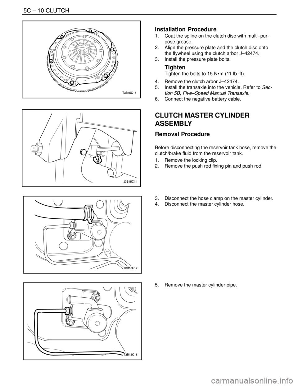
1. Coat the spline on the clutch disc with multi–pur-
pose grease.
2. Align the pressure plate and the clutch disc onto
the flywheel using the clutch arbor J–42474.
3. Install the pressure plate bolts.
Tighten
Tighten the bolts to 15 NSm (11 lb–ft).
4. Remove the clutch arbor J–42474.
5. Install the transaxle into the vehicle. Refer to Sec-
tion 5B, Five–Speed Manual Transaxle.
6. Connect the negative battery cable.
CLUTCH MASTER CYLINDER
ASSEMBLY
Removal Procedure
Before disconnecting the reservoir tank hose, remove the
clutch/brake fluid from the reservoir tank.
1. Remove the locking clip.
2. Remove the push rod fixing pin and push rod.
3. Disconnect the hose clamp on the master cylinder.
4. Disconnect the master cylinder hose.
5. Remove the master cylinder pipe.
Page 1920 of 2643

POWER STEERING GEAR 6C – 3
DAEWOO V–121 BL4
DIAGNOSIS
POWER RACK AND PINION STEERING GEAR
Hissing Noise
ChecksAction
Check the intermediate shaft joints for looseness.Tighten the intermediate shaft joints.
Check the power steering hose for contact with other com-
ponents.Be sure the power steering hose is correctly fitted into the
hose clips.
Rattling Noise in Steering Gear
ChecksAction
Check the power steering hose for contact with the body.Be sure the power steering hose is correctly fitted into the
hose clips.
Check the steering gear for insufficient lubrication.Lubricate the steering gear.
Check the steering gear mounting for improper installa-
tion.Tighten the steering gear mounting bracket nuts and bolts.
Check the outer tie rods for improper installation.Tighten the outer tie rod joints. Replace the outer tie rods.
Poor Return of Steering Wheel to Center
ChecksAction
Check the steering wheel for contact with the turn signal
housing.Adjust the turn signal housing.
Check the intermediate shaft joints for binding or loose-
ness.Replace the intermediate shaft.
Check the power steering pump flow control valve for
sticking and improper alignment.Replace the power steering pump.
Check the wheel alignment.Align the wheels.
Check the wheel bearings for wear or damage.Replace the wheel bearings.
Check the intermediate shaft joints for improper installa-
tion.Adjust the intermediate shaft between the steering gear
and the steering column.
Replace the intermediate shaft.
Check the outer tie rods and the ball joints for binding or
looseness.Tighten the tie rods and the ball joints. Replace the tie rods
and the ball joints.
Check the steering gear adjustments.Perform a straight–ahead check.
Check the steering column shaft seal for rubbing on the
shaft.Replace the dash seal.
Check the steering shaft bearings for binding.Replace the stub shaft bearings.
Momentary Increase in Effort When Turning the Wheel Quickly
ChecksAction
Check the power steering pump for internal leaks.Replace the power steering pump.
Check the hoses for damage or restricted flow.Replace the power steering hoses and/or pipes.
Check the power steering fluid level.Fill the power steering fluid reservoir.
Check the power steering pump flow control valve for
sticking and improper operation.Replace the power steering pump.
Page 1921 of 2643

6C – 4IPOWER STEERING GEAR
DAEWOO V–121 BL4
Steering Surges or Jerks When Turning with Engine Running
ChecksAction
Check the power steering pump for insufficient pressure.Replace the power steering pump.
Check the power steering pump flow control valve for
sticking and improper operation.Replace the power steering pump.
Check the power steering pump serpentine belt for slip-
page.Tighten the power steering serpentine belt.
Check for air contamination in the power steering system.Bleed the power steering system.
Steering Vibrates During Low Speed or Static Steering
ChecksAction
Check for air contamination in the power steering system.Bleed the power steering system.
Check the power steering pump serpentine belt for loose-
ness.Tighten the power steering serpentine belt.
Excessive Wheel Kickback or Loose Steering
ChecksAction
Check for air contamination in the power steering system.Bleed the power steering system.
Check the wheel bearings for wear or damage.Replace the wheel bearings.
Check the steering gear mounting for improper installa-
tion.Tighten the steering gear mounting bracket nuts and bolts.
Check the intermediate shaft joints for improper installa-
tion.Adjust the intermediate shaft between the steering gear
and the steering column.
Replace the intermediate shaft.
Check the outer tie rods and ball joints for looseness.Tighten the tie rods and the ball joints. Replace the tie rods
and the ball joints.
Hard Steering or Lack of Assist (Especially During Parking)
ChecksAction
Adjust the intermediate shaft between the steering gear
and the steering column. Replace the coupling flange.Adjust the steering coupling flange on the steering gear
and the steering column. Replace the coupling flange as
needed.
Check the power steering pump flow control valve for
sticking and improper installation.Replace the power steering pump.
Check the power steering pump for insufficient pressure.Replace the power steering pump.
Check the power steering pump for internal leaks.Replace the power steering pump.
Check for a loose or a worn intermediate shaft.Tighten the intermediate shaft. Replace the intermediate
shaft as needed.
Check the power steering pump serpentine belt tension.Tighten the power steering serpentine belt.
Page 1929 of 2643
6C – 12IPOWER STEERING GEAR
DAEWOO V–121 BL4
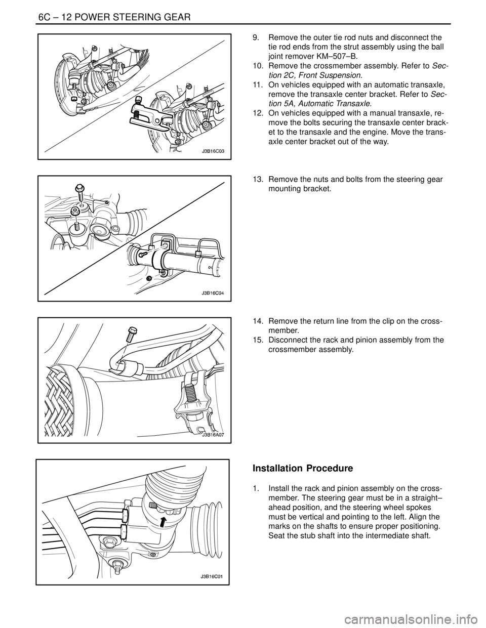
9. Remove the outer tie rod nuts and disconnect the
tie rod ends from the strut assembly using the ball
joint remover KM–507–B.
10. Remove the crossmember assembly. Refer to Sec-
tion 2C, Front Suspension.
11. On vehicles equipped with an automatic transaxle,
remove the transaxle center bracket. Refer to Sec-
tion 5A, Automatic Transaxle.
12. On vehicles equipped with a manual transaxle, re-
move the bolts securing the transaxle center brack-
et to the transaxle and the engine. Move the trans-
axle center bracket out of the way.
13. Remove the nuts and bolts from the steering gear
mounting bracket.
14. Remove the return line from the clip on the cross-
member.
15. Disconnect the rack and pinion assembly from the
crossmember assembly.
Installation Procedure
1. Install the rack and pinion assembly on the cross-
member. The steering gear must be in a straight–
ahead position, and the steering wheel spokes
must be vertical and pointing to the left. Align the
marks on the shafts to ensure proper positioning.
Seat the stub shaft into the intermediate shaft.