Page 993 of 2643
3A – 4IAUTOMATIC TRANSAXLE DRIVE AXLE
DAEWOO V–121 BL4
MAINTENANCE AND REPAIR
ON–VEHICLE SERVICE
DRIVE AXLE ASSEMBLY
Tools Required
KM–507–B Ball Joint Separator
DW340–110 Axle Shaft Remover
Removal Procedure
1. Raise and suitably support the vehicle.
2. Remove the wheels. Refer to Section 2E, Tires
and Wheels.
3. Remove the axle shaft caulking nut. Discard the
nut.
Notice : Use only the recommended tool for separating
the lower ball joint. Failure to use the recommended tool
may cause damage to the ball joint and the seal.
4. Remove the lower ball joint pinch bolt and nut.
5. Separate the steering knuckle from the lower ball
joint using the ball joint separator KM–507–B.
6. Remove the tie rod nut.
Notice : Use only the recommended tool for separating
the tie rod from the knuckle/strut assembly. Failure to use
the recommended tool may cause damage to the knuckle/
strut assembly.
7. Separate the tie rod end using the ball joint separa-
tor KM–507–B.
Page 1004 of 2643
MANUAL TRANSAXLE DRIVE AXLE 3B – 5
DAEWOO V–121 BL4
MAINTENANCE AND REPAIR
ON–VEHICLE SERVICE
DRIVE AXLE ASSEMBLY
Tools Required
KM–507–B Ball Joint Separator
KM–460–A Axle Shaft Remover
Removal Procedure
1. Raise and suitably support the vehicle.
2. Remove the wheels. Refer to Section 2E, Tires and
Wheels.
3. Remove the axle shaft caulking nut. Discard the
nut.
Notice : Use only the recommended tool for separating
the lower ball joint. Failure to use the recommended tool
may cause damage to the ball joint and the seal.
4. Remove the lower ball joint pinch bolt and nut.
5. Separate the steering knuckle from the lower ball
joint using the ball joint separator KM–507–B.
6. Remove the tie rod nut.
Notice : Use only the recommended tool for separating
the tie rod from the knuckle/strut assembly. Failure to use
the recommended tool may cause damage to the knuckle/
strut assembly.
7. Separate the tie rod end using the ball joint separa-
tor KM–507–B.
Page 1029 of 2643
HYDRAULIC BRAKES 4A – 13
DAEWOO V–121 BL4
8. Attach the bleeder hose to the bleeder valve. Sub-
merge the opposite end of the hose in a clean con-
tainer partially filled with brake fluid.
9. Open the bleeder valve one–half to three–fourths
turn and allow the fluid to flow until no air is seen in
the fluid.
Notice : After the bleeding operation, the brake reservoir
may be pressurized. While disconnecting the bleeder
hose or the unthreaded adapter cap, cover the cap and the
connection with a shop towel to protect painted surfaces
from contact with the brake fluid.
10. Inspect the brake pedal for sponginess. Repeat the
entire bleeding procedure to correct this condition.
BRAKE HOSE REAR
Removal Procedure
1. Raise and suitably support the vehicle.
2. Remove the brake hose retainer.
3. Disconnect the brake pipe line from the disc brake
hose.
4. Remove the rear disc brake hose retainer and the
brake hose from the bracket on the steering
knuckle shaft.
Page 1030 of 2643

4A – 14IHYDRAULIC BRAKES
DAEWOO V–121 BL4
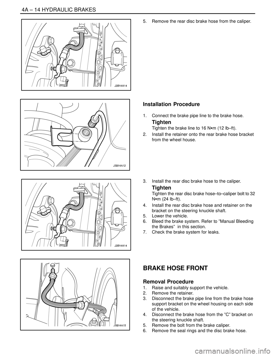
5. Remove the rear disc brake hose from the caliper.
Installation Procedure
1. Connect the brake pipe line to the brake hose.
Tighten
Tighten the brake line to 16 NSm (12 lb–ft).
2. Install the retainer onto the rear brake hose bracket
from the wheel house.
3. Install the rear disc brake hose to the caliper.
Tighten
Tighten the rear disc brake hose–to–caliper bolt to 32
NSm (24 lb–ft).
4. Install the rear disc brake hose and retainer on the
bracket on the steering knuckle shaft.
5. Lower the vehicle.
6. Bleed the brake system. Refer to ”Manual Bleeding
the Brakes” in this section.
7. Check the brake system for leaks.
BRAKE HOSE FRONT
Removal Procedure
1. Raise and suitably support the vehicle.
2. Remove the retainer.
3. Disconnect the brake pipe line from the brake hose
support bracket on the wheel housing on each side
of the vehicle.
4. Disconnect the brake hose from the ”C” bracket on
the steering knuckle shaft.
5. Remove the bolt from the brake caliper.
6. Remove the seal rings and the disc brake hose.
Page 1031 of 2643

HYDRAULIC BRAKES 4A – 15
DAEWOO V–121 BL4
Installation Procedure
1. Install the new disc brake hose to the caliper with
new seal rings and the bolt.
Tighten
Tighten the front disc brake hose–to–caliper bolt to 40
NSm (30 lb–ft).
2. Slide the brake hose on the steering knuckle shaft
”C” bracket.
3. Connect the brake pipe line to the brake hose on
the wheel housing bracket on each side of the ve-
hicle.
Tighten
Tighten the brake line to 16 NSm (12 lb–ft).
4. Lower the vehicle.
5. Bleed the brake system. Refer to ”Manual Bleeding
the Brakes” in this section.
6. Check the brake system for leaks.
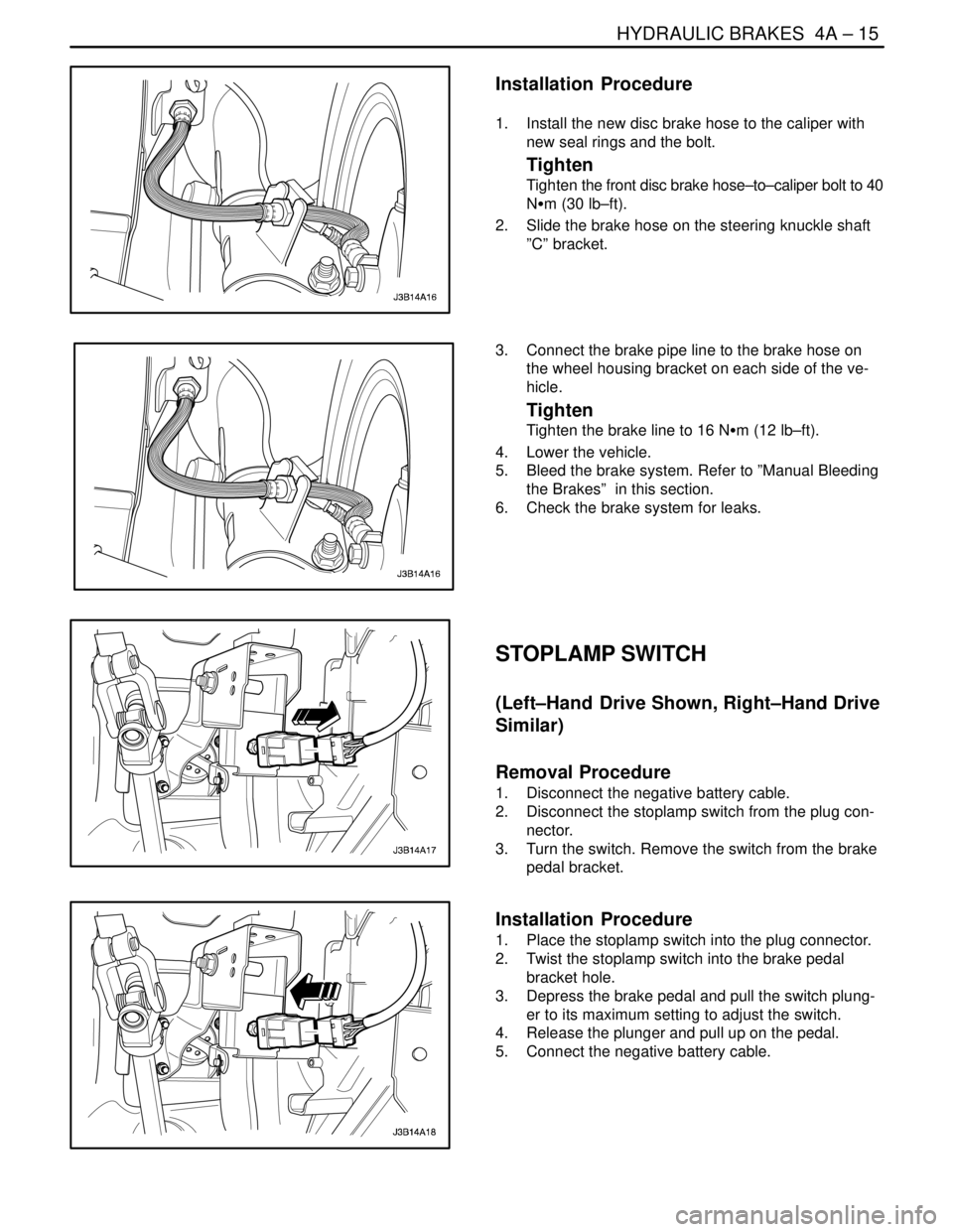
STOPLAMP SWITCH
(Left–Hand Drive Shown, Right–Hand Drive
Similar)
Removal Procedure
1. Disconnect the negative battery cable.
2. Disconnect the stoplamp switch from the plug con-
nector.
3. Turn the switch. Remove the switch from the brake
pedal bracket.
Installation Procedure
1. Place the stoplamp switch into the plug connector.
2. Twist the stoplamp switch into the brake pedal
bracket hole.
3. Depress the brake pedal and pull the switch plung-
er to its maximum setting to adjust the switch.
4. Release the plunger and pull up on the pedal.
5. Connect the negative battery cable.
Page 1049 of 2643

SECTION : 4D
FRONT DISC BRAKES
TABLE OF CONTENTS
SPECIFICATIONS4D–1 . . . . . . . . . . . . . . . . . . . . . . . . . .
Fastener Tightening Specirications 4D–1. . . . . . . . . .
DIAGNOSIS4D–1 . . . . . . . . . . . . . . . . . . . . . . . . . . . . . . . .
Lining Inspection 4D–1. . . . . . . . . . . . . . . . . . . . . . . . . .
Rotor Inspection 4D–1. . . . . . . . . . . . . . . . . . . . . . . . . .
MAINTENANCE AND REPAIR4D–3 . . . . . . . . . . . . . . .
ON–VEHICLE SERVICE 4D–3. . . . . . . . . . . . . . . . . . . . .
Shoe and Lining 4D–3. . . . . . . . . . . . . . . . . . . . . . . . . . Caliper Assembly 4D–3. . . . . . . . . . . . . . . . . . . . . . . . . .
Rotor 4D–4. . . . . . . . . . . . . . . . . . . . . . . . . . . . . . . . . . . .
Splash Shield 4D–5. . . . . . . . . . . . . . . . . . . . . . . . . . . . .
UNIT REPAIR 4D–6. . . . . . . . . . . . . . . . . . . . . . . . . . . . . .
Caliper Overhaul 4D–6. . . . . . . . . . . . . . . . . . . . . . . . . .
GENERAL DESCRIPTION AND SYSTEM
OPERATION4D–9 . . . . . . . . . . . . . . . . . . . . . . . . . . . . . .
Disc Brake Caliper Assembly 4D–9. . . . . . . . . . . . . . . .
SPECIFICATIONS
FASTENER TIGHTENING SPECIRICATIONS
ApplicationNSmLb–FtLb–In
Brake Hose Inlet Fitting–to–Caliper Bolt4030–
Caliper Bleeder Valve8–71
Caliper–to–Steering Knuckle Mounting Bolts9570–
Retaining Frame–to–Caliper Housing Bolts2720–
Rotor–to–Front Wheel Hub Detent Screw4–35
Splash Shield–to–Steering Knuckle Screws4–35
DIAGNOSIS
LINING INSPECTION
1. Raise and suitably support the vehicle.
2. Remove the front wheels. Refer to Section 2E,
Tires and Wheels.
3. Visually check the linings for minimum thickness
and wear.
4. Measure the thickness.
Important : The minimum thickness of the inner or the
outer pad is 7 mm (0.28 inch).
5. Install the brake pads in axle sets only.
6. Install the front wheels. Refer to Section 2E, Tires
and Wheels.
7. Lower the vehicle.ROTOR INSPECTION
Thickness variation can be checked by measuring the
thickness of the rotor at four or more points around the cir-
cumference of the rotor. All measurements must be made
at the same distance in from the edge of the rotor.
A rotor that varies by more than 0.01 mm (0.0004 inch) can
cause pedal pulsations and/or front end vibration during
brake applications. A rotor that does not meet these speci-
fications should be refinished to specifications or re-
placed.
Page 1052 of 2643

4D – 4IFRONT DISC BRAKES
DAEWOO V–121 BL4
Installation Procedure
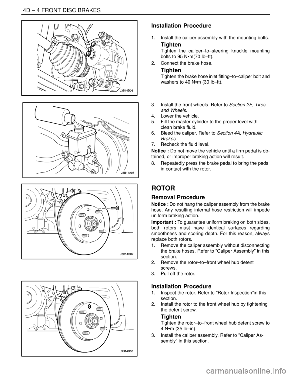
1. Install the caliper assembly with the mounting bolts.
Tighten
Tighten the caliper–to–steering knuckle mounting
bolts to 95 NSm(70 lb–ft).
2. Connect the brake hose.
Tighten
Tighten the brake hose inlet fitting–to–caliper bolt and
washers to 40 NSm (30 lb–ft).
3. Install the front wheels. Refer to Section 2E, Tires
and Wheels.
4. Lower the vehicle.
5. Fill the master cylinder to the proper level with
clean brake fluid.
6. Bleed the caliper. Refer to Section 4A, Hydraulic
Brakes.
7. Recheck the fluid level.
Notice : Do not move the vehicle until a firm pedal is ob-
tained, or improper braking action will result.
8. Repeatedly press the brake pedal to bring the pads
in contact with the rotor.
ROTOR
Removal Procedure
Notice : Do not hang the caliper assembly from the brake
hose. Any resulting internal hose restriction will impede
uniform braking action.
Important : To guarantee uniform braking on both sides,
both rotors must have identical surfaces regarding
smoothness and scoring depth. For this reason, always
replace both rotors.
1. Remove the caliper assembly without disconnecting
the brake hoses. Refer to ”Caliper Assembly” in this
section.
2. Remove the rotor–to–front wheel hub detent
screws.
3. Pull off the rotor.
Installation Procedure
1. Inspect the rotor. Refer to ”Rotor Inspection”in this
section.
2. Install the rotor to the front wheel hub by tightening
the detent screw.
Tighten
Tighten the rotor–to–front wheel hub detent screw to
4 NSm (35 lb–in).
3. Install the caliper assembly. Refer to ”Caliper As-
sembly” in this section.
Page 1053 of 2643
FRONT DISC BRAKES 4D – 5
DAEWOO V–121 BL4
SPLASH SHIELD
Removal Procedure
1. Remove the rotor. Refer to ”Rotor” in this section.
2. Remove the screws for the splash shield from the
steering knuckle.
3. Remove the splash shield.
Installation Procedure
1. Install the splash shield.
2. Secure the splash shield to the steering knuckle
with the screws.
Tighten
Tighten the splash shield–to–steering knuckle screws
to 4 NSm (35 lb–in).
3. Install the rotor. Refer to ”Rotor” in this section.