Page 1692 of 2643
5A2 – 102IAISIN AUTOMATIC TRANSAXLE
DAEWOO V–121 BL4
3. Remove the E–ring.
4. Disconnect the shift control cable from the TR
switch lever.
5. Remove the retaining nut and then remove the
washer and the control lever.
6. Using a driver, unstake the lock washer and re-
move the nut.
Installation Procedure
1. Install the Transmission Range (TR) switch onto the
manual valve lever shaft and temporarily install the
2 adjusting bolts.
2. Install the new lock washer and nuts.
Tighten
Tighten the nuts to 12 NSm (106 Ib–in).
3. Temporarily install the control lever.
4. Turn the lever counterclockwise until it stops, then
turn it clockwise 2 notches.
5. Remove the control lever.
Page 1693 of 2643
AISIN AUTOMATIC TRANSAXLE 5A2 – 103
DAEWOO V–121 BL4
6. Aligh the groove with the neutral basic line, then
install the 2 bolts.
Tighten
Tighten the 2 bolts to 5.4 NSm (48 Ib–in).
7. Using a screw driver, stake the nut with the lock
washer.
8. Install the control lever, washer and nut.
Tighten
Tighten the nut to 12 NSm (106 Ib–in).
9. Connect the control cable to TR switch.
10. Connect the TR switch electrical connector.
11. Adjust the control cable. Refer to ”Control Cable
Adjustment” in this section.
12. Install the control cable adjusting nut.
Tighten
Tighten the control cable adjusting nut to 8 NSm (71
Ib–in).
13. Connect the negative battery cable.
Page 1702 of 2643
5A2 – 112IAISIN AUTOMATIC TRANSAXLE
DAEWOO V–121 BL4
7. Disconnect the input shaft speed (ISS) sensor elec-
trical connector.
8. Disconnect the output shaft speed (OSS) sensor
electrical connector.
9. Disconnect the Transmission Range (TR) Switch
electrical connector.
10. Disconnect the transaxle electrical connector.
11. Remove the service hall cover.
12. Remove the three torque converter bolts.
13. Remove the damping block connection nut and
bolt.
14. Remove the rear mounting bracket bolts and rear
mounting bracket.
15. Remove the three upper transaxle mounting brack-
et bolts.
Page 1705 of 2643
AISIN AUTOMATIC TRANSAXLE 5A2 – 115
DAEWOO V–121 BL4
5. Install the rear mounting bracket bolts and the
bracket.
Tighten
Tighten the rear mounting bracket bolts to 60 NSm (44
Ib–ft).
6. Install the damping block connection nut and bolt.
Tighten
Tighten the damping block connection nut and bolt to
80 NSm (59 Ib–ft).
7. Install the torque converter bolts.
Tighten
Tighten the torque converter bolts to 45 NSm (33 Ib–
ft).
8. Install the service hall cover.
9. Connect the transaxle electrical connector.
10. Connect the TR switch electrical connector.
11. Connect the OSS sensor electrical connector.
12. Connect the ISS sensor electrical connector.
13. Remove engine support fixture DW110–060.
14. Connect the shift control cable into the transaxle.
Refer to ”Shift Control Cable” in this section.
Page 1707 of 2643

AISIN AUTOMATIC TRANSAXLE 5A2 – 117
DAEWOO V–121 BL4
UNIT REPAIR
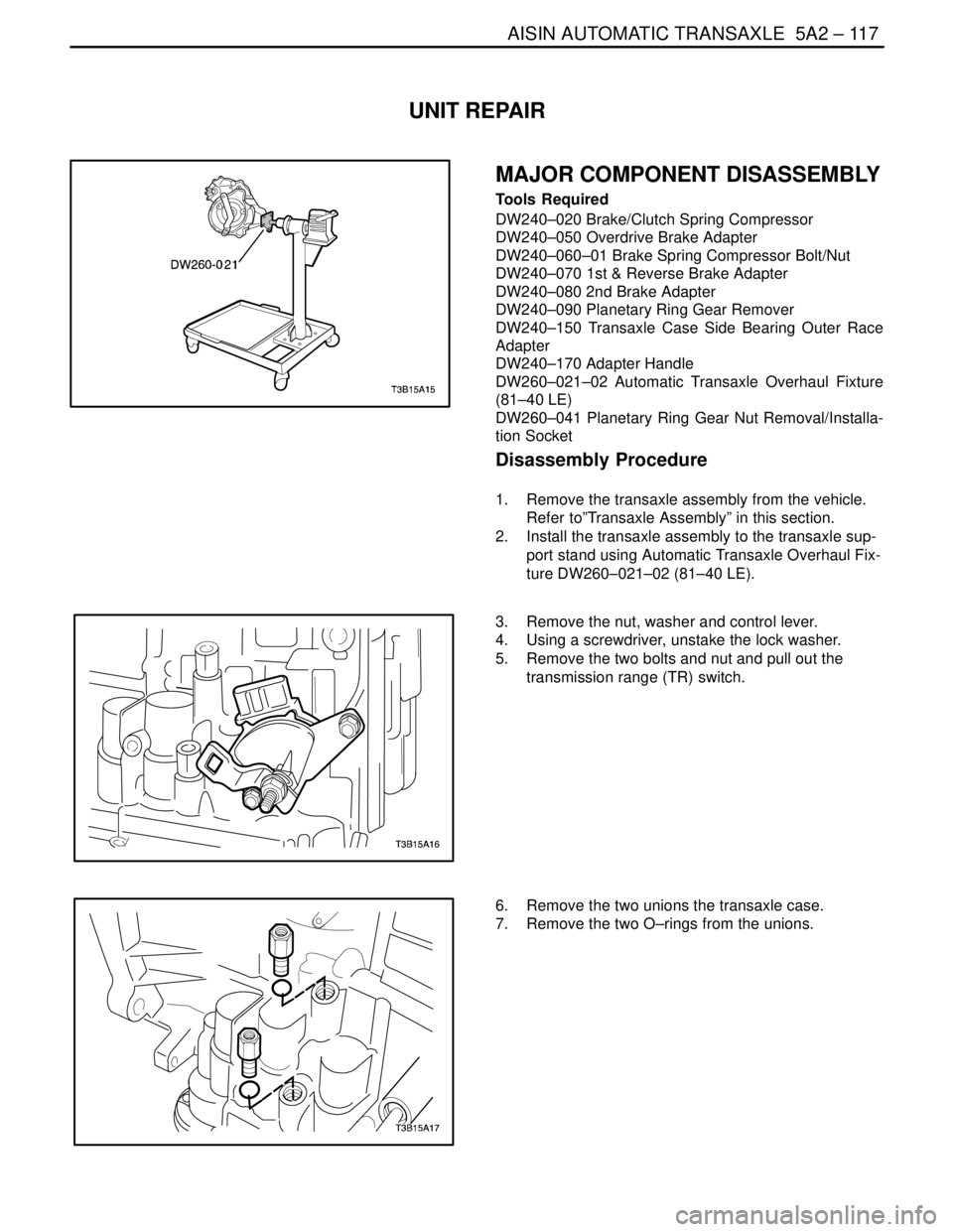
MAJOR COMPONENT DISASSEMBLY
Tools Required
DW240–020 Brake/Clutch Spring Compressor
DW240–050 Overdrive Brake Adapter
DW240–060–01 Brake Spring Compressor Bolt/Nut
DW240–070 1st & Reverse Brake Adapter
DW240–080 2nd Brake Adapter
DW240–090 Planetary Ring Gear Remover
DW240–150 Transaxle Case Side Bearing Outer Race
Adapter
DW240–170 Adapter Handle
DW260–021–02 Automatic Transaxle Overhaul Fixture
(81–40 LE)
DW260–041 Planetary Ring Gear Nut Removal/Installa-
tion Socket
Disassembly Procedure
1. Remove the transaxle assembly from the vehicle.
Refer to”Transaxle Assembly” in this section.
2. Install the transaxle assembly to the transaxle sup-
port stand using Automatic Transaxle Overhaul Fix-
ture DW260–021–02 (81–40 LE).
3. Remove the nut, washer and control lever.
4. Using a screwdriver, unstake the lock washer.
5. Remove the two bolts and nut and pull out the
transmission range (TR) switch.
6. Remove the two unions the transaxle case.
7. Remove the two O–rings from the unions.
Page 1709 of 2643
AISIN AUTOMATIC TRANSAXLE 5A2 – 119
DAEWOO V–121 BL4
17. Remove the three bolts and oil strainer.
18. Remove the gasket from the oil strainer.
19. Remove the bolt and transmission fluid temperature
sensor with the clamp.
20. Disconnect the 5 solenoid connectors.
a. Lock–up control solenoid
b. Pressure control solenoid.
c. No.2 shift solenoid.
d. No.1 shift solenoid.
e. Timing solenoid
21. Support the valve body assembly and remove the
14 bolts.
Page 1719 of 2643
AISIN AUTOMATIC TRANSAXLE 5A2 – 129
DAEWOO V–121 BL4
61. Remove the 2 plates, 2 discs and flange.
62. Remove the No. 2 one–way clutch and planetary
gear from the transaxle case.
63. Remove the No. 2 one–way clutch from the plane-
tary gear and remove the anti–rattle clip.
64. Fix the counter drive gear with the parking lock
pawl.
Page 1720 of 2643
5A2 – 130IAISIN AUTOMATIC TRANSAXLE
DAEWOO V–121 BL4
65. Remove the planetary ring gear nut using planetary
ring gear nut removal/installation socket DW
260–041.
Notice : Remove the nut without unstaking the planetary
ring gear. If chisel or other tool is used to unstake the plan-
etary ring gear, such impact may damage the bearing.
66. Remove the 2 bolts and parking lock pawl bracket.
67. Remove the parking lock pawl shaft, torsion spring
and parking lock pawl.
68. Remove the bolt and manual detent spring.