2004 DAEWOO NUBIRA section 9G
[x] Cancel search: section 9GPage 2048 of 2643

7B – 46IMANUAL CONTROL HEATING, VENTILATION AND AIR CONDITIONING SYSTEM
DAEWOO V–121 BL4
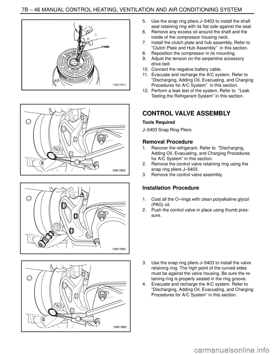
5. Use the snap ring pliers J–5403 to install the shaft
seal retaining ring with its flat side against the seal.
6. Remove any excess oil around the shaft and the
inside of the compressor housing neck.
7. Install the clutch plate and hub assembly. Refer to
”Clutch Plate and Hub Assembly” in this section.
8. Reposition the compressor in its mounting.
9. Adjust the tension on the serpentine accessory
drive belt.
10. Connect the negative battery cable.
11. Evacuate and recharge the A/C system. Refer to
”Discharging, Adding Oil, Evacuating, and Charging
Procedures for A/C System” in this section.
12. Perform a leak test of the system. Refer to ”Leak
Testing the Refrigerant System” in this section.
CONTROL VALVE ASSEMBLY
Tools Required
J–5403 Snap Ring Pliers
Removal Procedure
1. Recover the refrigerant. Refer to ”Discharging,
Adding Oil, Evacuating, and Charging Procedures
for A/C System” in this section.
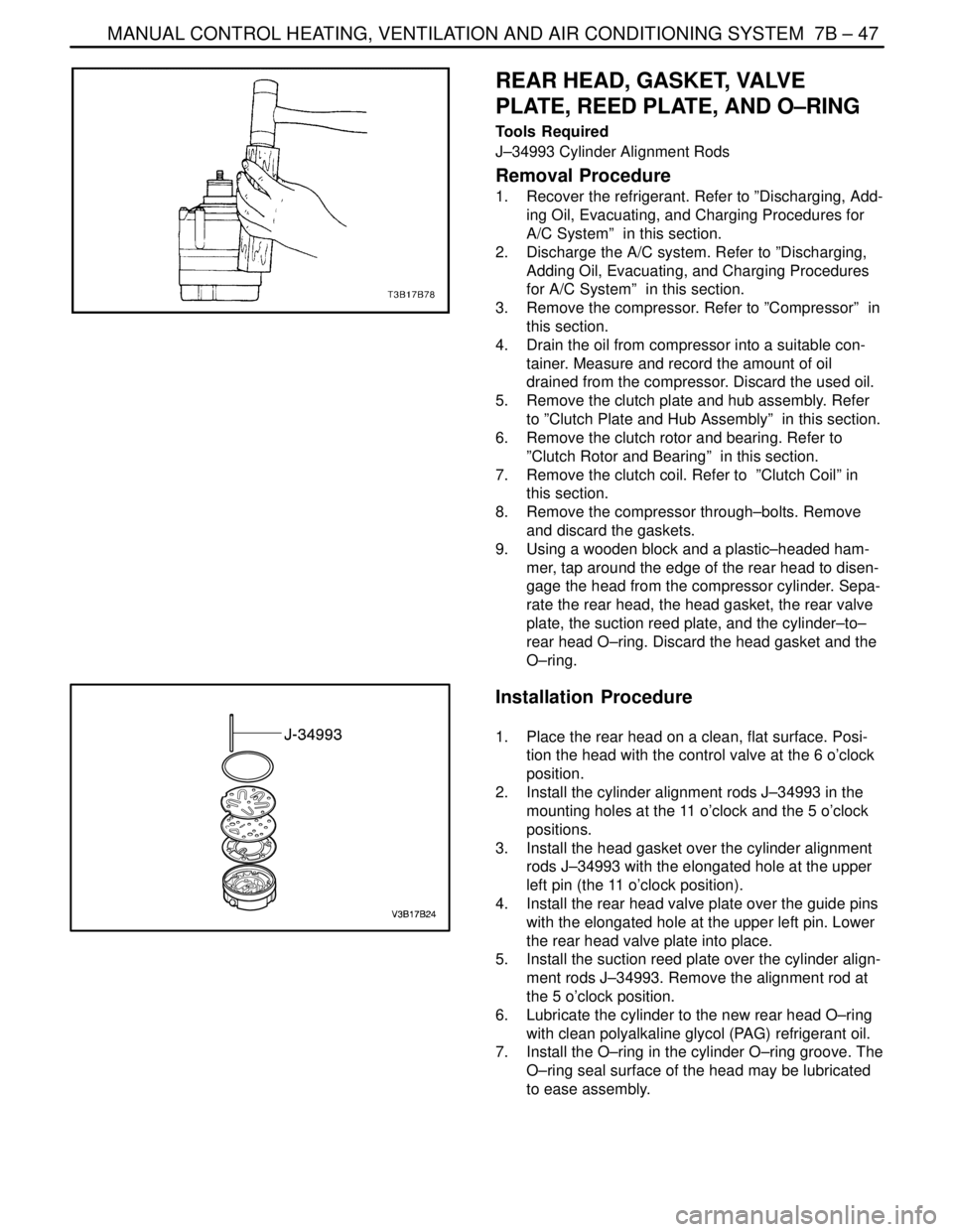
2. Remove the control valve retaining ring using the
snap ring pliers J–5403.
3. Remove the control valve assembly.
Installation Procedure
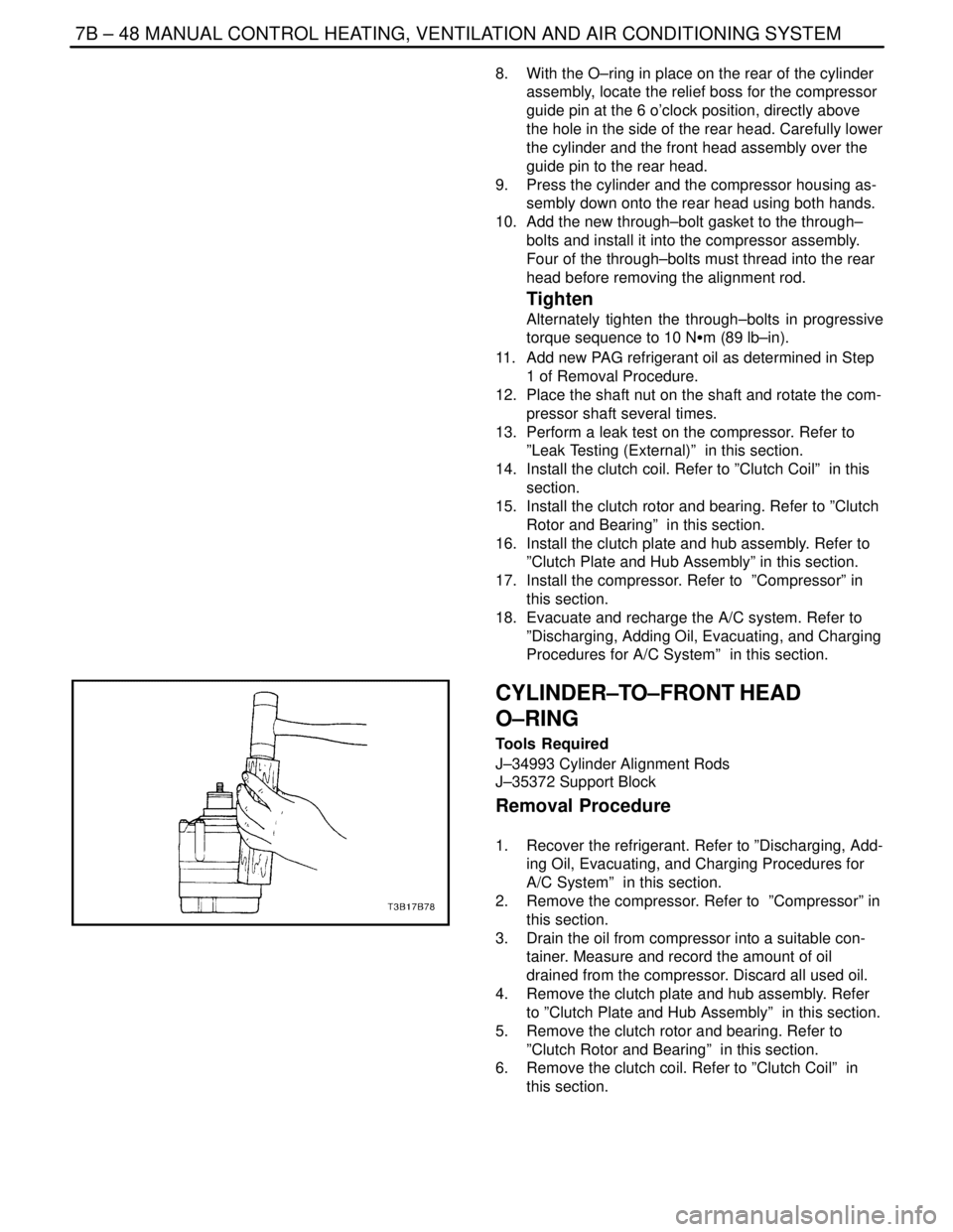
1. Coat all the O–rings with clean polyalkaline glycol
(PAG) oil.
2. Push the control valve in place using thumb pres-
sure.
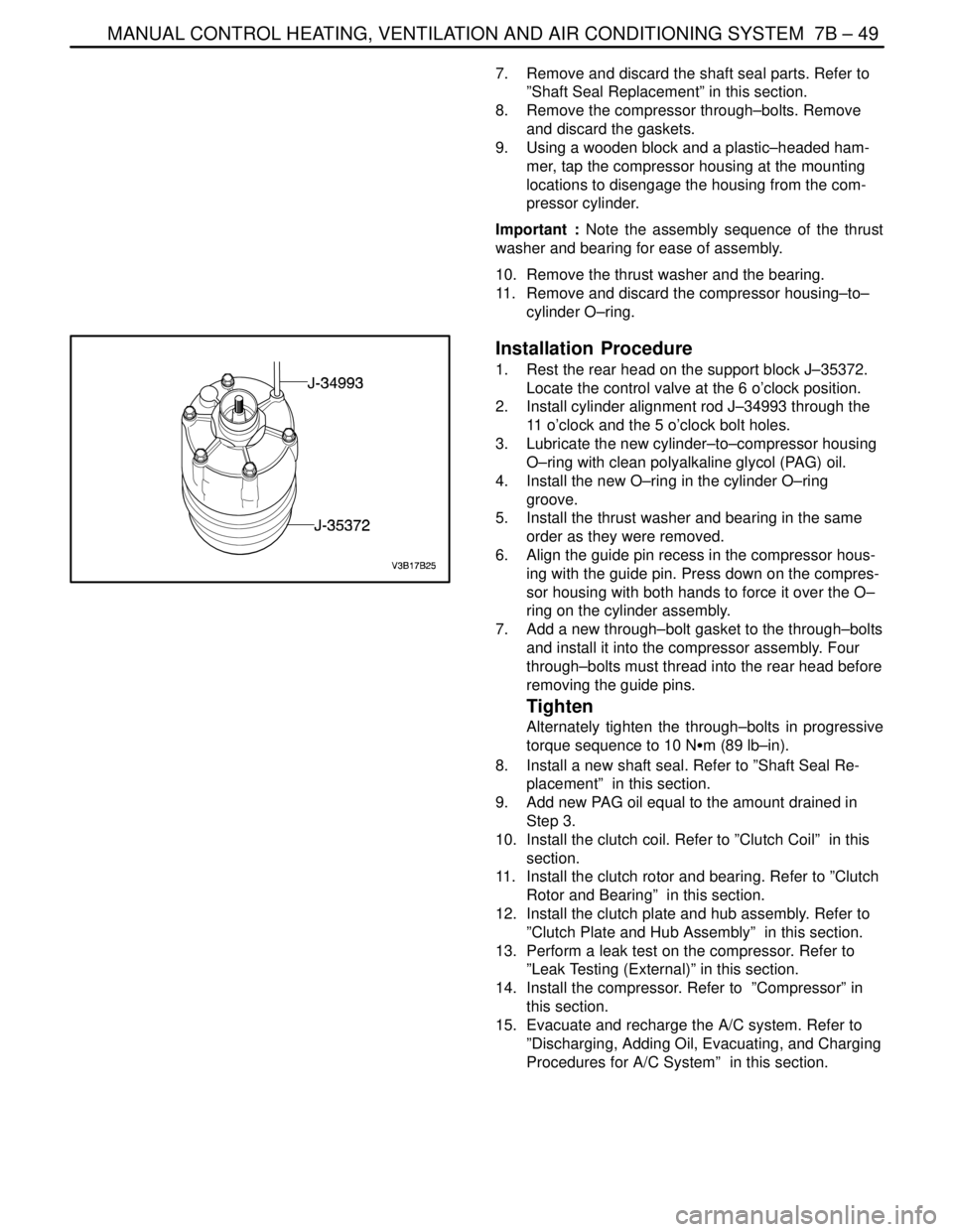
3. Use the snap ring pliers J–5403 to install the valve
retaining ring. The high point of the curved sides
must be against the valve housing. Be sure the re-
taining ring is properly seated in the ring groove.
4. Evacuate and recharge the A/C system. Refer to
”Discharging, Adding Oil, Evacuating, and Charging
Procedures for A/C System” in this section.
Page 2049 of 2643

MANUAL CONTROL HEATING, VENTILATION AND AIR CONDITIONING SYSTEM 7B – 47
DAEWOO V–121 BL4
REAR HEAD, GASKET, VALVE
PLATE, REED PLATE, AND O–RING
Tools Required
J–34993 Cylinder Alignment Rods
Removal Procedure
1. Recover the refrigerant. Refer to ”Discharging, Add-
ing Oil, Evacuating, and Charging Procedures for
A/C System” in this section.
2. Discharge the A/C system. Refer to ”Discharging,
Adding Oil, Evacuating, and Charging Procedures
for A/C System” in this section.
3. Remove the compressor. Refer to ”Compressor” in
this section.
4. Drain the oil from compressor into a suitable con-
tainer. Measure and record the amount of oil
drained from the compressor. Discard the used oil.
5. Remove the clutch plate and hub assembly. Refer
to ”Clutch Plate and Hub Assembly” in this section.
6. Remove the clutch rotor and bearing. Refer to
”Clutch Rotor and Bearing” in this section.
7. Remove the clutch coil. Refer to ”Clutch Coil” in
this section.
8. Remove the compressor through–bolts. Remove
and discard the gaskets.
9. Using a wooden block and a plastic–headed ham-
mer, tap around the edge of the rear head to disen-
gage the head from the compressor cylinder. Sepa-
rate the rear head, the head gasket, the rear valve
plate, the suction reed plate, and the cylinder–to–
rear head O–ring. Discard the head gasket and the
O–ring.
Installation Procedure
1. Place the rear head on a clean, flat surface. Posi-
tion the head with the control valve at the 6 o’clock
position.
2. Install the cylinder alignment rods J–34993 in the
mounting holes at the 11 o’clock and the 5 o’clock
positions.
3. Install the head gasket over the cylinder alignment
rods J–34993 with the elongated hole at the upper
left pin (the 11 o’clock position).
4. Install the rear head valve plate over the guide pins
with the elongated hole at the upper left pin. Lower
the rear head valve plate into place.
5. Install the suction reed plate over the cylinder align-
ment rods J–34993. Remove the alignment rod at
the 5 o’clock position.
6. Lubricate the cylinder to the new rear head O–ring
with clean polyalkaline glycol (PAG) refrigerant oil.
7. Install the O–ring in the cylinder O–ring groove. The
O–ring seal surface of the head may be lubricated
to ease assembly.
Page 2050 of 2643

7B – 48IMANUAL CONTROL HEATING, VENTILATION AND AIR CONDITIONING SYSTEM
DAEWOO V–121 BL4
8. With the O–ring in place on the rear of the cylinder
assembly, locate the relief boss for the compressor
guide pin at the 6 o’clock position, directly above
the hole in the side of the rear head. Carefully lower
the cylinder and the front head assembly over the
guide pin to the rear head.
9. Press the cylinder and the compressor housing as-
sembly down onto the rear head using both hands.
10. Add the new through–bolt gasket to the through–
bolts and install it into the compressor assembly.
Four of the through–bolts must thread into the rear
head before removing the alignment rod.
Tighten
Alternately tighten the through–bolts in progressive
torque sequence to 10 NSm (89 lb–in).
11. Add new PAG refrigerant oil as determined in Step
1 of Removal Procedure.
12. Place the shaft nut on the shaft and rotate the com-
pressor shaft several times.
13. Perform a leak test on the compressor. Refer to
”Leak Testing (External)” in this section.
14. Install the clutch coil. Refer to ”Clutch Coil” in this
section.
15. Install the clutch rotor and bearing. Refer to ”Clutch
Rotor and Bearing” in this section.
16. Install the clutch plate and hub assembly. Refer to
”Clutch Plate and Hub Assembly” in this section.
17. Install the compressor. Refer to ”Compressor” in
this section.
18. Evacuate and recharge the A/C system. Refer to
”Discharging, Adding Oil, Evacuating, and Charging
Procedures for A/C System” in this section.
CYLINDER–TO–FRONT HEAD
O–RING
Tools Required
J–34993 Cylinder Alignment Rods
J–35372 Support Block
Removal Procedure
1. Recover the refrigerant. Refer to ”Discharging, Add-
ing Oil, Evacuating, and Charging Procedures for
A/C System” in this section.
2. Remove the compressor. Refer to ”Compressor” in
this section.
3. Drain the oil from compressor into a suitable con-
tainer. Measure and record the amount of oil
drained from the compressor. Discard all used oil.
4. Remove the clutch plate and hub assembly. Refer
to ”Clutch Plate and Hub Assembly” in this section.
5. Remove the clutch rotor and bearing. Refer to
”Clutch Rotor and Bearing” in this section.
6. Remove the clutch coil. Refer to ”Clutch Coil” in
this section.
Page 2051 of 2643

MANUAL CONTROL HEATING, VENTILATION AND AIR CONDITIONING SYSTEM 7B – 49
DAEWOO V–121 BL4
7. Remove and discard the shaft seal parts. Refer to
”Shaft Seal Replacement” in this section.
8. Remove the compressor through–bolts. Remove
and discard the gaskets.
9. Using a wooden block and a plastic–headed ham-
mer, tap the compressor housing at the mounting
locations to disengage the housing from the com-
pressor cylinder.
Important : Note the assembly sequence of the thrust
washer and bearing for ease of assembly.
10. Remove the thrust washer and the bearing.
11. Remove and discard the compressor housing–to–
cylinder O–ring.
Installation Procedure
1. Rest the rear head on the support block J–35372.
Locate the control valve at the 6 o’clock position.
2. Install cylinder alignment rod J–34993 through the
11 o’clock and the 5 o’clock bolt holes.
3. Lubricate the new cylinder–to–compressor housing
O–ring with clean polyalkaline glycol (PAG) oil.
4. Install the new O–ring in the cylinder O–ring
groove.
5. Install the thrust washer and bearing in the same
order as they were removed.
6. Align the guide pin recess in the compressor hous-
ing with the guide pin. Press down on the compres-
sor housing with both hands to force it over the O–
ring on the cylinder assembly.
7. Add a new through–bolt gasket to the through–bolts
and install it into the compressor assembly. Four
through–bolts must thread into the rear head before
removing the guide pins.
Tighten
Alternately tighten the through–bolts in progressive
torque sequence to 10 NSm (89 lb–in).
8. Install a new shaft seal. Refer to ”Shaft Seal Re-
placement” in this section.
9. Add new PAG oil equal to the amount drained in
Step 3.
10. Install the clutch coil. Refer to ”Clutch Coil” in this
section.
11. Install the clutch rotor and bearing. Refer to ”Clutch
Rotor and Bearing” in this section.
12. Install the clutch plate and hub assembly. Refer to
”Clutch Plate and Hub Assembly” in this section.
13. Perform a leak test on the compressor. Refer to
”Leak Testing (External)” in this section.
14. Install the compressor. Refer to ”Compressor” in
this section.
15. Evacuate and recharge the A/C system. Refer to
”Discharging, Adding Oil, Evacuating, and Charging
Procedures for A/C System” in this section.
Page 2053 of 2643

MANUAL CONTROL HEATING, VENTILATION AND AIR CONDITIONING SYSTEM 7B – 51
DAEWOO V–121 BL4
GENERAL DESCRIPTION
AND SYSTEM OPERATION
GENERAL INFORMATION
THE V5 A/C SYSTEM
The V5 variable displacement compressor along with the
thermal expansion valve on the evaporator, constitutes a
largely self–regulating system. There is no pressure cycl-
ing switch, no high–pressure cut–off switch and no low–
pressure cut–off switch. The compressor clutch is con-
trolled by the electronic control module (ECM), which
receives data from various engine systems and from a
pressure transducer located in the high–pressure refriger-
ant pipe. In normal operation, the clutch is engaged contin-
uously. Should one of the monitored conditions become
abnormal, the ECM will disengage the compressor clutch
until normal operation is restored. These conditions in-
clude the following:
S Wide–open throttle.
S High engine coolant temperature.
S High engine RPM.
S Refrigerant low pressure.
S Refrigerant high pressure.
The compressor clutch will remain disengaged until nor-
mal operation is established.
SYSTEM
COMPONENTS–FUNCTIONAL
Compressor
All compressors are belt–driven from the engine crank-
shaft through the compressor clutch pulley. The compres-
sor pulley rotates without driving the compressor shaft un-
til an electromagnetic clutch coil is energized. When
voltage is applied to energize the clutch coil, the clutch
plate and hub assembly is drawn rearward toward the
pulley. The magnetic force locks the clutch plate and
pulley together as one unit to drive the compressor shaft.
As the compressor shaft is driven, it compresses the low–
pressure refrigerant vapor from the evaporator into a
high–pressure, high–temperature vapor. The refrigerant
oil which is used to lubricate the compressor is carried with
the refrigerant. Refer to ”V5 Air Conditioning Compressor
Overhaul” in this section.
Condenser Core
The condenser assembly in front of the radiator consists
of coils which carry the refrigerant, and cooling fins that
provide the rapid transfer of heat. The air passing through
the condenser cools the high–pressure refrigerant vapor
and causes it to condense into a liquid.
Expansion Valve
The expansion valve is located with the evaporator core,
on the front passenger side fire wall.
The expansion valve can fail in three different positions:
open, closed, or restricted.
An expansion valve that fails in the open position will result
in a noisy A/C compressor or no cooling. The cause can
be a broken spring, a broken ball, or excessive moisture
in the A/C system. If the spring or the ball are found to be
defective, replace the expansion valve. If excessive mois-
ture is found in the A/C system, recycle the refrigerant.
An expansion valve that fails in the closed position will re-
sult in low suction pressure and no cooling. This may be
caused by a failed power dome or excessive moisture in
the A/C system. If the power dome on the expansion valve
is found to be defective, replace the expansion valve. If ex-
cessive moisture is found in the A/C system, recycle the
refrigerant.
A restricted expansion valve will result in low suction pres-
sure and no cooling. This may be caused by debris in the
refrigerant system. If debris is believed to be the cause, re-
cycle the refrigerant, replace the expansion valve, and re-
place the receiver–dryer.
Evaporator Core
The evaporator is a device which cools and dehumidifies
the air before it enters the vehicle. High–pressure liquid re-
frigerant flows through the expansion tube orifice and be-
comes a low–pressure gas in the evaporator. The heat in
the air passing through the evaporator core is transferred
to the cooler surface of the core, which cools the air. As the
process of heat transfer from the air to the evaporator core
surface is taking place, any moisture or humidity in the air
condenses on the outside surface of the evaporator core
and is drained off as water.
Receiver–Dryer
The sealed receiver–dryer assembly is connected to the
condenser outlet pipe. It acts as a refrigerant storing con-
tainer, receiving liquid, vapor, and refrigerant oil from the
evaporator.
At the bottom of the receiver–dryer is the desiccant, which
acts as a drying agent for the moisture that may have en-
tered the system. An oil bleed hole is located near the bot-
tom of the receiver–dryer outlet pipe to provide an oil re-
turn path to the compressor. The receiver–dryer is
serviceable only as an assembly.
Heater Core
The heater core heats the air before it enters the vehicle.
Engine coolant is circulated through the core to heat the
outside air passing over the fins of the core. The core is
functional at all times and may be used to temper condi-
tioned air in the A/C mode as well as in the heat or the vent
modes.
Page 2056 of 2643

SECTION : 7D
AUTOMATIC TEMPERATURE CONTROL
HEATING, VENTILATION, AND AIR
CONDITIONING SYSTEM
CAUTION : Disconnect the negative battery cable before removing or installing any electrical unit or when a tool
or equipment could easily come in contact with exposed electrical terminals. Disconnecting this cable will help
prevent personal injury and damage to the vehicle. The ignition must also be in LOCK unless otherwise noted.
TABLE OF CONTENTS
SPECIFICATIONS7D–2 . . . . . . . . . . . . . . . . . . . . . . . . . .
Fastener Tightening Specifications 7D–2. . . . . . . . . . .
SCHEMATIC AND ROUTING DIAGRAMS7D–3 . . . . .
A/C Sensors/Defoggers and A/C Compressor
Controls Diagram 7D–3. . . . . . . . . . . . . . . . . . . . . . . .
A/C Blower and Motor Controls Diagram 7D–4. . . . . .
DIAGNOSIS7D–5 . . . . . . . . . . . . . . . . . . . . . . . . . . . . . . . .
GENERAL A/C DIAGNOSTICS 7D–5. . . . . . . . . . . . . . .
V5 SYSTEM AIR CONDITIONING AND AUTOMATIC
TEMPERATURE CONTROL (ATC) 7D–5. . . . . . . . . .
Self–Diagnostic Circuit Check 7D–5. . . . . . . . . . . . . . .
Automatic Temperature Controller Does Not
Operate When Ignition Is ON 7D–6. . . . . . . . . . . . . .
Controller Does Not Illuminate When Light Switch
Is ON 7D–7. . . . . . . . . . . . . . . . . . . . . . . . . . . . . . . . . .
No Hot Air From Blower 7D–8. . . . . . . . . . . . . . . . . . . .
No Cool Air From Blower 7D–10. . . . . . . . . . . . . . . . . .
Blower Motor Does Not Run At All 7D–12. . . . . . . . . .
Mode Control Do Not Work 7D–14. . . . . . . . . . . . . . . .
Air Source Selection Not Controlled 7D–16. . . . . . . . .
Compressor Magnetic Clutch Does Not
Engage 7D–17. . . . . . . . . . . . . . . . . . . . . . . . . . . . . . . .
DIAGNOSTIC TROUBLE CODES 7D–18. . . . . . . . . . . .
Code 1 – In–Car Sensor Error 7D–18. . . . . . . . . . . . .
Code 2 – Ambient Air Temperature Sensor
Error 7D–20. . . . . . . . . . . . . . . . . . . . . . . . . . . . . . . . . .
Code 3 – Water Sensor Error 7D–22. . . . . . . . . . . . . . .
Code 4 – Air Mix Door Error 7D–24. . . . . . . . . . . . . . . . Code 5 – Sun Sensor Error 7D–27. . . . . . . . . . . . . . . .
Code 6 – Power Transistor Error 7D–29. . . . . . . . . . . .
Code 7 – Max–Hi Relay Error 7D–31. . . . . . . . . . . . . .
MAINTENANCE AND REPAIR7D–32 . . . . . . . . . . . . . .
ON–VEHICLE SERVICE 7D–32. . . . . . . . . . . . . . . . . . . .
GENERAL A/C SYSTEM SERVICE
PROCEURES 7D–32. . . . . . . . . . . . . . . . . . . . . . . . . . . .
General Service Procedures 7D–32. . . . . . . . . . . . . . .
SERVICEABLE COMPONENTS 7D–33. . . . . . . . . . . . .
Common HVAC Components 7D–33. . . . . . . . . . . . . . .
Automatic Temperature Control Assembly 7D–33. . . .
Inlet Air Door Motor 7D–34. . . . . . . . . . . . . . . . . . . . . . .
Mode Door Motor 7D–35. . . . . . . . . . . . . . . . . . . . . . . . .
Air Mix Door Motor 7D–35. . . . . . . . . . . . . . . . . . . . . . . .
Water Sensor 7D–36. . . . . . . . . . . . . . . . . . . . . . . . . . . .
Ambient Air Temperature Sensor 7D–36. . . . . . . . . . .
In–Car Temperature Sensor 7D–37. . . . . . . . . . . . . . . .
Sun Sensor 7D–37. . . . . . . . . . . . . . . . . . . . . . . . . . . . . .
UNIT REPAIR 7D–39. . . . . . . . . . . . . . . . . . . . . . . . . . . . .
V5 AIR CONDITIONING COMPRESSOR
OVERHAUL 7D–39. . . . . . . . . . . . . . . . . . . . . . . . . . . . .
Compressor Overhaul 7D–39. . . . . . . . . . . . . . . . . . . . .
GENERAL DESCRIPTION AND SYSTEM
OPERATION7D–40 . . . . . . . . . . . . . . . . . . . . . . . . . . . . .
GENERAL INFORMATION 7D–40. . . . . . . . . . . . . . . . . .
The V5 System 7D–40. . . . . . . . . . . . . . . . . . . . . . . . . . .
System Components – Control 7D–40. . . . . . . . . . . . .
Page 2060 of 2643

AUTOMATIC TEMPERATURE CONTROL HEATING, VENTILATION, AND AIR CONDITIONING SYSTEM 7D – 5
DAEWOO V–121 BL4
DIAGNOSIS
GENERAL A/C DIAGNOSTICS
Refer to Section 7B, Manual Control Heating, Ventilation,
and Air Conditioning System for details of the following
procedures:
S A/C Performance Test.
S Insufficient Cooling ”Quick Check” Procedure.
S Insufficient Cooling Diagnosis.S Leak Testing the Refrigerant System.
S Low– and High–Side Pressure Relationship Chart.
S Pressure Test Chart (R–134a System).
S Pressure–Temperature Relationship of R–134a.
S Testing the Refrigerant System.
V5 SYSTEM AIR CONDITIONING AND AUTOMATIC
TEMPERATURE CONTROL (ATC)
SELF–DIAGNOSTIC CIRCUIT CHECK
The Daewoo fully automatic temperature controller
(FATC) contains a self–diagnosis function to aid in finding
any problem with the system. To enter the diagnostic
mode, perform the following procedure:
1. Turn the ignition to ON.
2. Set the temperature control to 26°C (79°F).3. Within 3 seconds, push the AUTO and the OFF
switches simultaneously, more than three times.
4. Count the number of times the temperature indica-
tor screen blinks.
5. If there are no error codes set, the screen will not
blink. When the controller indicates an error code,
proceed to the table for that code.
6. Push the OFF switch to return the controller to its
normal functions.
Page 2062 of 2643

AUTOMATIC TEMPERATURE CONTROL HEATING, VENTILATION, AND AIR CONDITIONING SYSTEM 7D – 7
DAEWOO V–121 BL4
CONTROLLER DOES NOT ILLUMINATE WHEN LIGHT
SWITCH IS ON
StepActionValue(s)YesNo
1Check other instrumentation lights.
Are those lights also off?–Go to Section
9E, Instrumen-
tation/Driver In-
formationGo to Step 2
21. Remove the controller.
2. Check the voltage between terminals A3 and
A4 of the controller connector.
Is the voltage within the specified value?11–14 vGo to Step 4Go to Step 3
3Repair the wiring harness between splice S204 and
controller connector terminal A4 or between splice
S203 and controller connector terminal A3.
Is the repair complete?–System OK–
4Check the illumination lamps.
Is one burned out?–Go to Step 5Go to Step 6
5Replace the burned out illumination lamp.
Is the repair complete?–System OK–