2004 DAEWOO NUBIRA roof
[x] Cancel search: roofPage 2457 of 2643
9Q – 8IROOF
DAEWOO V–121 BL4
Installation Procedure
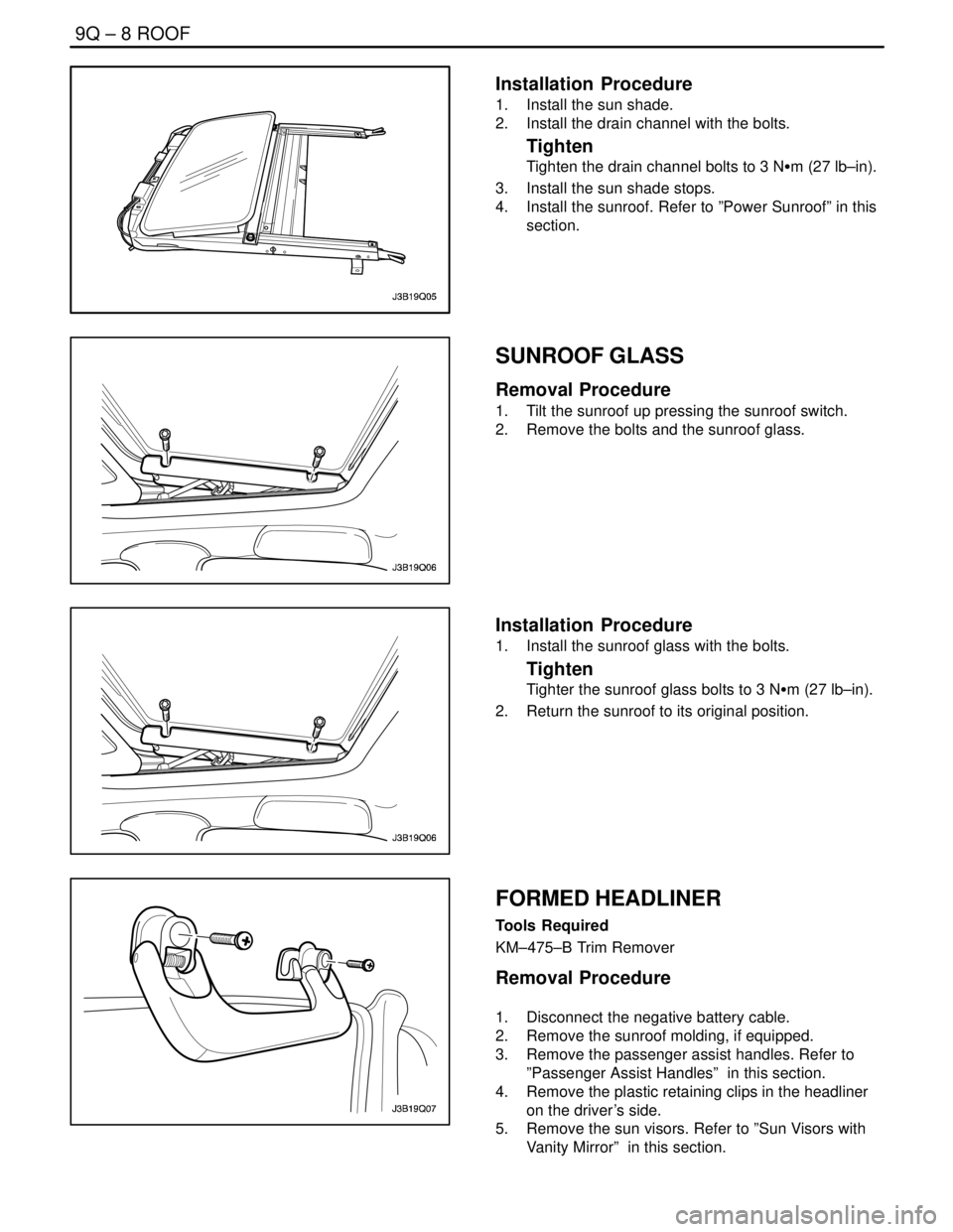
1. Install the sun shade.
2. Install the drain channel with the bolts.
Tighten
Tighten the drain channel bolts to 3 NSm (27 lb–in).
3. Install the sun shade stops.
4. Install the sunroof. Refer to ”Power Sunroof” in this
section.
SUNROOF GLASS
Removal Procedure
1. Tilt the sunroof up pressing the sunroof switch.
2. Remove the bolts and the sunroof glass.
Installation Procedure
1. Install the sunroof glass with the bolts.
Tighten
Tighter the sunroof glass bolts to 3 NSm (27 lb–in).
2. Return the sunroof to its original position.
FORMED HEADLINER
Tools Required
KM–475–B Trim Remover
Removal Procedure
1. Disconnect the negative battery cable.
2. Remove the sunroof molding, if equipped.
3. Remove the passenger assist handles. Refer to
”Passenger Assist Handles” in this section.
4. Remove the plastic retaining clips in the headliner
on the driver’s side.
5. Remove the sun visors. Refer to ”Sun Visors with
Vanity Mirror” in this section.
Page 2458 of 2643
ROOF 9Q – 9
DAEWOO V–121 BL4
6. Remove the power sunroof control switch, if
equipped. Refer to ”Power Sunroof Control Switch”
in this section.
7. Remove the A–, B–, and C–pillar trim panels. Refer
to Section 9G, Interior Trim.
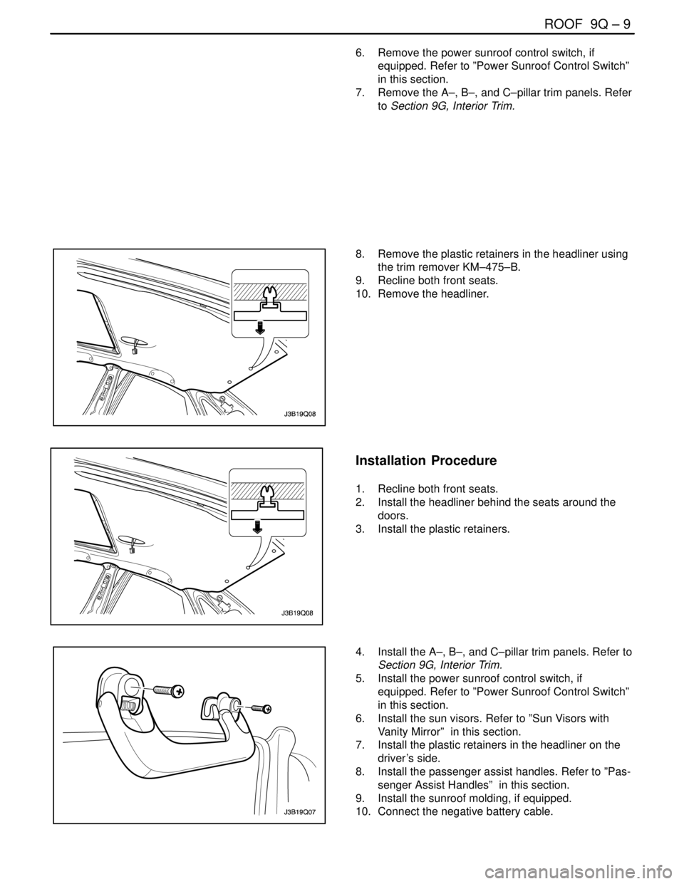
8. Remove the plastic retainers in the headliner using
the trim remover KM–475–B.
9. Recline both front seats.
10. Remove the headliner.
Installation Procedure
1. Recline both front seats.
2. Install the headliner behind the seats around the
doors.
3. Install the plastic retainers.
4. Install the A–, B–, and C–pillar trim panels. Refer to
Section 9G, Interior Trim.
5. Install the power sunroof control switch, if
equipped. Refer to ”Power Sunroof Control Switch”
in this section.
6. Install the sun visors. Refer to ”Sun Visors with
Vanity Mirror” in this section.
7. Install the plastic retainers in the headliner on the
driver’s side.
8. Install the passenger assist handles. Refer to ”Pas-
senger Assist Handles” in this section.
9. Install the sunroof molding, if equipped.
10. Connect the negative battery cable.
Page 2459 of 2643
9Q – 10IROOF
DAEWOO V–121 BL4
SUN VISORS WITH VANITY MIRROR
Removal Procedure
1. Remove the screws and the sun visor from the
headliner.
2. Disconnect the vanity mirror electrical connector.
Refer to Section 9B, Lighting System.
3. Remove the screw and the sun visor support from
the headliner.
Installation Procedure
Notice : Dissimilar metals in direct contact with each other
may corrode rapidly. Make sure to use the correct fasten-
ers to prevent premature corrosion.
1. Install the sun visor support to the headliner with
the screw.
Tighten
Tighten the sun visor support screw to 1.5 NSm (13 lb–
in).
2. Connect the vanity mirror electrical connector. Re-
fer to Section 9B, Lighting System.
3. Install the sun visor to the headliner with the
screws.
Tighten
Tighten the sun ivsor screws to 4 NSm (35 lb–in).
PASSENGER ASSIST HANDLES
Removal Procedure
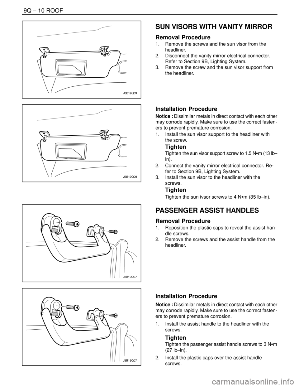
1. Reposition the plastic caps to reveal the assist han-
dle screws.
2. Remove the screws and the assist handle from the
headliner.
Installation Procedure
Notice : Dissimilar metals in direct contact with each other
may corrode rapidly. Make sure to use the correct fasten-
ers to prevent premature corrosion.
1. Install the assist handle to the headliner with the
screws.
Tighten
Tighten the passenger assist handle screws to 3 NSm
(27 lb–in).
2. Install the plastic caps over the assist handle
screws.
Page 2460 of 2643
ROOF 9Q – 11
DAEWOO V–121 BL4
POWER SUNROOF CONTROL
SWITCH
Removal Procedure
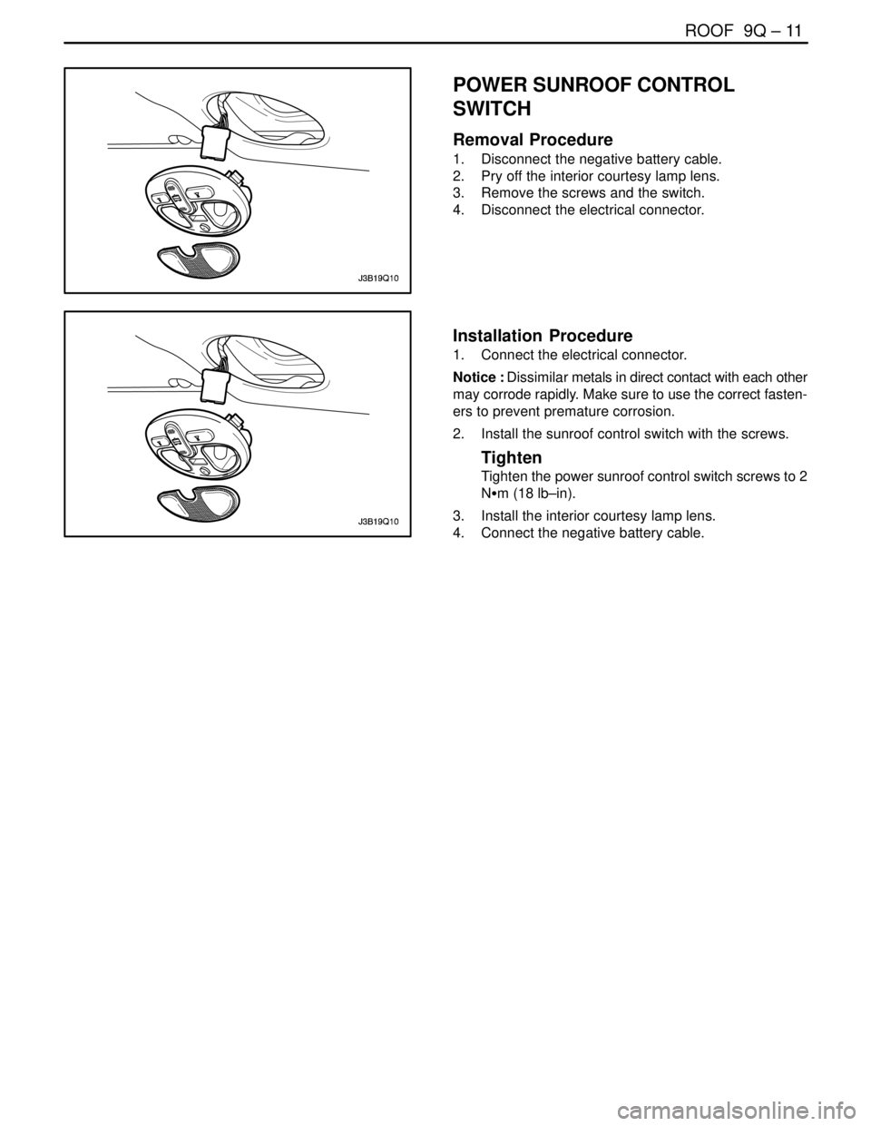
1. Disconnect the negative battery cable.
2. Pry off the interior courtesy lamp lens.
3. Remove the screws and the switch.
4. Disconnect the electrical connector.
Installation Procedure
1. Connect the electrical connector.
Notice : Dissimilar metals in direct contact with each other
may corrode rapidly. Make sure to use the correct fasten-
ers to prevent premature corrosion.
2. Install the sunroof control switch with the screws.
Tighten
Tighten the power sunroof control switch screws to 2
NSm (18 lb–in).
3. Install the interior courtesy lamp lens.
4. Connect the negative battery cable.
Page 2461 of 2643
9Q – 12IROOF
DAEWOO V–121 BL4
GENERAL DESCRIPTION
AND SYSTEM OPERATION
ROOF
The roof is a one–piece painted metal unit which incorpo-
rates a single solid headliner. There are two moldings, one
per side on the vehicle’s roof, which enclose and hide the
roof rail seams. The roof moldings are serviceable as indi-
vidual units.
The one–piece formed headliner consists of a molded
substrate covered with a foam–backed cloth facing. The
one–piece construction requires that the headliner be ser-
viced as a complete assembly.
POWER SUNROOF/SUNROOF
CONTROL SWITCH
The sunroof has the following characteristics:
S Intended to provide light and air through the roof
the vehicle.
S Built into the roof.
S Made of glass.
S Equipped with a sunshade that opens and closes
manually.
S Powered by an electric motor.
S Controlled by a toggle switch built into the interior
courtesy lamp assembly.
The sunroof control switch is a toggle button located on the
right side of the interior courtesy lamp assembly.
To operate the sunroof, the ignition must be ON.Tilting the Sunroof, Open and Closed
To tilt open the rear end of the sunroof, press and hold the
forward portion of the toggle button until the sunroof tilts
open.
To close the sunroof from a tilted–open position, press and
hold the rear portion of the toggle button until the sunroof
tilts closed.
Sliding the Sunroof, Open and Closed
To slide open the sunroof, press the rear portion of the
toggle button until the sunroof slides. If the sun shade is
closed, the sunroof will pull the sunshade open when the
sunroof slides open.
To close the sunroof from a slid–open position, press the
forward portion of the toggle button until the sunroof slides
closed.
SUN VISORS WITH VANITY MIRROR
The sun visors swing down in order to block out glare.
They also swing to the side when they are released from
the support. To replace the vanity mirror lamp, refer to
Section 9B, Lighting Systems.
PASSENGER ASSIST HANDLES
There is a passenger assist handle for each rear outboard
seat and for the front passenger seat. Passengers can use
these handles to assist in keeping their balance over rough
roads or during sharp turns.
COAT HOOKS
The coat hooks are located on the left and the right rear
passenger assist handles.
Page 2510 of 2643
1–2 GENERAL INFORMATIONNUBIRA/LACETTI
1. GENERAL INSTRUCTION
This publication is designed to help you the body repair
technician with your specialized work. Vehicle bodywork
has changed a great deal over the years. As vehicles
have developed technically, vehicle bodywork has also
had to meet new requirements with design, changes to
reconcile apparently conflicting demands to name just a
few examples:
S strength and safety ; low weight
S spaciousness ; good aerodynamices
S high quality ; low price
.
The durability and ease of repair of the bodywork also
plays an important part.
.
Nowadays, the use of highly automated production
equipment makes it possible to maintain the tightest
tolerances and thus ensure a high level of quality.
.
When bodywork is damaged, the customer rightly ex-
pects it to be expertly repaired to the same quality stan-
dards.
.
At the same time, for his safety, the customer expects
you to have comprehensive knowledge of materials,
measuring and straightening methods, possible distor-
tion, optimum corrosion prevention and much more be-
sides.
.
This publication is designed to help you update your
knowledge and give you an idea of what you require to
rectify moderate or severe accident damage, for your
own safety and for the satisfaction of your customers.
2. IMPORTANT SAFETY NOTICE
2–1. BEFORE BEGINNING WORK
S Disconnect the battery to reduce the possibility of fire
caused by electrical shorts.
S Check for fuel leaks and repair as necessary.
S Remove the fuel tank and/or fuel lines if welding equip-
ment is to be used near the fuel system.
S Before welding, sanding or cutting, protect carpets and
seats with fire–proof covers.
S Follow standard safety practices when using toxic or
flammable liquids.
S Use standard safety equipment when spraying paint,
welding, cutting, sanding or grinding. Standard safety
equipment includes.
S Respirator and filter masks: Designed to filter out toxic
fumes, mist, dust or other airborn particles. Use a respi-
rator or filter mask designed to protect you from the haz-
ards of the particular job; some respirators, for example,
are designed to filter out only dust and airborn particles,
not toxic fumes.
S Safety goggles or glasses: Designed to protect your
eyes from projectiles, dust particles or splashing liquid.
S Gloves: Rubber gloves protect against corrosive chemi-
cals. Welding gloves protect against burns and abra-
sions caused by welding, sanding or grinding.
S Safety shoes: Non–slip soles protect against slipping.
Metal toe inserts protect against falling objects.
S Ear plugs: Protect eardrums from harmful noise levels.
.
2–2. DURING WORK
S Do not smoke while working near the fuel system.
S Deposit gas or solvent–soaked shop towels in an ap-
proved container.
S Brake lining contains asbestos, which can cause cancer.
Do not use an air hose to blow off brake assemblies: use
only an approved vacuum cleaner, and wear an ap-
proved filter mask or respirator.
S Always attach a safety cable when using a hydraulic ram
or a frame straightening table: do not stand in direct line
with the chains used on such equipment.
Page 2524 of 2643
2–4 PREPARATIONS OF BODYWORK NUBIRA/LACETTI
2. CHECKPOINTS
S Accurate Inspection of Damaged Parts(Visual)
.
Seat Belts
Always replace the seat belt if :
1. The belt material is cut, punctured, burned or in any
way damaged.
2. The buckle or retractor does not work properly.
3. They were being worn at the time of a collision(also
check for damage at the seat belt anchor points).
4. Their condition is questionable.
.
Front Section :
1. Is there any bending, splitting, denting or other dam-
age to the suspension and its related parts?
2. Is there any deformation of the front panel or radiator
crossmember? Have any of the connected sections
come apart?
3. Are there any creases or distortion in the front wheel-
house or side frame? Have any of the connected sec-
tions come apart?
4. Is there any bending or twisting of the whole front
area?
5. Is there any deformation like creases, bulges, or dents
in the front pillar, dash panel, floor, etc.?
6. Is there any vertical twisting or misaligned clearance
in the door?
7. Is the windshield seal broken?
8. Is there any deformation in the vicinity of the top part
of the roof panel’s center pillar?
9. Is there any damage inside the automobile(is there
any twisting of the dash panel, or anything irregular with
the clearances or sheet–mounting parts)?
10. Is there any damage to the steering wheel? Is there
any deformation in the column and the column–mounted
parts?
11. Is there any oil or water leakage and damage to the en-
gine, transmission or brakes?
12. Is there any irregular noise in the gear changing opera-
tion, engine and transmission rotation?
13. Are there any traces of contact between the engine
block and the center crossmember ?
14. Is there any damage to brake or fuel lines, or wire har-
nesses?Rear Section :
1. Is there any twisting, bulging or denting of the rear floor
any rear bolsters? Have any of the connected sections
come apart?
2. Is there any irregular bulging or denting in the rear
fender?
3. Is there any distortion in the rear inner panel? Is there
any bending and denting in the vicinity of the rear pillar?
4. Is there any distortion or creasing is the rear wheel-
house and arch sections? Have any of the connected
sections come apart?
5. Is there anything irregular in the rear glass seal clear-
ance?
6. Is there any twisting or misalignment of the clearance
of the trunk lid opening section?
7. Is there any bending, splitting, denting or other dam-
age to the suspension and its related parts?
8. Is there any deformation of the rear floor crossmem-
ber, trunk floor panel and back panel? Have any of the
connected sections come apart?
.
Impact Beam :
Always replace the door assembly if :
1. The external force makes the impact beam of door in-
ner deform.
Always replace impact beam if :
2. The external force makes the impact beam of front
bumper and rear bumper deform.
Page 2548 of 2643
4–14 FRONTNUBIRA/LACETTI
4. FRONT PILLAR
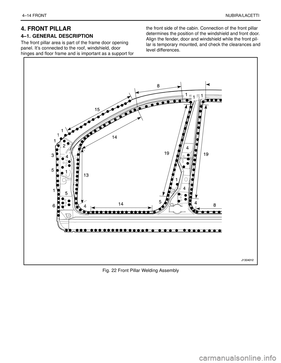
4–1. GENERAL DESCRIPTION
The front pillar area is part of the frame door opening
panel. It’s connected to the roof, windshield, door
hinges and floor frame and is important as a support forthe front side of the cabin. Connection of the front pillar
determines the position of the windshield and front door.
Align the fender, door and windshield while the front pil-
lar is temporary mounted, and check the clearances and
level differences.
Fig. 22 Front Pillar Welding Assembly