2004 DAEWOO NUBIRA power steering
[x] Cancel search: power steeringPage 227 of 2643
ENGINE ELECTRICAL 1E – 13
DAEWOO V–121 BL4
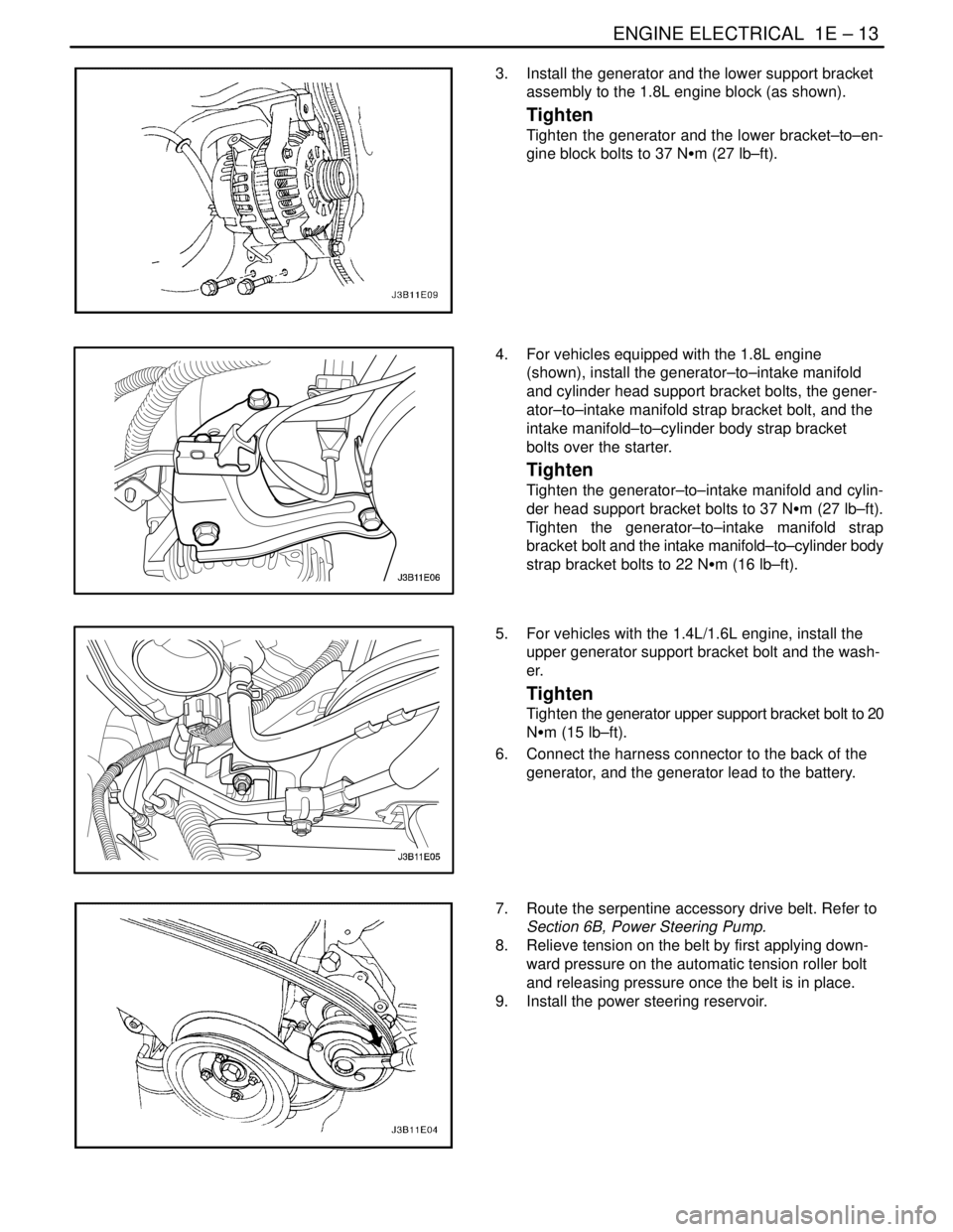
3. Install the generator and the lower support bracket
assembly to the 1.8L engine block (as shown).
Tighten
Tighten the generator and the lower bracket–to–en-
gine block bolts to 37 NSm (27 lb–ft).
4. For vehicles equipped with the 1.8L engine
(shown), install the generator–to–intake manifold
and cylinder head support bracket bolts, the gener-
ator–to–intake manifold strap bracket bolt, and the
intake manifold–to–cylinder body strap bracket
bolts over the starter.
Tighten
Tighten the generator–to–intake manifold and cylin-
der head support bracket bolts to 37 NSm (27 lb–ft).
Tighten the generator–to–intake manifold strap
bracket bolt and the intake manifold–to–cylinder body
strap bracket bolts to 22 NSm (16 lb–ft).
5. For vehicles with the 1.4L/1.6L engine, install the
upper generator support bracket bolt and the wash-
er.
Tighten
Tighten the generator upper support bracket bolt to 20
NSm (15 lb–ft).
6. Connect the harness connector to the back of the
generator, and the generator lead to the battery.
7. Route the serpentine accessory drive belt. Refer to
Section 6B, Power Steering Pump.
8. Relieve tension on the belt by first applying down-
ward pressure on the automatic tension roller bolt
and releasing pressure once the belt is in place.
9. Install the power steering reservoir.
Page 862 of 2643

1F – 616IENGINE CONTROLS
DAEWOO V–121 BL4
3. Remove the crankshaft position sensor (CKP) bolt.
4. Remove the CKP sensor.
Installation Procedure
1. Install the CKP sensor with the bolt.
Tighten
Tighten the crankshaft position sensor (CKP) bolt to
6.5 NSm (57 lb–in).
2. Connect the CKP sensor electrical connector.
3. Connect the negative battery cable.
CRANKSHAFT POSITION (CKP)
SENSOR (1.8L DOHC)
Removal Procedure
1. Disconnect the negative battery cable.
2. Remove the power steering pump, if equipped. Re-
fer to Section 6B, Power Steering Pump.
3. Remove the A/C compressor. Refer to Section 7D,
Automatic Temperature Control Heating, Ventilation
and Air Conditioning System.
4. Remove the rear A/C compressor mounting bracket
bolts and the rear A/C compressor mounting brack-
et.
Page 863 of 2643

ENGINE CONTROLS 1F – 617
DAEWOO V–121 BL4
5. Remove the accessory mounting bracket by remov-
ing the bolts.
6. Disconnect the crankshaft position (CKP) sensor
connector.
7. Remove the CKP sensor retaining bolt.
8. Gently rotate and remove the CKP sensor from the
engine block.
Installation Procedure
1. Insert the CKP sensor into the engine block.
2. Install the CKP sensor retaining bolt.
Tighten
Tighten the crankshaft position sensor retaining bolt
to 8 NSm (71 lb–in).
3. Connect the CKP sensor connector.
4. Install the accessory mounting bracket with the
bolts.
Tighten
Tighten the accessory mounting bracket bolts to 27
NSm (37 lb–ft).
5. Install the rear A/C mounting bracket.
Tighten
Tighten the rear A/C mounting bracket bolts to 35
NSm (26 lb–ft).
6. Install the A/C compressor. Refer to Section 7D,
Automatic Temperature Control Heating, Ventilation
and Air Conditioning System.
7. Install the power steering pump. Refer to Section
6B, Power Steering Pump.
8. Connect the negative battery cable.
Page 902 of 2643

SECTION : 2A
SUSPENSION DIAGNOSIS
TABLE OF CONTENTS
DIAGNOSIS2A–1 . . . . . . . . . . . . . . . . . . . . . . . . . . . . . . . .
General Diagnosis 2A–1. . . . . . . . . . . . . . . . . . . . . . . . . Torque Steer 2A–5. . . . . . . . . . . . . . . . . . . . . . . . . . . . . .
Tapered Roller Bearing 2A–6. . . . . . . . . . . . . . . . . . . . .
DIAGNOSIS
GENERAL DIAGNOSIS
Problems in the steering, the suspension, the tires, and
the wheels involve several systems. Consider all systems
when diagnosing a complaint. Some problems, such as
abnormal or excessive tire wear and scuffed tires, may be
the result of hard driving. Always road test the vehicle first.If possible, do this road test with the customer.
Proceed with the following preliminary checks. Correct
any substandard conditions.
Preliminary Checks
ChecksAction
Inspect the tires for improper pressure and uneven wear.Inflate the tires to the proper pressure.
Inspect the joint from the steering column to the steering
gear for loose connections or wear.Tighten the intermediate shaft pinch bolts. Replace the in-
termediate shaft as needed.
Inspect the front and the rear suspension, the steering
gear, and the linkage for loose or damaged parts.Tighten the front and the rear suspension. Tighten the
steering gear mounting bracket bolts. Tighten the coupling
flange pinch bolts. Replace the front and the rear suspen-
sion as needed. Replace the steering gear as needed. Re-
place the intermediate shaft as needed.
Inspect for out–of–round tires.Perform a free runout test. Match–mount the tires.
Inspect for out–of–balance tires, bent wheels, and worn or
loose wheel bearings.Balance the wheels. Replace the wheels. Replace the
wheel bearings.
Check the power steering pump serpentine belt tension.Tighten the power steering pump serpentine belt.
Inspect the power steering system for leaks. Check the
power steering fluid level.Repair any leaks. Perform a power steering gear test. Add
power steering fluid.
Car Lead/Pull
ChecksAction
Inspect for mismatched or uneven tires.Replace the tires.
Inspect for a broken or a sagging spring.Replace the spring.
Inspect for a radial tire lateral force.Check the wheel alignment. Switch the wheels. Replace
the tires as needed.
Check the front–wheel alignment.Align the front wheels.
Inspect for an off–center steering gear.Reseat the pinion valve assembly. Replace the pinion
valve assembly as needed.
Inspect for front–brake dragging.Adjust the front brakes.
Page 903 of 2643

2A – 2ISUSPENSION DIAGNOSIS
DAEWOO V–121 BL4
Abnormal or Excessive Tire Wear
ChecksAction
Check the front–wheel and the rear–wheel alignment.Align the front and the rear wheels.
Inspect for excessive toe on the front and the rear wheels.Adjust the toe on the front and the rear wheels.
Inspect for a broken or a sagging spring.Replace the spring.
Inspect for out–of–balance tires.Balance the tires.
Inspect for worn strut dampeners.Replace the strut dampeners.
Check for a failure to rotate tires.Rotate the tires. Replace the tires as needed.
Check for an overloaded vehicle.Maintain the proper load weight.
Inspect for low tire inflation.Inflate the tires to the proper pressure.
Scuffed Tires
ChecksAction
Inspect for incorrect toe on the front and the rear wheels.Adjust the toe on the front and the rear wheels.
Inspect for a twisted or a bent suspension arm.Replace the suspension arm.
Wheel Tramp
ChecksAction
Inspect for an out–of–balance tire or wheel.Balance the tire or the wheel.
Inspect for improper strut dampener action.Replace the strut dampeners.
Shimmy, Shake, or Vibration
ChecksAction
Inspect for an out–of–balance tire or wheel.Balance the tire or the wheel.
Inspect for excessive wheel hub runout.Measure the hub flange runout. Replace the hub as need-
ed.
Inspect for excessive brake drum or brake rotor imbal-
ance.Adjust the brakes. Replace the brake rotor or the brake
drum as needed.
Inspect for worn tie rod ends.Replace the outer tie rods.
Inspect for wheel trim imbalance.Balance the wheel.
Inspect for a worn lower ball joint.Replace the lower ball joint.
Inspect for excessive wheel runout.Measure the wheel runout. Replace the wheel as needed.
Inspect for excessive loaded radial runout on the tire and
wheel assembly.Match–mount the tire and wheel assembly.
Hard Steering
ChecksAction
Check the steering gear preload adjustment.Perform a rack bearing preload adjustment.
Check the hydraulic system. Test the power steering sys-
tem pressure with a gauge.Replace the seals and the hoses as needed.
Inspect for binding or catching in the steering gear.Lubricate the steering gear. Repair or replace the steering
gear as needed.
Inspect for a loose steering gear mounting.Tighten the steering gear mounting bracket nuts.
Page 906 of 2643

SUSPENSION DIAGNOSIS 2A – 5
DAEWOO V–121 BL4
Steering Wheel Kickback
ChecksAction
Inspect for air in the power steering system.Purge the power steering system of air.
Inspect for a loose steering gear mounting.Tighten the steering gear mounting bracket nuts.
Inspect the joint from the column to the steering gear for
loose connections or wear.Tighten the intermediate shaft pinch bolts. Replace the in-
termediate shaft as needed.
Inspect for loose tie rod ends.Tighten the tie rod ends. Replace the outer tie rods as
needed.
Inspect for loose or worn wheel bearings.Tighten the drive axle nut. Replace the wheel bearings as
needed.
Steering Wheel Surges or Jerks
ChecksAction
Check the hydraulic system. Test the power steering sys-
tem pressure with a gauge.Replace the seals and the hoses as needed.
Inspect for a sluggish steering gear valve.Clean the pinion valve assembly. Replace the pinion valve
assembly as needed.
Inspect for a loose power steering pump serpentine belt.Adjust the power steering pump serpentine belt.
Cupped Tires
ChecksAction
Check the front–wheel and the rear–wheel alignment.Align the front and the rear wheels.
Inspect for worn strut dampeners.Replace the strut dampeners.
Inspect for worn or loose wheel bearings.Tighten the drive axle nut. Replace the wheel bearings as
needed.
Inspect for excessive tire or wheel runout.Match–mount the tires. Replace the tires as needed. Re-
place the wheels as needed.
Inspect for a worn ball joint.Replace the ball joint.
Check the steering gear preload adjustment.Perform a rack bearing preload adjustment.
TORQUE STEER
A degree of torque steer to the right may be experienced
during the use of heavy throttle on some front–wheel drive
cars with drive axles of unequal length. This torque steer
to the right results from the right drive axle being longer
than the left drive axle, which creates a difference in the
drive axle angle. Cars with intermediate shaft assemblies
have axles of almost equal length.
A difference in the drive axle lengths results in more torque
toe–in in the left front wheel. You will notice the torque toe–
in when the vehicle accelerates from a standing start or at
lower speeds.
Inspection Procedure
1. Place a small piece of tape at the top center of the
steering wheel.2. Note the inches of steering wheel deflection re-
quired to keep the vehicle straight during heavy ac-
celeration.
3. Compare this finding with similar cars.
Factors that may cause torque steer to be more apparent
on a particular vehicle include:
S Variations in the tire and wheel assemblies. This
has the most significant effect on torque steer. A
slightly smaller diameter on the right front tire will
increase a right torque lead.
S Large differences in the right and the left front tire
pressure.
S Looseness in the control arm bushings, the tie rod
assemblies, or the steering gear mounting. This
looseness permits a front wheel to pull forward and
toe–in under a torque greater than the wheel on the
opposite side. A loose suspension component may
result in an opposite lead upon deceleration.
Page 915 of 2643

2B – 8IWHEEL ALIGNMENT
DAEWOO V–121 BL4
PRELIMINARY INSPECTION
ChecksAction
Check the tires for proper inflation pressures and normal
tread wear.Inflate the tires to the proper tire pressure. Replace the
tires as needed.
Check the wheel bearings for looseness.Tighten the axle nut to the proper specification. Replace
the strut wheel bearing as needed.
Check for loose ball joints and tie rod ends.Tighten the ball joints and the tie rods.
Check the runout of the wheels and the tires.Measure and correct the tire runout.
Check the vehicle trim heights.Correct the trim heights. Make the correction before ad-
justing the toe.
Check for loose rack and pinion mounting.Tighten the mounting brackets for the rack and pinion as-
sembly.
Check for improperly operating struts.Replace the strut assembly.
Check for loose control arms.Tighten the control arm attachment bolts. Replace the con-
trol arm bushings as needed.
FRONT TOE ADJUSTMENT
1. Disconnect the outer tie rods from the knuckle as-
semblies. Refer to Section 6C, Power Steering
Gear.
2. Turn the right and the left outer tie rods and the ad-
juster nuts to align the toe to 0.0 ± 0.10 degree.
3. Reconnect the outer tie rods to the knuckle assem-
blies. Refer to Section 6C, Power Steering Gear.
Notice : In this adjustment, the right and the left tie rods
must be equal in length, or the tires will wear unevenly.FRONT CAMBER AND CASTER
CHECK
The front camber and caster are not adjustable. Refer to
”Wheel Alignment Specifications” in this section. Jounce
the bumper three times before measuring the camber or
the caster in order to prevent an incorrect reading. If the
front camber or caster measurements deviate from the
specifications, locate and replace or repair any damaged,
loose, bent, dented, or worn suspension part. If the prob-
lem is body related, repair the body.
REAR CAMBER CHECK
The rear camber is not adjustable. Refer to ”Wheel Align-
ment Specifications” in this section. If the rear camber
deviates from the specification, locate the cause and cor-
rect it. If damaged, loose, bent, dented, or worn suspen-
sion parts are found, they should be repaired or replaced.
If the problem is body related, repair the body.
Page 928 of 2643

FRONT SUSPENSION 2C – 11
DAEWOO V–121 BL4
4. Remove the brake caliper from the rotor. Support
the caliper so it does not hang from the hydraulic
brake hose. Refer to Section 4D, Front Disc
Brakes.
5. Remove the outer tie rod from the knuckle assem-
bly. Refer to Section 6C, Power Steering Gear.
6. On vehicles equipped with the antilock braking sys-
tem (ABS), disconnect the ABS speed sensor elec-
trical connection from the knuckle.
7. Remove the ball joint pinch bolt and the nut.
8. Separate the knuckle from the ball joint using the
ball joint remover KM–507–B.
9. Remove the nuts from the bolts that connect the
knuckle assembly to the strut assembly.