Page 2364 of 2643
9H – 8ISEATS
DAEWOO V–121 BL4
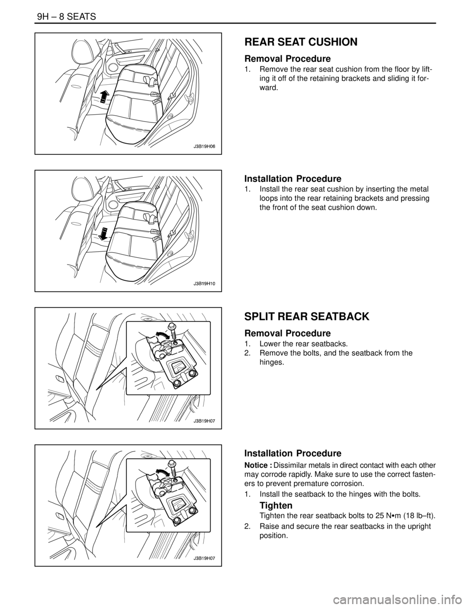
REAR SEAT CUSHION
Removal Procedure
1. Remove the rear seat cushion from the floor by lift-
ing it off of the retaining brackets and sliding it for-
ward.
Installation Procedure
1. Install the rear seat cushion by inserting the metal
loops into the rear retaining brackets and pressing
the front of the seat cushion down.
SPLIT REAR SEATBACK
Removal Procedure
1. Lower the rear seatbacks.
2. Remove the bolts, and the seatback from the
hinges.
Installation Procedure
Notice : Dissimilar metals in direct contact with each other
may corrode rapidly. Make sure to use the correct fasten-
ers to prevent premature corrosion.
1. Install the seatback to the hinges with the bolts.
Tighten
Tighten the rear seatback bolts to 25 NSm (18 lb–ft).
2. Raise and secure the rear seatbacks in the upright
position.
Page 2365 of 2643
SEATS 9H – 9
DAEWOO V–121 BL4
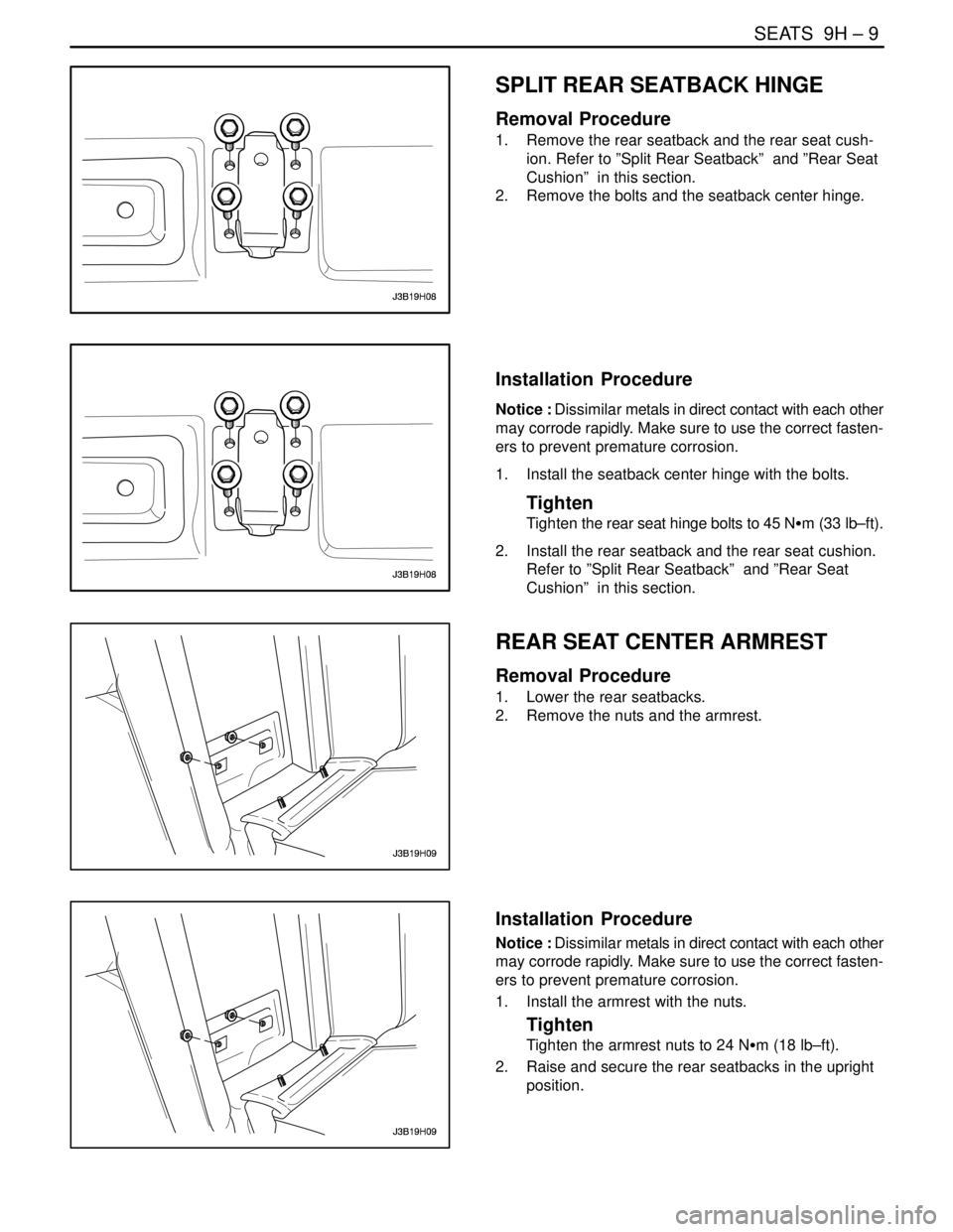
SPLIT REAR SEATBACK HINGE
Removal Procedure
1. Remove the rear seatback and the rear seat cush-
ion. Refer to ”Split Rear Seatback” and ”Rear Seat
Cushion” in this section.
2. Remove the bolts and the seatback center hinge.
Installation Procedure
Notice : Dissimilar metals in direct contact with each other
may corrode rapidly. Make sure to use the correct fasten-
ers to prevent premature corrosion.
1. Install the seatback center hinge with the bolts.
Tighten
Tighten the rear seat hinge bolts to 45 NSm (33 lb–ft).
2. Install the rear seatback and the rear seat cushion.
Refer to ”Split Rear Seatback” and ”Rear Seat
Cushion” in this section.
REAR SEAT CENTER ARMREST
Removal Procedure
1. Lower the rear seatbacks.
2. Remove the nuts and the armrest.
Installation Procedure
Notice : Dissimilar metals in direct contact with each other
may corrode rapidly. Make sure to use the correct fasten-
ers to prevent premature corrosion.
1. Install the armrest with the nuts.
Tighten
Tighten the armrest nuts to 24 NSm (18 lb–ft).
2. Raise and secure the rear seatbacks in the upright
position.
Page 2377 of 2643

SECTION : 9K
SQUEAKS AND RATTLES
TABLE OF CONTENTS
DIAGNOSIS9K–1 . . . . . . . . . . . . . . . . . . . . . . . . . . . . . . . .
Squeak and Rattle Diagnosis 9K–1. . . . . . . . . . . . . . . .
MAINTENANCE AND REPAIR9K–3 . . . . . . . . . . . . . . . ON–VEHICLE SERVICE 9K–3. . . . . . . . . . . . . . . . . . . . .
Squeak and Rattle Repair 9K–3. . . . . . . . . . . . . . . . . . .
DIAGNOSIS
SQUEAK AND RATTLE DIAGNOSIS
Rattle Coming From the Side Rail
ChecksAction
Check the brake lines.S Tap lightly on the brake lines and listen for a rattle.
S Install plastic tie straps to secure the brake lines
tightly together.
Rattle Under Vehicle at Higher RPM
ChecksAction
Check for heat shield contact with the underbody.S Raise the vehicle and perform a visual inspection.
S Bend the heat shield slightly to gain clearance from
the underbody.
Squeak From the Front of the Vehicle in Cold Weather
ChecksAction
Check the front stabilizer shaft insulators.S While the vehicle is cold, perform a test drive and
achieve full front suspension travel by driving through
a dip in the road.
S Remove the insulators and wrap teflon tape around
the stabilizer shaft. Reinstall the insulators over the
tape.
Thump From Rear of Vehicle on Bumps
ChecksAction
Check for a properly secured spare tire in the rear
compartment.S Open the rear compartment and perform a visual
inspection of the spare tire and the tools.
S Tightly secure the spare tire and all tools.
S Perform a road test to verify that the noise is elimi-
nated.
Page 2379 of 2643
SQUEAKS AND RATTLES 9K – 3
DAEWOO V–121 BL4
MAINTENANCE AND REPAIR
ON–VEHICLE SERVICE
SQUEAK AND RATTLE REPAIR
Squeaks and rattles are caused by the unwanted move-
ment between parts of a vehicle. There are three means
to prevent squeaks or rattles.
S Attach the parts securely so that there is no relative
motion during the operation of the vehicle.
S Separate the parts so that there is no contact dur-
ing operation.
S Insulate the parts so that no squeaks or rattles oc-
cur with the movement of the parts. Low uniform
friction surfaces can be used to eliminate ”stick–
slip” motion.
Page 2385 of 2643

9L – 6IGLASS AND MIRRORS
DAEWOO V–121 BL4
StepNo Yes Value(s) Action
81. Turn the ignition OFF.
2. Disconnect the outside rearview mirror electri-
cal connector.
3. Use an ohmmeter to measure the resistance
between terminal 8 (BLK) of the outside rear-
view mirror connector and ground.
Does the ohmmeter indicate the specified value?� 0 ΩGo to Step 10 Go to Step 9
9Repair the open ground circuit for the outside rear-
view mirror.
Is the repair complete?–System OK–
10Replace the defective outside rearview mirror.
Is the repair complete?–System OK–
ELECTRIC CONTROL OUTSIDE REARVIEW MIRRORS
Electric Control Outside Rearview Mirrors Do Not Adjust
StepActionValue(s)YesNo
1Check fuse F8.
Is fuse F8 blown?–Go to Step 2 Go to Step 3
21. Check for a short circuit and repair it, if neces-
sary.
2. Replace fuse F8.
Is the repair complete?–System OK–
31. Turn the ignition ON.
2. Check the voltage at fuse F8.
Is the voltage at F8 equal to the specified value?11–14 vGo to Step 5 Go to Step 4
4Repair the open power supply circuit for fuse F8.
Is the repair complete?–System OK–
5Check the electric control outside rearview mirrors.
Are both electric control outside rearview mirrors in-
operative?–Go to Step 6 Go to Step 13
61. Remove the retaining screw for the electric
control outside rearview mirror and power win-
dow switch assembly.
2. Lift the switch assembly so that the connectors
on the underside are visible.
Is the connector secured to the electric control out-
side rearview mirror switch?–Go to Step 8 Go to Step 7
7Connect the connector to the electric control outside
rearview mirror switch.
Is the repair complete?–System OK–
8Use an ohmmeter to check the continuity between
terminal 6 (BLK) of the electric control outside rear-
view mirror switch connector and ground.
Does the ohmmeter indicate the specified value?� 0 ΩGo to Step 10 Go to Step 9
9Repair the open ground circuit for the electric control
outside rearview mirror switch.
Is the repair complete?–System OK–
Page 2394 of 2643
GLASS AND MIRRORS 9L – 15
DAEWOO V–121 BL4
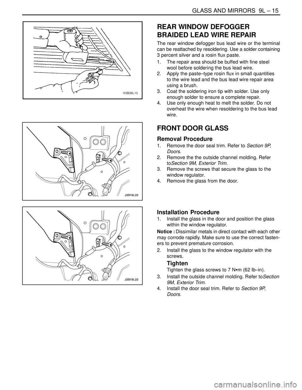
REAR WINDOW DEFOGGER
BRAIDED LEAD WIRE REPAIR
The rear window defogger bus lead wire or the terminal
can be reattached by resoldering. Use a solder containing
3 percent silver and a rosin flux paste.
1. The repair area should be buffed with fine steel
wool before soldering the bus lead wire.
2. Apply the paste–type rosin flux in small quantities
to the wire lead and the bus lead wire repair area
using a brush.
3. Coat the soldering iron tip with solder. Use only
enough solder to ensure a complete repair.
4. Use only enough heat to melt the solder. Do not
overheat the wire when resoldering to the bus lead
wire.
FRONT DOOR GLASS
Removal Procedure
1. Remove the door seal trim. Refer to Section 9P,
Doors.
2. Remove the the outside channel molding. Refer
toSection 9M, Exterior Trim.
3. Remove the screws that secure the glass to the
window regulator.
4. Remove the glass from the door.
Installation Procedure
1. Install the glass in the door and position the glass
within the window regulator.
Notice : Dissimilar metals in direct contact with each other
may corrode rapidly. Make sure to use the correct fasten-
ers to prevent premature corrosion.
2. Install the glass to the window regulator with the
screws.
Tighten
Tighten the glass screws to 7 NSm (62 lb–in).
3. Install the outside channel molding. Refer toSection
9M, Exterior Trim.
4. Install the door seal trim. Refer to Section 9P,
Doors.
Page 2395 of 2643
9L – 16IGLASS AND MIRRORS
DAEWOO V–121 BL4
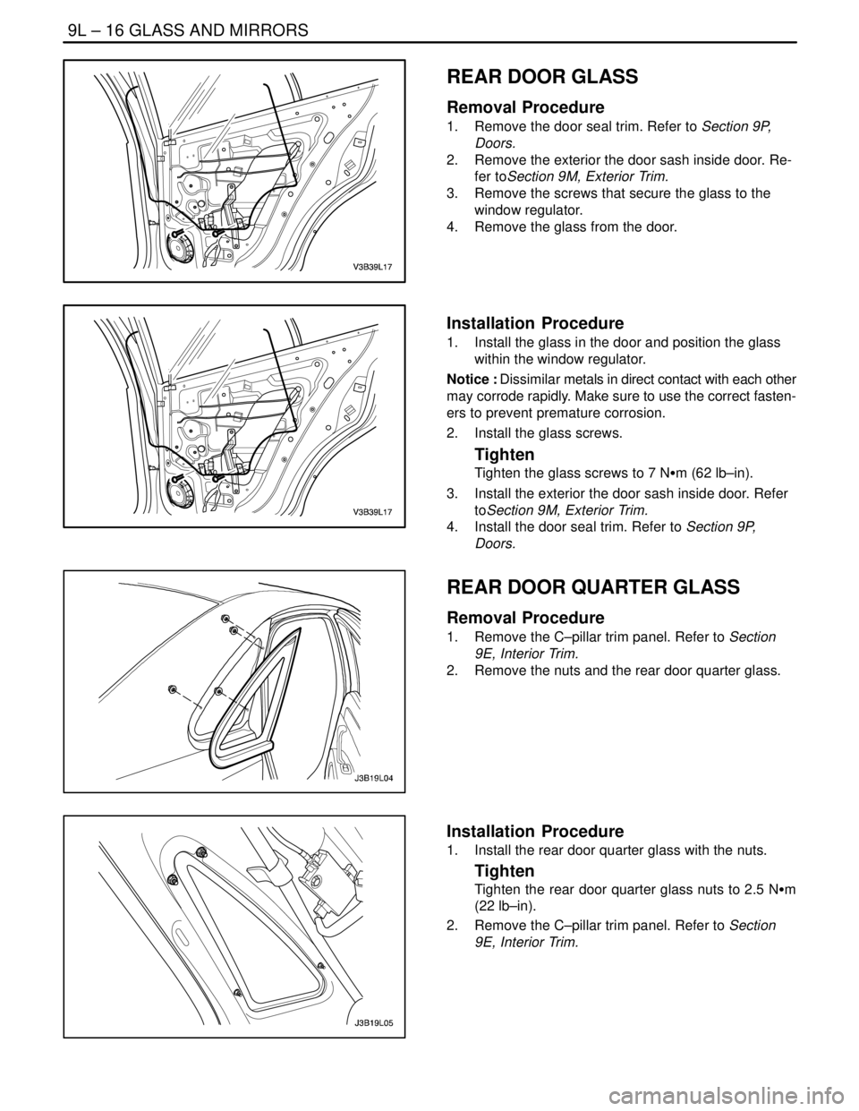
REAR DOOR GLASS
Removal Procedure
1. Remove the door seal trim. Refer to Section 9P,
Doors.
2. Remove the exterior the door sash inside door. Re-
fer toSection 9M, Exterior Trim.
3. Remove the screws that secure the glass to the
window regulator.
4. Remove the glass from the door.
Installation Procedure
1. Install the glass in the door and position the glass
within the window regulator.
Notice : Dissimilar metals in direct contact with each other
may corrode rapidly. Make sure to use the correct fasten-
ers to prevent premature corrosion.
2. Install the glass screws.
Tighten
Tighten the glass screws to 7 NSm (62 lb–in).
3. Install the exterior the door sash inside door. Refer
toSection 9M, Exterior Trim.
4. Install the door seal trim. Refer to Section 9P,
Doors.
REAR DOOR QUARTER GLASS
Removal Procedure
1. Remove the C–pillar trim panel. Refer to Section
9E, Interior Trim.
2. Remove the nuts and the rear door quarter glass.
Installation Procedure
1. Install the rear door quarter glass with the nuts.
Tighten
Tighten the rear door quarter glass nuts to 2.5 NSm
(22 lb–in).
2. Remove the C–pillar trim panel. Refer to Section
9E, Interior Trim.
Page 2396 of 2643
GLASS AND MIRRORS 9L – 17
DAEWOO V–121 BL4
INSIDE REARVIEW MIRROR
The inside rearview mirror is attached to a support which
is secured to the windshield glass. The support is installed
by the glass supplier using a plastic–polyvinyl butyl adhe-
sive.
Service replacement windshield glass has the mirror sup-
port bonded to the glass assembly. In order to install a de-
tached mirror support or to install a new part, the following
items will be needed:
S Loctite® Minute–Bond Adhesive.
S Original or replacement mirror support.
S Wax marking pencil or crayon.
S Rubbing alcohol.
S Clean paper towel.
S Fine grit sandpaper (grit #320 or #360).
S 2 mm allen wrench.
Installation Procedure
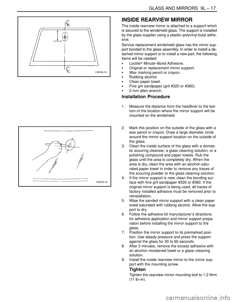
1. Measure the distance from the headliner to the bot-
tom of the location where the mirror support will be
mounted on the windshield.
2. Mark this position on the outside of the glass with a
wax pencil or crayon. Draw a large diameter circle
around the mirror support location on the outside of
the glass.
3. Clean the inside surface of the glass with a domes-
tic scouring cleanser, a glass cleaning solution, or a
polishing compound and paper towels. Rub the
glass until the area is completely dry. When the
area is dry, clean the area with an alcohol–satu-
rated paper towel in order to remove any traces of
the scouring powder or the glass cleaning solution.
4. If the mirror support is new, clean the bonding sur-
face with fine grit sandpaper #320 or #360. If the
original mirror support is being used, all traces of
factory installed adhesive must be removed prior to
reinstallation.
5. Wipe the sanded mirror support with a clean paper
towel saturated with rubbing alcohol. Allow the sup-
port to dry.
6. Follow the adhesive kit manufacturer’s directions
for adhesive application and mirror support prepa-
ration before installing the mirror support to the
glass.
7. Position the mirror support to its premarked posi-
tion. Use steady pressure and press the support
against the glass for 30 to 60 seconds.
8. After 5 minutes, remove the excess adhesive with
an alcohol–moistened towel or a glass–cleaning
solution.
9. Install the inside rearview mirror to the mirror sup-
port with the mounting screw.
Tighten
Tighten the rearview mirror mounting bolt to 1.2 NSm
(11 lb–in).