Page 1681 of 2643

AISIN AUTOMATIC TRANSAXLE 5A2 – 91
DAEWOO V–121 BL4
DIAGNOSTIC TROUBLE CODE (DTC) P1791
THROTTLE POSITION SIGNAL ERROR
Conditions for Setting the DTC
S TCM detects that malfunction of throttle position
signal for 2 seconds continuously.
S No DTC U2105
Action Taken When the DTC Sets
S TCM will request the illumination of MIL and store
DTC when TCM detects a failure on the first ignition
cycle.
S TCM judges the throttle opening is 0% for shift
point control.
S TCM judges the throttle opening is 100% for line
pressure control.
S No lock–up
S No 4th gear
S No self–learning controlS No timing solenoid control for N–D
Conditions for Clearing the DTC
S The TCM turns off the MIL when no further failures
detected for three consecutive ignition cycles.
S The scan tool can clear the DTC from the TCM his-
tory.
S The TCM clears the DTC from the TCM history
memory after forty consecutive warm up cycles
without fault.
Cause of Failure
S Wiring harness or connector between ECM and
TCM
S ECM
S TCM
Page 1683 of 2643
AISIN AUTOMATIC TRANSAXLE 5A2 – 93
DAEWOO V–121 BL4
DIAGNOSTIC TROUBLE CODE (DTC) P1792
ENGINE COOLANT TEMPERATURE (ECT) SIGNAL
ERROR
Conditions for Setting the DTC
S TCM detects malfunction of Engine Coolant Tem-
perature (ECT) signal for 2 seconds continuously.
S No DTC U2105
Action Taken When the DTC Sets
S TCM will not request the illumination of MIL, but will
store DTC when TCM detects a failure on the first
ignition cycle.
S TCM judges the engine coolant temperature 90 de-
grees when lapse 15 minutes from ignition ON.Conditions for Clearing the DTC
S The scan tool can clear the DTC from the TCM his-
tory.
S The TCM clears the DTC from the TCM history
memory after forty consecutive warm up cycles
without fault.
Cause of Failure
S Wiring harness or connector between ECM and
TCM
S ECM
S TCM
Page 1685 of 2643

AISIN AUTOMATIC TRANSAXLE 5A2 – 95
DAEWOO V–121 BL4
DIAGNOSTIC TROUBLE CODE (DTC) U2105
CAN ERROR
Conditions for Setting the DTC
S TCM detects that the BUS OFF signal. This detec-
tion is continued for 0.2 seconds.
S TCM detects that nothing of ECM signal on CAN
BUS for 0.2 seconds. This detection is continued
for 2.0 seconds.
Action Taken When the DTC Sets
S TCM will request the illumination of MIL and store
DTC when TCM detects a failure on the first ignition
cycle.
S TCM judges the throttle opening is 0% for shift
point and lock–up point control.
S TCM judges the throttle opening is 100% for line
pressure control.
S No lock–upS No self–learning control
S No 4th gear
S TCM judges the engine revolution is 0 rpm.
Conditions for Clearing the DTC
S The TCM turns off the MIL when no further failures
detected for three consecutive ignition cycles.
S The scan tool can clear the DTC from the TCM his-
tory.
S TCM detects the BUS normal signal for 2 seconds
continuously.
Cause of Failure
S Wiring harness or connector between ECM and
TCM
S ECM
S TCM
Page 1703 of 2643
AISIN AUTOMATIC TRANSAXLE 5A2 – 113
DAEWOO V–121 BL4
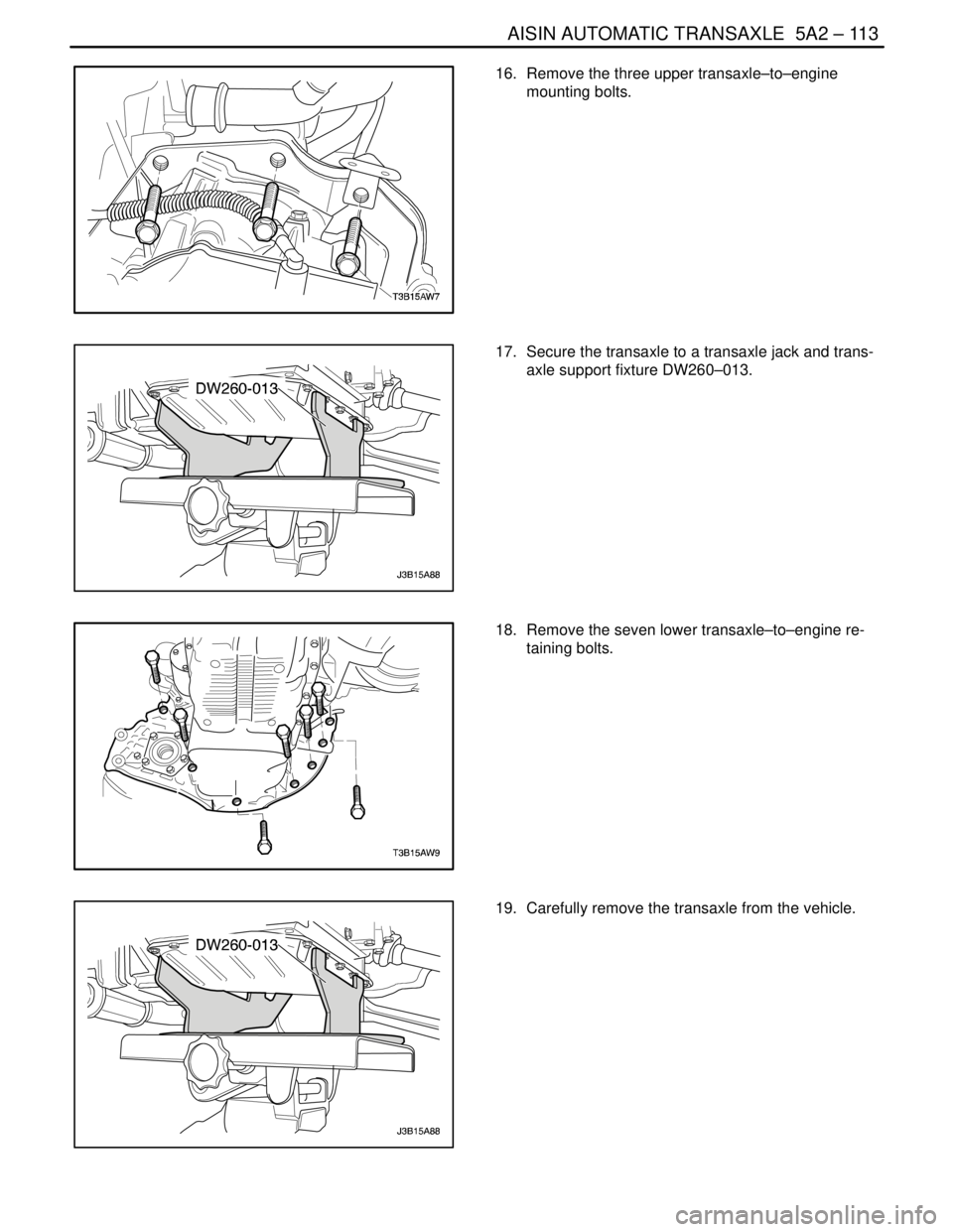
16. Remove the three upper transaxle–to–engine
mounting bolts.
17. Secure the transaxle to a transaxle jack and trans-
axle support fixture DW260–013.
18. Remove the seven lower transaxle–to–engine re-
taining bolts.
19. Carefully remove the transaxle from the vehicle.
Page 1704 of 2643
5A2 – 114IAISIN AUTOMATIC TRANSAXLE
DAEWOO V–121 BL4
Installation Procedure
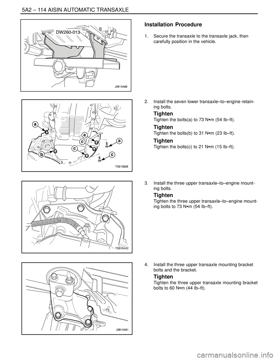
1. Secure the transaxle to the transaxle jack, then
carefully position in the vehicle.
2. Install the seven lower transaxle–to–engine retain-
ing bolts.
Tighten
Tighten the bolts(a) to 73 NSm (54 Ib–ft).
Tighten
Tighten the bolts(b) to 31 NSm (23 Ib–ft).
Tighten
Tighten the bolts(c) to 21 NSm (15 Ib–ft).
3. Install the three upper transaxle–to–engine mount-
ing bolts.
Tighten
Tighten the three upper transaxle–to–engine mount-
ing bolts to 73 NSm (54 Ib–ft).
4. Install the three upper transaxle mounting bracket
bolts and the bracket.
Tighten
Tighten the three upper transaxle mounting bracket
bolts to 60 NSm (44 Ib–ft).
Page 1737 of 2643
AISIN AUTOMATIC TRANSAXLE 5A2 – 147
DAEWOO V–121 BL4
45. Turn the spacer and lever shaft to align the small
hole for locating the staking position in the spacer
with the staking position mark on the lever shaft.
46. Using a pin punch, stake the spacer through the
small hole.
47. Check that the spacer does not turn.
48. Install the manual detent spring with the bolt.
Tighten
Tighten the bolts to 9.8 NSm (87 lb–in).
49. Install the parking lock shaft, torsion spring and
parking lock pawl.
Notice : Check that the edge of torsion spring fits into the
groove securely.
Page 1839 of 2643
FIVE–SPEED MANUAL TRANSAXLE 5B – 15
DAEWOO V–121 BL4
MAINTENANCE AND REPAIR
ON–VEHICLE SERVICE
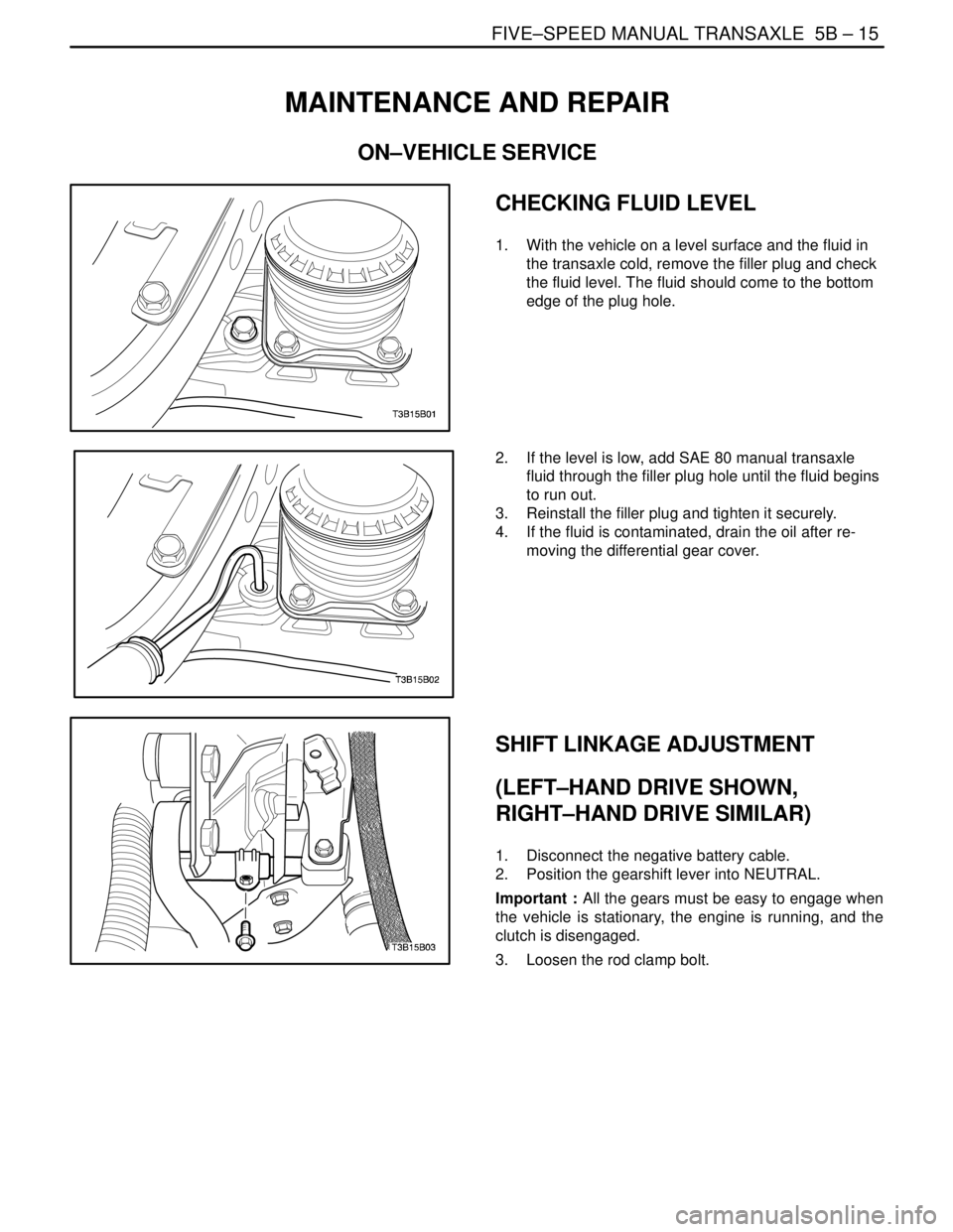
CHECKING FLUID LEVEL
1. With the vehicle on a level surface and the fluid in
the transaxle cold, remove the filler plug and check
the fluid level. The fluid should come to the bottom
edge of the plug hole.
2. If the level is low, add SAE 80 manual transaxle
fluid through the filler plug hole until the fluid begins
to run out.
3. Reinstall the filler plug and tighten it securely.
4. If the fluid is contaminated, drain the oil after re-
moving the differential gear cover.
SHIFT LINKAGE ADJUSTMENT
(LEFT–HAND DRIVE SHOWN,
RIGHT–HAND DRIVE SIMILAR)
1. Disconnect the negative battery cable.
2. Position the gearshift lever into NEUTRAL.
Important : All the gears must be easy to engage when
the vehicle is stationary, the engine is running, and the
clutch is disengaged.
3. Loosen the rod clamp bolt.
Page 1841 of 2643
FIVE–SPEED MANUAL TRANSAXLE 5B – 17
DAEWOO V–121 BL4
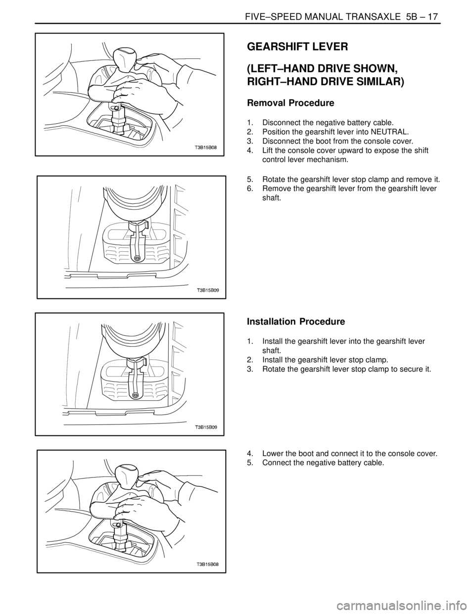
GEARSHIFT LEVER
(LEFT–HAND DRIVE SHOWN,
RIGHT–HAND DRIVE SIMILAR)
Removal Procedure
1. Disconnect the negative battery cable.
2. Position the gearshift lever into NEUTRAL.
3. Disconnect the boot from the console cover.
4. Lift the console cover upward to expose the shift
control lever mechanism.
5. Rotate the gearshift lever stop clamp and remove it.
6. Remove the gearshift lever from the gearshift lever
shaft.
Installation Procedure
1. Install the gearshift lever into the gearshift lever
shaft.
2. Install the gearshift lever stop clamp.
3. Rotate the gearshift lever stop clamp to secure it.
4. Lower the boot and connect it to the console cover.
5. Connect the negative battery cable.