2004 DAEWOO NUBIRA clutch
[x] Cancel search: clutchPage 2016 of 2643

7B – 14IMANUAL CONTROL HEATING, VENTILATION AND AIR CONDITIONING SYSTEM
DAEWOO V–121 BL4
StepNo Yes Value(s) Action
151. Record the low– and the high–side pressures
after the A/C system has been operating for 5
minutes or more with the engine cooling fan
ON.
2. Locate the intersection of the low– and the high
side pressures. Refer to ”Low– and High–Side
Pressure Relationship Chart” in this section.
Do the low– and the high–side pressures intersect
in the white area of the chart?–System OKGo to Step 16
16Check the high– and the low–side pressures.
Do the low– and the high–side pressures intersect
in the grey area of the chart?–Go to Step 17Go to Step 20
17Feel the liquid pipe between the condenser and the
expansion valve.
Is the pipe cold?–Go to Step 18Go to Step 19
181. Examine the condenser for any restriction of
the airflow.
2. Check the cooling fans for proper operation.
3. Remove the restriction or repair the fans, as
required.
Is the pipe temperature normal now?At least 7°C
(12°F) below
ambient air
temperatureGo to Step 13–
191. Recover, evacuate, and recharge the A/C sys-
tem.
2. Check the A/C system for leaks.
Is the system free from leaks?–Go to Step 13–
20Observe the readings on the pressure gauges.
Are the A/C compressor high– and the low–side
pressures within the specified value of each other?207 kPa
(30 psi)Go to Step 21Go to Step 26
211. Run the engine at 3,000 rpm.
2. Set the A/C controls to the following positions:
S The A/C switch to the ON.
S The fresh air control switch to fresh air.
S The blower motor to 4.
S The temperature to full cold.
3. Close all of the vehicle’s windows and doors.
4. Turn the A/C switch ON and OFF every 20
seconds for 3 minutes.
Are the A/C compressor high– and the low–side
pressures within the specified value of each other?207 kPa
(30 psi)Go to Step 22Go to Step 13
22Observe the pressure rise on both gauges and the
temperatures of both the compressor suction pipe
and the discharge pipe.
Is the pressure rise on both gauges slow and the
suction pipe warm with the discharge pipe very hot?–Go to Step 25Go to Step 23
231. Turn the ignition switch to LOCK.
2. Make sure the compressor clutch is disen-
gaged.
3. Attempt to turn the clutch driver (not the
pulley).
Can you turn the clutch driver freely by hand?–Go to Step 25Go to Step 24
Page 2019 of 2643

MANUAL CONTROL HEATING, VENTILATION AND AIR CONDITIONING SYSTEM 7B – 17
DAEWOO V–121 BL4
Test ResultsRemedy Probable Cause Related Symptioms
Suction pressure ab-
normally highSuction pressure is lowered
when the condenser is
cooled by water.Excessive refrigerant in the sys-
tem.Recover, evacuate, and re-
charge the system.
High and low pressure are
equalized as soon as the
compressor is stopped and
both gauges fluctuate while
the compressor is running.Faulty gasket.Repair or replace the com-
pressor.
Faulty high–pressure valve. (V5
compressor only)
Foreign particles stuck in the
high–pressure valve. (V5 com-
pressor only)
Suction and dis-
charge pressure ab-
ll hi h
Reduced airflow through
the condenser.Clogged condenser or radiator
fins.Clean the condenser and
the radiator.
g
normally highRadiator cooling fans working im-
properly.Check the voltage and the
radiator cooling fan rpm.
Check the fan direction.
Condenser is excessively
hot.Excessive refrigerant in the sys-
tem.Recover, evacuate, and re-
charge the system.
Suction and dis-
charge pressure ab-
normally lowLow–pressure hose and
metal end areas are cooler
than the evaporator.Clogged or kinked low–pressure
hose.Repair or replace the low–
pressure hose.
Temperature around the ex-
pansion valve is low
compared to that around
the receiver–dryer.Clogged high–pressure line.Repair or replace the high–
pressure line.
Refrigerant leaksThe compressor clutch is
dirty.Leaking compressor shaft seal.Repair or replace the com-
pressor.
The compressor bolts are
dirty.Leaking around a compressor
housing bolt.Tighten the bolt(s) or re-
place the compressor.
The compressor gasket is
wet with oil.Leaking compressor gasket.Repair or replace the com-
pressor.
Page 2039 of 2643

MANUAL CONTROL HEATING, VENTILATION AND AIR CONDITIONING SYSTEM 7B – 37
DAEWOO V–121 BL4
UNIT REPAIR
COMPONENT LOCATOR
V5 COMPRESSOR
1. Rear Head Compressor
2. Control Valve O–Ring
3. Rear Head Gasket
4. Valve Plate
5. Suction Reed
6. Clutch Coil
7. Retaining Ring
8. Drive Plate Clutch
9. Pulley Bearing
10. Clutch Hub Key
11. Shaft Nut
12. Seal Retaining Ring
13. Shaft Lip Seal
14. Shaft Seal O–Ring
15. Compressor Housing16. Compressor Control Valve
17. Pulley Bearing–to–Head Retaining Ring
18. Rotor Pulley
19. Through–Bolt
20. Through–Gasket
21. Compressor Housing–to–Cylinder O–Ring
22. Shaft and Guide Pin Assembly Cylinder
23. Rear Head O–Ring
24. Thrust Washer
25. Race
26. Bearing
27. Oil Drain Plug
28. Clutch and Hub Keyway
29. Compressor Shaft
Page 2040 of 2643

7B – 38IMANUAL CONTROL HEATING, VENTILATION AND AIR CONDITIONING SYSTEM
DAEWOO V–121 BL4
V5 AIR CONDITIONING COMPRESSOR OVERHAUL
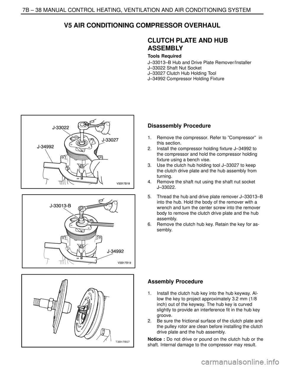
CLUTCH PLATE AND HUB
ASSEMBLY
Tools Required
J–33013–B Hub and Drive Plate Remover/Installer
J–33022 Shaft Nut Socket
J–33027 Clutch Hub Holding Tool
J–34992 Compressor Holding Fixture
Disassembly Procedure
1. Remove the compressor. Refer to ”Compressor” in
this section.
2. Install the compressor holding fixture J–34992 to
the compressor and hold the compressor holding
fixture using a bench vise.
3. Use the clutch hub holding tool J–33027 to keep
the clutch drive plate and the hub assembly from
turning.
4. Remove the shaft nut using the shaft nut socket
J–33022.
5. Thread the hub and drive plate remover J–33013–B
into the hub. Hold the body of the remover with a
wrench and turn the center screw into the remover
body to remove the clutch drive plate and the hub
assembly.
6. Remove the clutch hub key. Retain the key for as-
sembly.
Assembly Procedure
1. Install the clutch hub key into the hub keyway. Al-
low the key to project approximately 3.2 mm (1/8
inch) out of the keyway. The hub key is curved
slightly to provide an interference fit in the hub key
groove.
2. Be sure the frictional surface of the clutch plate and
the pulley rotor are clean before installing the clutch
drive plate and the hub assembly.
Notice : Do not drive or pound on the clutch hub or the
shaft. Internal damage to the compressor may result.
Page 2041 of 2643

MANUAL CONTROL HEATING, VENTILATION AND AIR CONDITIONING SYSTEM 7B – 39
DAEWOO V–121 BL4
3. Align the clutch hub key with the shaft keyway.
Place the clutch drive plate and the hub assembly
onto the compressor shaft.
4. Remove the hub and drive plate remover/installer
J–33013–B center bolt and reverse the body direc-
tion on the center bolt. The body of the hub and
drive plate remover/installer J–33013–B should be
backed off sufficiently to allow the center bolt to be
threaded onto the end of the compressor shaft.
Notice : If the center bolt is threaded fully onto the end of
the compressor shaft, or if the body of the hub and drive
plate remover/installer J–33013–B is held and the center
bolt is rotated, the key will wedge and could break the
clutch drive plate and the hub assembly.
5. Install the hub and drive plate remover/installer
J–33013–B and the bearing onto the clutch drive
plate. Thread the center bolt onto the compressor
shaft.
6. Hold the center bolt with a wrench. Tighten the hex
portion of the hub and drive plate remover/installer
J–33013–B body to press the hub onto the shaft.
Tighten the body several turns.
7. Remove the hub and drive plate remover/installer
J–33013–B and check to see that the clutch hub
key is still in place in the keyway before installing
the clutch drive plate and the hub assembly to its
final position. The air gap between frictional sur-
faces of the clutch drive plate and the clutch pulley
rotor should be 0.38 to 0.64 mm (0.015 to 0.025
inch.).
8. Remove the hub and drive plate remover/installer
J–33013–B. Check for proper positioning of the
clutch hub key. It should be even or slightly above
the clutch hub.
9. Install the shaft nut. Hold the clutch drive plate and
the hub assembly with the clutch hub holding tool
J–33027. Use the shaft nut socket J–33022 and
tighten the nut against the compressor shaft shoul-
der.
Tighten
Tighten the clutch plate and hub assembly retaining
nut to 17 NSm (13 lb–ft).
10. Spin the pulley rotor by hand to verify that the
pulley is not rubbing the clutch drive plate.
Page 2042 of 2643

7B – 40IMANUAL CONTROL HEATING, VENTILATION AND AIR CONDITIONING SYSTEM
DAEWOO V–121 BL4
11. Remove the compressor from the bench vise and
remove the J–34992 compressor holding fixture
from the compressor.
12. Install the compressor. Refer to ”Compressor” in
this section.
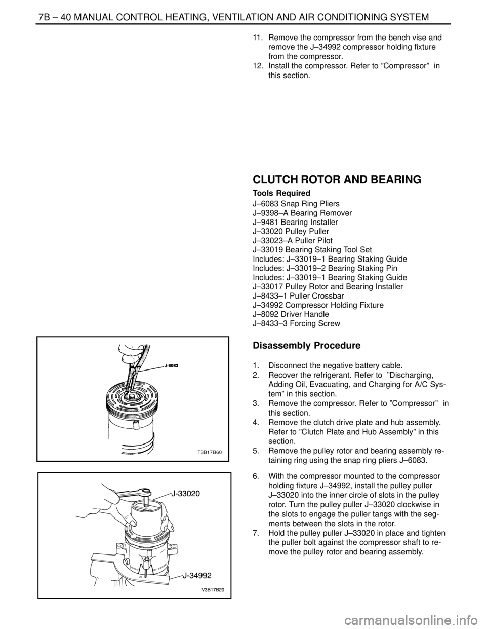
CLUTCH ROTOR AND BEARING
Tools Required
J–6083 Snap Ring Pliers
J–9398–A Bearing Remover
J–9481 Bearing Installer
J–33020 Pulley Puller
J–33023–A Puller Pilot
J–33019 Bearing Staking Tool Set
Includes: J–33019–1 Bearing Staking Guide
Includes: J–33019–2 Bearing Staking Pin
Includes: J–33019–1 Bearing Staking Guide
J–33017 Pulley Rotor and Bearing Installer
J–8433–1 Puller Crossbar
J–34992 Compressor Holding Fixture
J–8092 Driver Handle
J–8433–3 Forcing Screw
Disassembly Procedure
1. Disconnect the negative battery cable.
2. Recover the refrigerant. Refer to ”Discharging,
Adding Oil, Evacuating, and Charging for A/C Sys-
tem” in this section.
3. Remove the compressor. Refer to ”Compressor” in
this section.
4. Remove the clutch drive plate and hub assembly.
Refer to ”Clutch Plate and Hub Assembly” in this
section.
5. Remove the pulley rotor and bearing assembly re-
taining ring using the snap ring pliers J–6083.
6. With the compressor mounted to the compressor
holding fixture J–34992, install the pulley puller
J–33020 into the inner circle of slots in the pulley
rotor. Turn the pulley puller J–33020 clockwise in
the slots to engage the puller tangs with the seg-
ments between the slots in the rotor.
7. Hold the pulley puller J–33020 in place and tighten
the puller bolt against the compressor shaft to re-
move the pulley rotor and bearing assembly.
Page 2044 of 2643

7B – 42IMANUAL CONTROL HEATING, VENTILATION AND AIR CONDITIONING SYSTEM
DAEWOO V–121 BL4
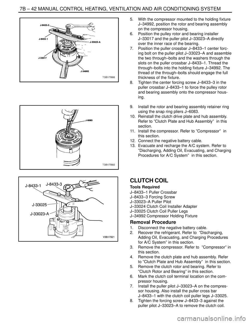
5. With the compressor mounted to the holding fixture
J–34992, position the rotor and bearing assembly
on the compressor housing.
6. Position the pulley rotor and bearing installer
J–33017 and the puller pilot J–33023–A directly
over the inner race of the bearing.
7. Position the puller crossbar J–8433–1 center forc-
ing bolt on the puller pilot J–33023–A and assemble
the two through–bolts and the washers through the
slots on the puller crossbar J–8433–1. Thread the
through–bolts into the holding fixture J–34992. The
thread of the through–bolts should engage the full
thickness of the fixture.
8. Tighten the center forcing screw J–8433–3 in the
puller crossbar J–8433–1 to force the pulley rotor
and bearing assembly onto the compressor hous-
ing.
9. Install the rotor and bearing assembly retainer ring
using the snap ring pliers J–6083.
10. Reinstall the clutch drive plate and hub assembly.
Refer to ”Clutch Plate and Hub Assembly” in this
section.
11. Install the compressor. Refer to ”Compressor” in
this section.
12. Connect the negative battery cable.
13. Evacuate and recharge the A/C system. Refer to
”Discharging, Adding Oil, Evacuating, and Charging
Procedures for A/C System” in this section.
CLUTCH COIL
Tools Required
J–8433–1 Puller Crossbar
J–8433–3 Forcing Screw
J–33023–A Puller Pilot
J–33024 Clutch Coil Installer Adapter
J–33025 Clutch Coil Puller Legs
J–34992 Compressor Holding Fixture
Removal Procedure
1. Disconnect the negative battery cable.
2. Recover the refrigerant. Refer to ”Discharging,
Adding Oil, Evacuating, and Charging Procedures
for A/C System” in this section.
3. Remove the compressor. Refer to ”Compressor” in
this section.
4. Remove the clutch plate and hub assembly. Refer
to ”Clutch Plate and Hub Assembly” in this section.
5. Remove the clutch rotor and bearing. Refer to
”Clutch Rotor and Bearing” in this section.
6. Mark the clutch coil terminal location on the com-
pressor housing.
7. Install the puller pilot J–33023–A on the compres-
sor housing. Also install the puller cross bar
J–8433–1 with the clutch coil puller legs J–33025.
8. Tighten the forcing screw J–8433–3 against the
puller pilot J–33023–A to remove the clutch coil.
Page 2045 of 2643

MANUAL CONTROL HEATING, VENTILATION AND AIR CONDITIONING SYSTEM 7B – 43
DAEWOO V–121 BL4
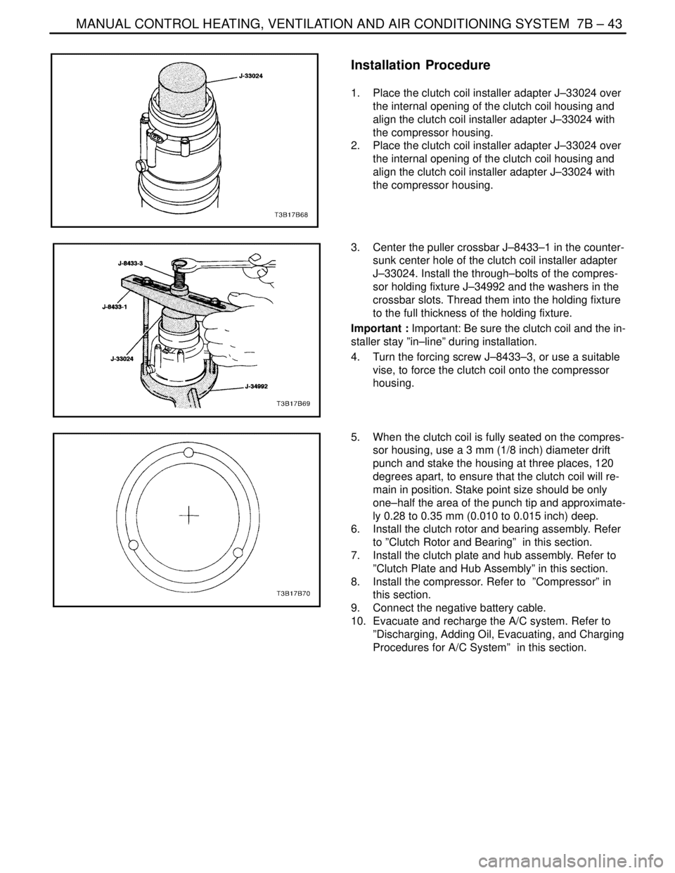
Installation Procedure
1. Place the clutch coil installer adapter J–33024 over
the internal opening of the clutch coil housing and
align the clutch coil installer adapter J–33024 with
the compressor housing.
2. Place the clutch coil installer adapter J–33024 over
the internal opening of the clutch coil housing and
align the clutch coil installer adapter J–33024 with
the compressor housing.
3. Center the puller crossbar J–8433–1 in the counter-
sunk center hole of the clutch coil installer adapter
J–33024. Install the through–bolts of the compres-
sor holding fixture J–34992 and the washers in the
crossbar slots. Thread them into the holding fixture
to the full thickness of the holding fixture.
Important : Important: Be sure the clutch coil and the in-
staller stay ”in–line” during installation.
4. Turn the forcing screw J–8433–3, or use a suitable
vise, to force the clutch coil onto the compressor
housing.
5. When the clutch coil is fully seated on the compres-
sor housing, use a 3 mm (1/8 inch) diameter drift
punch and stake the housing at three places, 120
degrees apart, to ensure that the clutch coil will re-
main in position. Stake point size should be only
one–half the area of the punch tip and approximate-
ly 0.28 to 0.35 mm (0.010 to 0.015 inch) deep.
6. Install the clutch rotor and bearing assembly. Refer
to ”Clutch Rotor and Bearing” in this section.
7. Install the clutch plate and hub assembly. Refer to
”Clutch Plate and Hub Assembly” in this section.
8. Install the compressor. Refer to ”Compressor” in
this section.
9. Connect the negative battery cable.
10. Evacuate and recharge the A/C system. Refer to
”Discharging, Adding Oil, Evacuating, and Charging
Procedures for A/C System” in this section.