Page 1406 of 2643

ZF 4 HP 16 AUTOMATIC TRANSAXLE 5A1 – 57
DAEWOO V–121 BL4
Symptom ActionPossible Cause
Sealing Ring Selector ShaftS Check sealing ring.
S Replace sealing ring as described in the repair
instruction.
O–ring at Socket OutletS Check O–ring.
S Replace O–ring as described in the repair in-
struction.
O–ring and Speed Sensor ConnectionS Check O–ring.
S Replace O–ring as described in the repair in-
struction.
Oil Leak Incorrectly IdentifiedS No oil leak is possible at this point.
Speed Sensor Itself Is LeakingS Check speed sensor.
S Replace speed sensor as described in the re-
pair instruction.
Hair Line Crack at the Piping in the Con-
nection Area, Sealing Ring Fit in Trans-
axle HousingS Pressurize the line with compressed air and
check it.
S Replace lines as described in the repair in-
struction.
O–ring Defective, IncorrectCheck O–ring.
Replace O–rings as described in the repair instruc-
tion.
Plug LooseCheck the Tightening Torque for the screw plug.
Tighten to torque specified in the repair instruction.
Noise
SymptomPossible CauseAction
NoiseTFT Level Too LowS When the TFT level is too low, the gear wheels
from the transaxle oil pump might generate
noise.
S Check the TFT level as described in the repair
instruction and fill to the proper level.
Monolith in Catalytic Converter Has
BrokenS Check according to the exhaust gas diagnostic
procedure or by shaking the catalytic converter
casing.
S Replace catalytic converter if necessary.
Noise from Auxiliaries (e.g. exhaust
system, alternator, drive shafts.)S Check these components; if necessary, elimi-
nate the faults as described in the repair in-
struction
Noise from Tires or Wheel BearingsS Eliminate fault if necessary
Noise from Planetary GearsS Whistling noise on traction and overrun(in first
gear only)caused by high rotating speeds(func-
tionally unavoidable)
Cumulative Tooth Backlash in the Com-
plete Drive LineS Production status. Customer must be con-
vinced.
Jerky Noise of the Parking Lock (e.g.
when the car is standing on a gradient)S Load–reversal reaction
S Apply the handbrake before selection the park-
ing Lock (position P)
Page 1542 of 2643

ZF 4 HP 16 AUTOMATIC TRANSAXLE 5A1 – 193
DAEWOO V–121 BL4
Repairing the Fluid Leak
The following are potential causes for fluid leaks. Check
and repair, as necessary.
S Fasteners are not tightened to specifications.
S Fastener threads and tapped holes are dirty or cor-
roded.
S Gaskets, seals or sleeves are misaligned, dam-
aged, or warped, or scratched.
S The manual shaft is nicked or damaged.
S There is a loose or worn bearing causing excess
seal or sleeve wear.
S Case or component porosity.
S The fluid level is too high.
S There is a plugged vent or a damaged vent tube.
S There is water or coolant in the fluid.
S Fluid drain back holes are plugged.
CASE POROSITY REPAIR
CAUTION : Epoxy adhesive may cause skin irritations
and eye damage. Read and follow all information on
the container label as provided by the manufacturer.
1. Thoroughly clean the area to be repaired with a
cleaning solvent. Air dry the area.
2. Using instructions from the manufacturer, mix a
sufficient amount of epoxy to make the repair.
3. While the transaxle case is still hot, apply the
epoxy. You can use a clean, dry soldering acid
brush to clean the area and also apply the epoxy
cement. Make certain that the area to be repaired is
fully covered.
4. Allow the epoxy cement to dry for 3 hours before
starting the engine.
5. Repeat the fluid leak diagnosis procedures. Refer
to ”Fluid Leak Diagnosis and Repair” in this sec-
tion.
SHIFT CONTROL LEVER ASSEMBLY
Removal Procedure
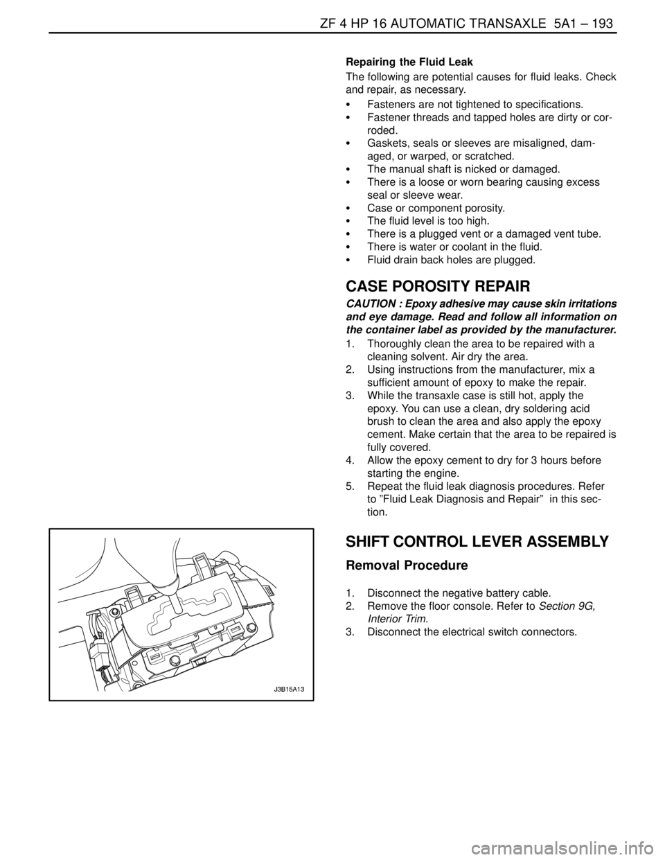
1. Disconnect the negative battery cable.
2. Remove the floor console. Refer to Section 9G,
Interior Trim.
3. Disconnect the electrical switch connectors.
Page 1550 of 2643

ZF 4 HP 16 AUTOMATIC TRANSAXLE 5A1 – 201
DAEWOO V–121 BL4
DRIVE AXLE OIL SEAL
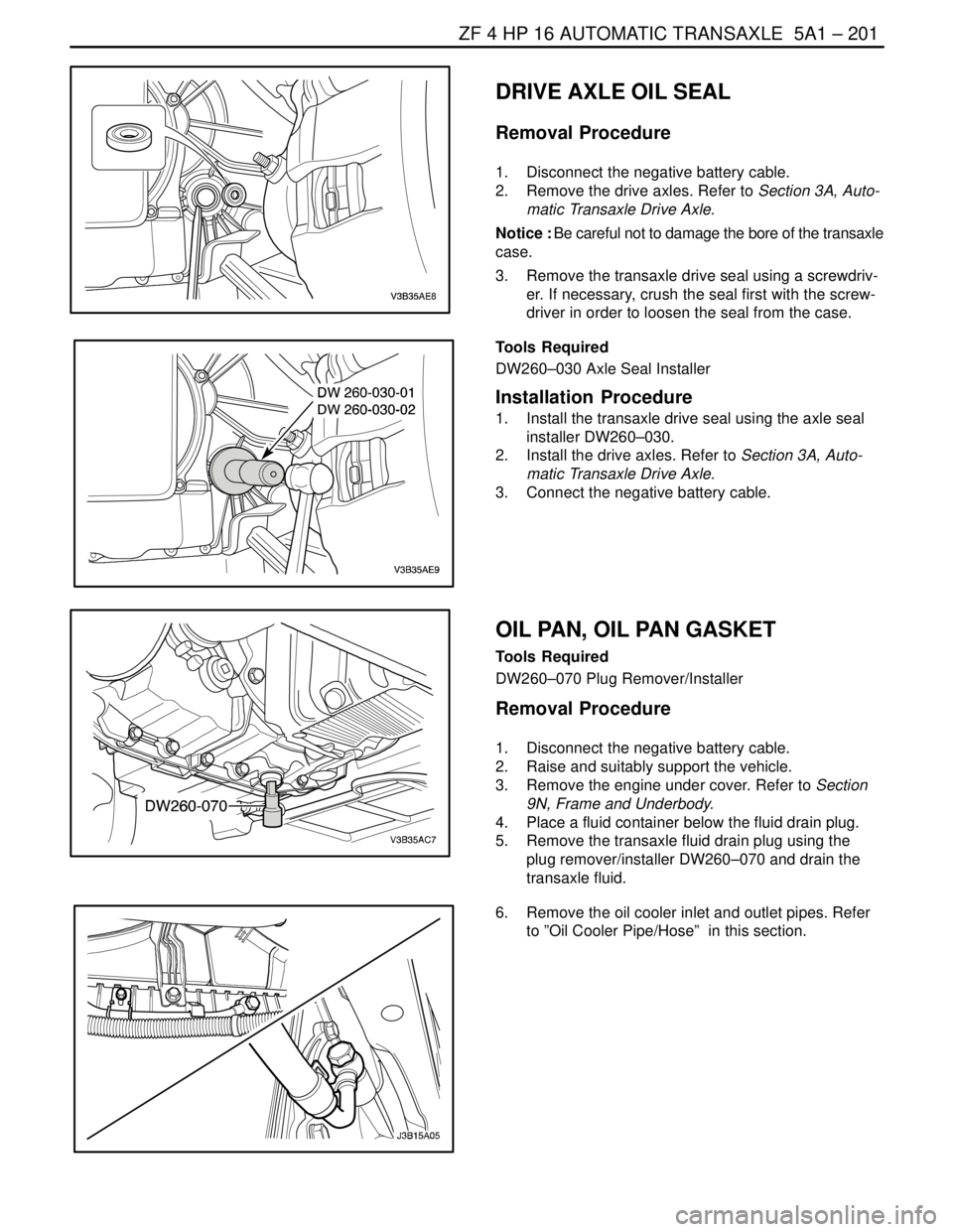
Removal Procedure
1. Disconnect the negative battery cable.
2. Remove the drive axles. Refer to Section 3A, Auto-
matic Transaxle Drive Axle.
Notice : Be careful not to damage the bore of the transaxle
case.
3. Remove the transaxle drive seal using a screwdriv-
er. If necessary, crush the seal first with the screw-
driver in order to loosen the seal from the case.
Tools Required
DW260–030 Axle Seal Installer
Installation Procedure
1. Install the transaxle drive seal using the axle seal
installer DW260–030.
2. Install the drive axles. Refer to Section 3A, Auto-
matic Transaxle Drive Axle.
3. Connect the negative battery cable.
OIL PAN, OIL PAN GASKET
Tools Required
DW260–070 Plug Remover/Installer
Removal Procedure
1. Disconnect the negative battery cable.
2. Raise and suitably support the vehicle.
3. Remove the engine under cover. Refer to Section
9N, Frame and Underbody.
4. Place a fluid container below the fluid drain plug.
5. Remove the transaxle fluid drain plug using the
plug remover/installer DW260–070 and drain the
transaxle fluid.
6. Remove the oil cooler inlet and outlet pipes. Refer
to ”Oil Cooler Pipe/Hose” in this section.
Page 1551 of 2643
5A1 – 202IZF 4 HP 16 AUTOMATIC TRANSAXLE
DAEWOO V–121 BL4
7. Remove the oil pan and oil pan gasket.
Installation Procedure
1. Install the oil pan, oil pan gasket and bolts.
Tighten
Tighten the oil pan bolts to 6 NSm (53 lb–in).
2. Install the oil cooler inlet and outlet pipes. Refer
to”Oil Cooler Pipe/Hose” in this section.
3. Install the transaxle fluid drain plug using the plug
remove/installer DW260–070.
4. Install the engine under cover. Refer to Section 9N,
Frame and Underbody.
5. Refill the transaxle fluid. Refer to ”Transaxle Fluid
Level Checking Procedure” in this section.
6. Connect the negative battery cable.
Page 1552 of 2643
ZF 4 HP 16 AUTOMATIC TRANSAXLE 5A1 – 203
DAEWOO V–121 BL4
CONTROL VALVE BODY ASSEMBLY
Tools Required
DW260–070 Plug Remover/Installer
Removal Procedure
1. Disconnect the negative battery cable.
2. Disconnect the transaxle wiring harness and the
park/neutral position switch electrical connector.
3. Raise and suitably support the vehicle.
4. Remove the engine under cover. Refer to Section
9N, Frame and Underbody.
5. Remove the transaxle fluid drain plug using the
plug remover/installer DW260–070 and drain the
transaxle fluid.
6. Remove the oil pan, oil pan gasket. Refer to ”Oil
Pan, Oil Pan Gasket” in this section.
7. Remove the valve body mounting bolts.
8. Remove the automatic transmission input speed
sensor mounting bolt.
9. Remove the automatic transmission output speed
sensor mounting bolt.
Page 1553 of 2643
5A1 – 204IZF 4 HP 16 AUTOMATIC TRANSAXLE
DAEWOO V–121 BL4
10. Remove the control valve body.
Installation Procedure
1. Install the control valve body and the bolts.
Tighten
Tighten the valve body mounting bolts to 8 NSm (71
lb–in).
2. Install the input speed sensor mounting bolt.
Tighten
Tighten the input speed sensor mounting bolt to 8
NSm (71 lb–in).
3. Install the output speed sensor mounting bolt.
Tighten
Tighten the output speed sensor mounting bolt to 6
NSm (53 lb–in).
4. Install the oil pan and oil pan gasket. Refer to ”Oil
Pan Gasket” in this section.
5. Install the transaxle fluid drain plug using the plug
remove/installer DW260–070.
6. Install the engine under cover. Refer to Section 9N,
Frame and Underbody.
Page 1561 of 2643

5A1 – 212IZF 4 HP 16 AUTOMATIC TRANSAXLE
DAEWOO V–121 BL4
UNIT REPAIR
TORQUE CONVERTER
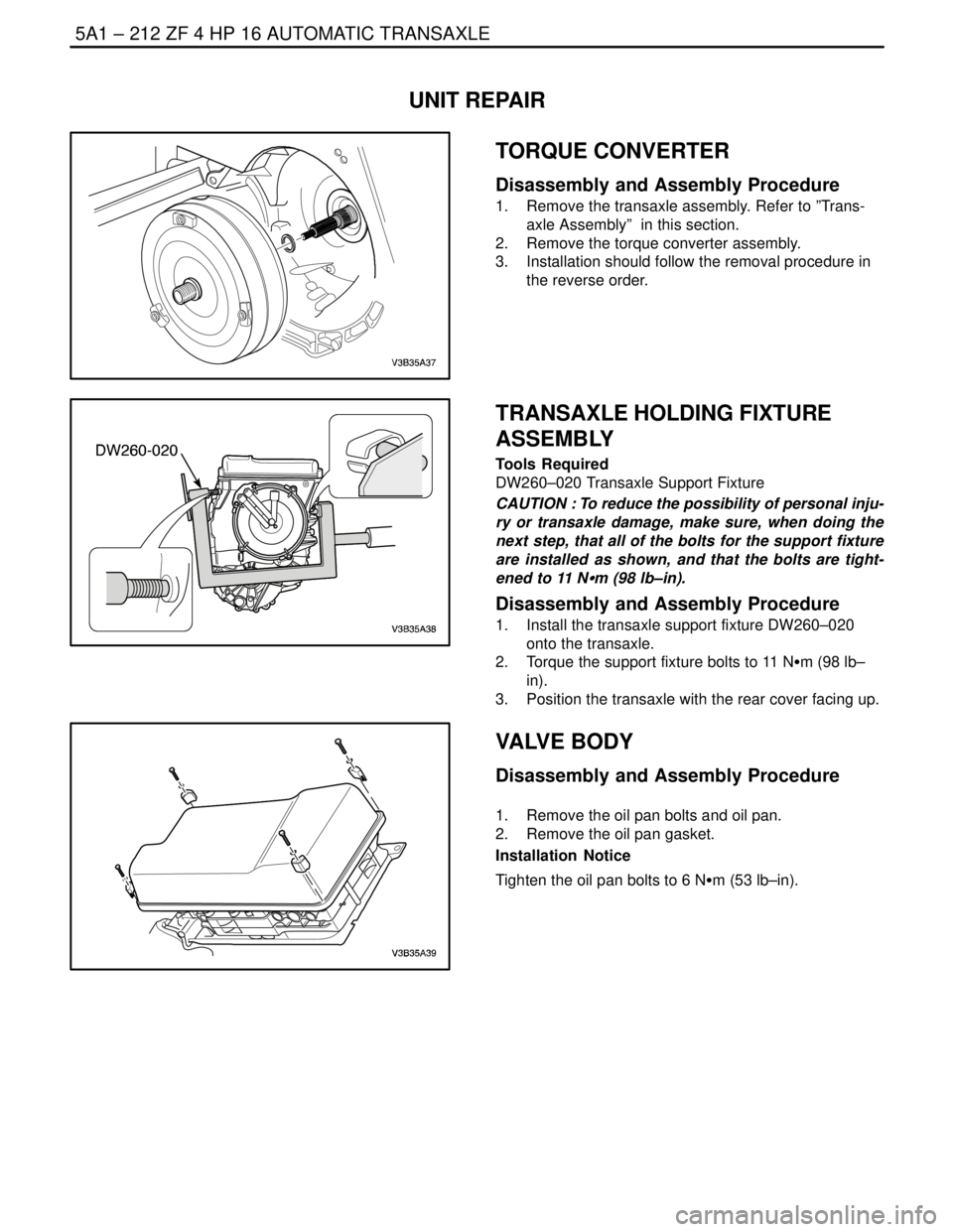
Disassembly and Assembly Procedure
1. Remove the transaxle assembly. Refer to ”Trans-
axle Assembly” in this section.
2. Remove the torque converter assembly.
3. Installation should follow the removal procedure in
the reverse order.
TRANSAXLE HOLDING FIXTURE
ASSEMBLY
Tools Required
DW260–020 Transaxle Support Fixture
CAUTION : To reduce the possibility of personal inju-
ry or transaxle damage, make sure, when doing the
next step, that all of the bolts for the support fixture
are installed as shown, and that the bolts are tight-
ened to 11 NSm (98 lb–in).
Disassembly and Assembly Procedure
1. Install the transaxle support fixture DW260–020
onto the transaxle.
2. Torque the support fixture bolts to 11 NSm (98 lb–
in).
3. Position the transaxle with the rear cover facing up.
VALVE BODY
Disassembly and Assembly Procedure
1. Remove the oil pan bolts and oil pan.
2. Remove the oil pan gasket.
Installation Notice
Tighten the oil pan bolts to 6 NSm (53 lb–in).
Page 1576 of 2643

ZF 4 HP 16 AUTOMATIC TRANSAXLE 5A1 – 227
DAEWOO V–121 BL4
2. Find the disc set’s thickness. Refer to the below
table.
PF
Disc set’s Thickness
3.01~3.19mm1.8mm
3.20~3.48mm2.1mm
3.49~3.88mm2.5mm
3.89~4.08mm2.7mm
4.09~4.30mm3.0mm
PE is 4.20mm so, the disc set’s thickness is
3.0mm.
3. Replace clutch B’s setting disc. (3.0mm)
TORQUE CONVERTER HOUSING
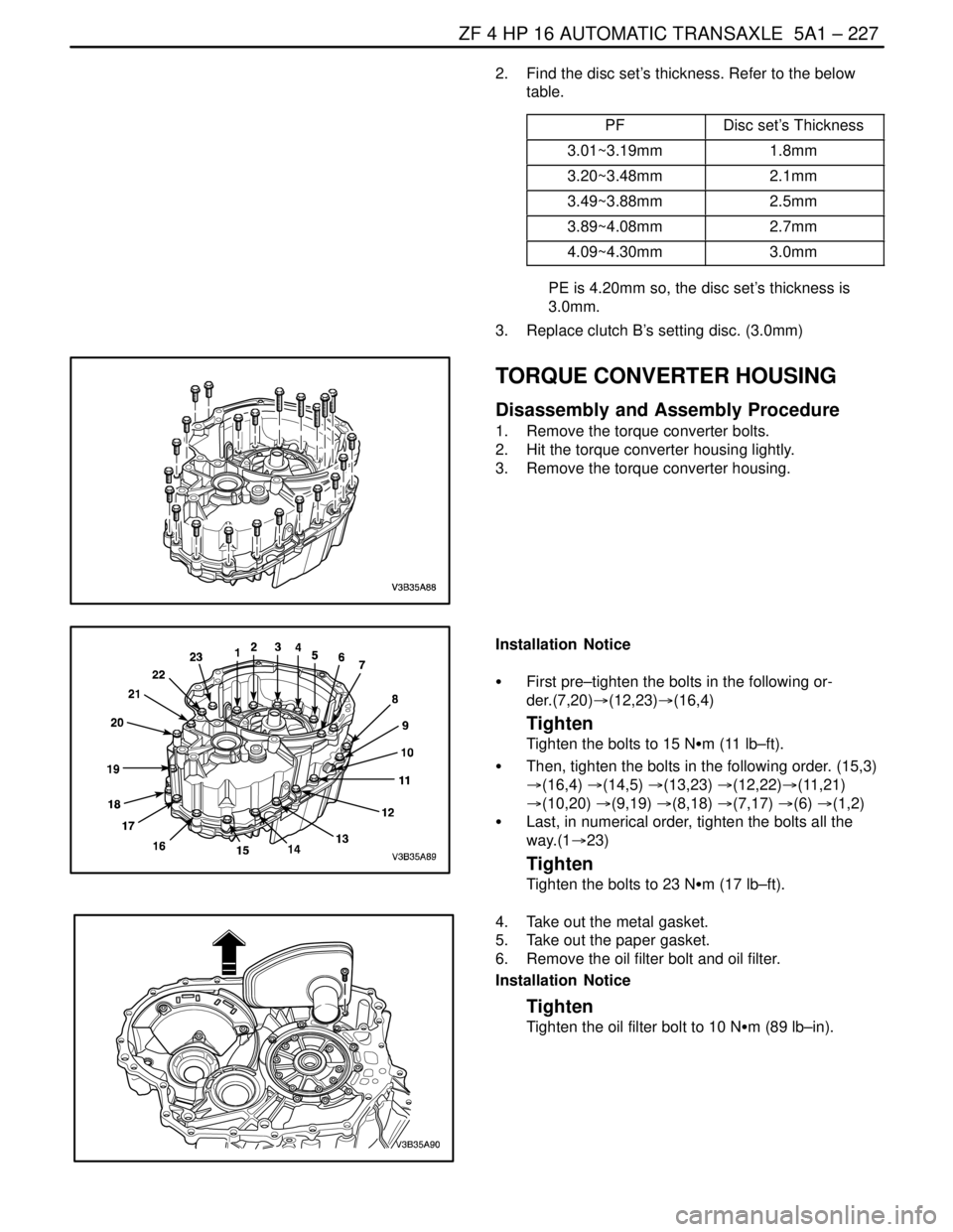
Disassembly and Assembly Procedure
1. Remove the torque converter bolts.
2. Hit the torque converter housing lightly.
3. Remove the torque converter housing.
Installation Notice
S First pre–tighten the bolts in the following or-
der.(7,20)�(12,23)�(16,4)
Tighten
Tighten the bolts to 15 NSm (11 lb–ft).
S Then, tighten the bolts in the following order. (15,3)
�(16,4) �(14,5) �(13,23) �(12,22)�(11,21)
�(10,20) �(9,19) �(8,18) �(7,17) �(6) �(1,2)
S Last, in numerical order, tighten the bolts all the
way.(1�23)
Tighten
Tighten the bolts to 23 NSm (17 lb–ft).
4. Take out the metal gasket.
5. Take out the paper gasket.
6. Remove the oil filter bolt and oil filter.
Installation Notice
Tighten
Tighten the oil filter bolt to 10 NSm (89 lb–in).