2004 DAEWOO NUBIRA belt
[x] Cancel search: beltPage 2349 of 2643
INTERIOR TRIM 9G – 9
DAEWOO V–121 BL4
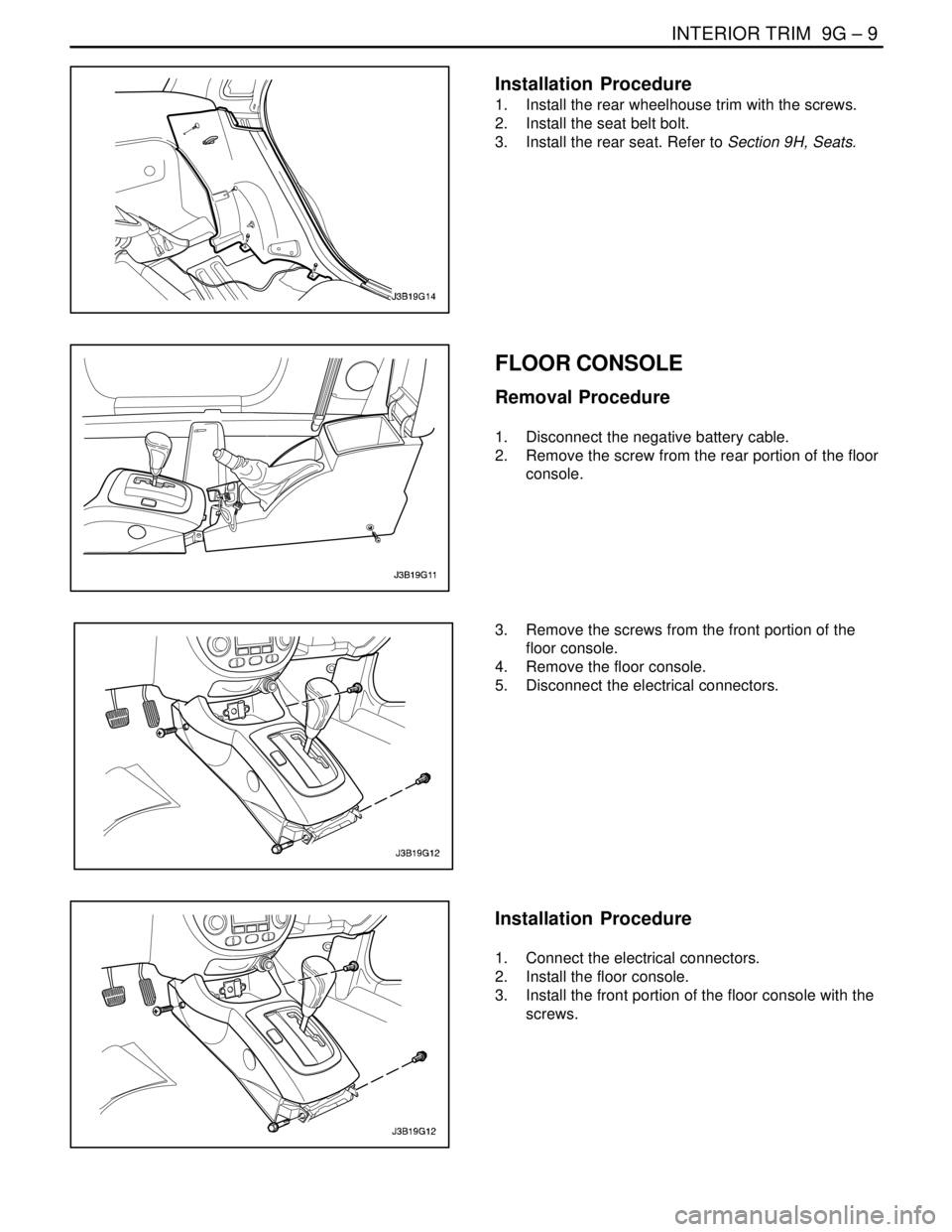
Installation Procedure
1. Install the rear wheelhouse trim with the screws.
2. Install the seat belt bolt.
3. Install the rear seat. Refer to Section 9H, Seats.
FLOOR CONSOLE
Removal Procedure
1. Disconnect the negative battery cable.
2. Remove the screw from the rear portion of the floor
console.
3. Remove the screws from the front portion of the
floor console.
4. Remove the floor console.
5. Disconnect the electrical connectors.
Installation Procedure
1. Connect the electrical connectors.
2. Install the floor console.
3. Install the front portion of the floor console with the
screws.
Page 2350 of 2643
9G – 10IINTERIOR TRIM
DAEWOO V–121 BL4
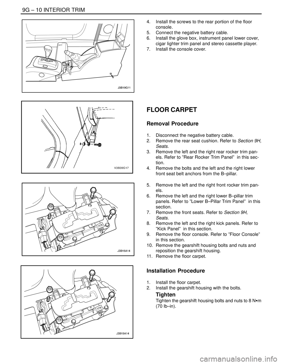
4. Install the screws to the rear portion of the floor
console.
5. Connect the negative battery cable.
6. Install the glove box, instrument panel lower cover,
cigar lighter trim panel and stereo cassette player.
7. Install the console cover.
FLOOR CARPET
Removal Procedure
1. Disconnect the negative battery cable.
2. Remove the rear seat cushion. Refer to Section 9H,
Seats.
3. Remove the left and the right rear rocker trim pan-
els. Refer to ”Rear Rocker Trim Panel” in this sec-
tion.
4. Remove the bolts and the left and the right lower
front seat belt anchors from the B–pillar.
5. Remove the left and the right front rocker trim pan-
els.
6. Remove the left and the right lower B–pillar trim
panels. Refer to ”Lower B–Pillar Trim Panel” in this
section.
7. Remove the front seats. Refer to Section 9H,
Seats.
8. Remove the left and the right kick panels. Refer to
”Kick Panel” in this section.
9. Remove the floor console. Refer to ”Floor Console”
in this section.
10. Remove the gearshift housing bolts and nuts and
reposition the gearshift housing.
11. Remove the floor carpet.
Installation Procedure
1. Install the floor carpet.
2. Install the gearshift housing with the bolts.
Tighten
Tighten the gearshift housing bolts and nuts to 8 NSm
(70 lb–in).
Page 2351 of 2643
INTERIOR TRIM 9G – 11
DAEWOO V–121 BL4
3. Install the floor console. Refer to ”Floor Console” in
this section.
4. Install the left and the right kick panels. Refer to
”Kick Panel” in this section.
5. Install the front seats. Refer to Section 9H, Seats.
6. Install the left and the right lower B–pillar trim pan-
els. Refer to ”Lower B–Pillar Trim Panel” in this
section.
7. Install the left and the right front rocker trim panels.
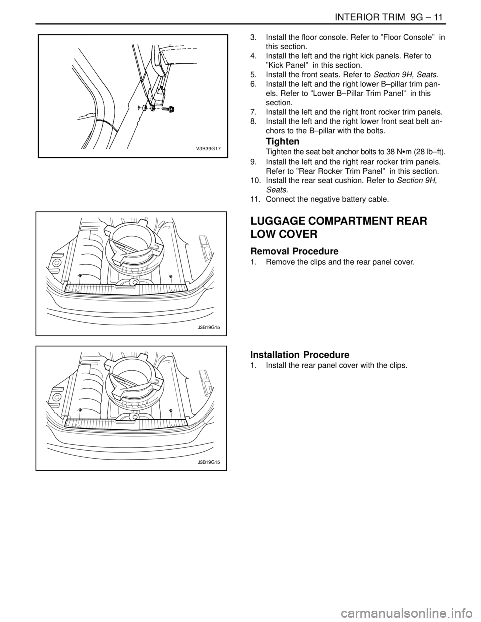
8. Install the left and the right lower front seat belt an-
chors to the B–pillar with the bolts.
Tighten
Tighten the seat belt anchor bolts to 38 NSm (28 lb–ft).
9. Install the left and the right rear rocker trim panels.
Refer to ”Rear Rocker Trim Panel” in this section.
10. Install the rear seat cushion. Refer to Section 9H,
Seats.
11. Connect the negative battery cable.
LUGGAGE COMPARTMENT REAR
LOW COVER
Removal Procedure
1. Remove the clips and the rear panel cover.
Installation Procedure
1. Install the rear panel cover with the clips.
Page 2472 of 2643
SECTION : 9S
BODY REAR END
CAUTION : Disconnect the negative battery cable before removing or installing any electrical unit or when a tool
or equipment could easily come in contact with exposed electrical terminals. Disconnecting this cable will help
prevent personal injury and damage to the vehicle. The ignition must also be in LOCK unless otherwise noted.
TABLE OF CONTENTS
SPECIFICATIONS9S–1 . . . . . . . . . . . . . . . . . . . . . . . . . .
Fastener Tightening Specifications 9S–1. . . . . . . . . . .
MAINTENANCE AND REPAIR9S–2 . . . . . . . . . . . . . . .
ON–VEHICLE SERVICE 9S–2. . . . . . . . . . . . . . . . . . . . .
Fuel Filler Door 9S–2. . . . . . . . . . . . . . . . . . . . . . . . . . . .
Fuel Filler Door Remote Handle and Cable 9S–2. . . .
Rear Deck Lid 9S–4. . . . . . . . . . . . . . . . . . . . . . . . . . . . .
Rear Deck Lid Torque Rods 9S–5. . . . . . . . . . . . . . . . .
Luggage Compartment Lock Cylinder 9S–5. . . . . . . .
Luggage Compartment Lock Striker 9S–6. . . . . . . . . .
Luggage Compartment Lock 9S–6. . . . . . . . . . . . . . . . Weatherstrip 9S–7. . . . . . . . . . . . . . . . . . . . . . . . . . . . . .
Hatchback Weatherstrip 9S–7. . . . . . . . . . . . . . . . . . . .
Hatchback Door 9S–8. . . . . . . . . . . . . . . . . . . . . . . . . . .
Gas Support Assemblies 9S–8. . . . . . . . . . . . . . . . . . .
Hatchback Door Lock Striker 9S–9. . . . . . . . . . . . . . . .
Hatchback Door Lock 9S–9. . . . . . . . . . . . . . . . . . . . . .
GENERAL DESCRIPTION AND SYSTEM
OPERATION9S–10 . . . . . . . . . . . . . . . . . . . . . . . . . . . . .
Fuel Filler Door 9S–10. . . . . . . . . . . . . . . . . . . . . . . . . . .
Rear Deck Lid (Notchback) 9S–10. . . . . . . . . . . . . . . .
Hatchback Door 9S–10. . . . . . . . . . . . . . . . . . . . . . . . . .
SPECIFICATIONS
FASTENER TIGHTENING SPECIFICATIONS
ApplicationNSmLb–FtLb–In
Fuel Filler Door Screws4–35
Fuel Filler Door Remote Cable Handle Cover Screw3–27
Fuel Filler Door Remote Cable Handle Screws10–89
Lower B–Pillar Seat Belt Anchor Bolt3828–
Luggage Compartment Lock Cylinder Nuts8–71
Luggage Compartment Lock Screws6–53
Luggage Compartment Lock Striker Bolts8–71
Rear Deck Lid Bolts10–89
Page 2474 of 2643
BODY REAR END 9S – 3
DAEWOO V–121 BL4
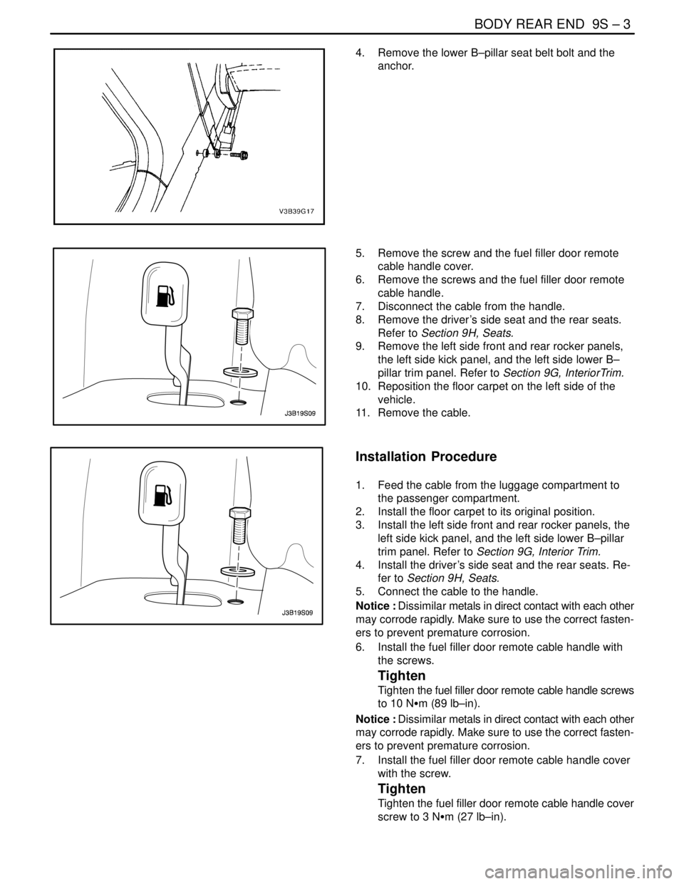
4. Remove the lower B–pillar seat belt bolt and the
anchor.
5. Remove the screw and the fuel filler door remote
cable handle cover.
6. Remove the screws and the fuel filler door remote
cable handle.
7. Disconnect the cable from the handle.
8. Remove the driver’s side seat and the rear seats.
Refer to Section 9H, Seats.
9. Remove the left side front and rear rocker panels,
the left side kick panel, and the left side lower B–
pillar trim panel. Refer to Section 9G, InteriorTrim.
10. Reposition the floor carpet on the left side of the
vehicle.
11. Remove the cable.
Installation Procedure
1. Feed the cable from the luggage compartment to
the passenger compartment.
2. Install the floor carpet to its original position.
3. Install the left side front and rear rocker panels, the
left side kick panel, and the left side lower B–pillar
trim panel. Refer to Section 9G, Interior Trim.
4. Install the driver’s side seat and the rear seats. Re-
fer to Section 9H, Seats.
5. Connect the cable to the handle.
Notice : Dissimilar metals in direct contact with each other
may corrode rapidly. Make sure to use the correct fasten-
ers to prevent premature corrosion.
6. Install the fuel filler door remote cable handle with
the screws.
Tighten
Tighten the fuel filler door remote cable handle screws
to 10 NSm (89 lb–in).
Notice : Dissimilar metals in direct contact with each other
may corrode rapidly. Make sure to use the correct fasten-
ers to prevent premature corrosion.
7. Install the fuel filler door remote cable handle cover
with the screw.
Tighten
Tighten the fuel filler door remote cable handle cover
screw to 3 NSm (27 lb–in).
Page 2475 of 2643
9S – 4IBODY REAR END
DAEWOO V–121 BL4
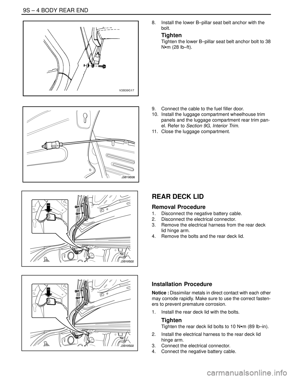
8. Install the lower B–pillar seat belt anchor with the
bolt.
Tighten
Tighten the lower B–pillar seat belt anchor bolt to 38
NSm (28 lb–ft).
9. Connect the cable to the fuel filler door.
10. Install the luggage compartment wheelhouse trim
panels and the luggage compartment rear trim pan-
el. Refer to Section 9G, Interior Trim.
11. Close the luggage compartment.
REAR DECK LID
Removal Procedure
1. Disconnect the negative battery cable.
2. Disconnect the electrical connector.
3. Remove the electrical harness from the rear deck
lid hinge arm.
4. Remove the bolts and the rear deck lid.
Installation Procedure
Notice : Dissimilar metals in direct contact with each other
may corrode rapidly. Make sure to use the correct fasten-
ers to prevent premature corrosion.
1. Install the rear deck lid with the bolts.
Tighten
Tighten the rear deck lid bolts to 10 NSm (89 lb–in).
2. Install the electrical harness to the rear deck lid
hinge arm.
3. Connect the electrical connector.
4. Connect the negative battery cable.
Page 2524 of 2643
2–4 PREPARATIONS OF BODYWORK NUBIRA/LACETTI
2. CHECKPOINTS
S Accurate Inspection of Damaged Parts(Visual)
.
Seat Belts
Always replace the seat belt if :
1. The belt material is cut, punctured, burned or in any
way damaged.
2. The buckle or retractor does not work properly.
3. They were being worn at the time of a collision(also
check for damage at the seat belt anchor points).
4. Their condition is questionable.
.
Front Section :
1. Is there any bending, splitting, denting or other dam-
age to the suspension and its related parts?
2. Is there any deformation of the front panel or radiator
crossmember? Have any of the connected sections
come apart?
3. Are there any creases or distortion in the front wheel-
house or side frame? Have any of the connected sec-
tions come apart?
4. Is there any bending or twisting of the whole front
area?
5. Is there any deformation like creases, bulges, or dents
in the front pillar, dash panel, floor, etc.?
6. Is there any vertical twisting or misaligned clearance
in the door?
7. Is the windshield seal broken?
8. Is there any deformation in the vicinity of the top part
of the roof panel’s center pillar?
9. Is there any damage inside the automobile(is there
any twisting of the dash panel, or anything irregular with
the clearances or sheet–mounting parts)?
10. Is there any damage to the steering wheel? Is there
any deformation in the column and the column–mounted
parts?
11. Is there any oil or water leakage and damage to the en-
gine, transmission or brakes?
12. Is there any irregular noise in the gear changing opera-
tion, engine and transmission rotation?
13. Are there any traces of contact between the engine
block and the center crossmember ?
14. Is there any damage to brake or fuel lines, or wire har-
nesses?Rear Section :
1. Is there any twisting, bulging or denting of the rear floor
any rear bolsters? Have any of the connected sections
come apart?
2. Is there any irregular bulging or denting in the rear
fender?
3. Is there any distortion in the rear inner panel? Is there
any bending and denting in the vicinity of the rear pillar?
4. Is there any distortion or creasing is the rear wheel-
house and arch sections? Have any of the connected
sections come apart?
5. Is there anything irregular in the rear glass seal clear-
ance?
6. Is there any twisting or misalignment of the clearance
of the trunk lid opening section?
7. Is there any bending, splitting, denting or other dam-
age to the suspension and its related parts?
8. Is there any deformation of the rear floor crossmem-
ber, trunk floor panel and back panel? Have any of the
connected sections come apart?
.
Impact Beam :
Always replace the door assembly if :
1. The external force makes the impact beam of door in-
ner deform.
Always replace impact beam if :
2. The external force makes the impact beam of front
bumper and rear bumper deform.
Page 2563 of 2643
NUBIRA/LACETTI ROOF, BACK PANEL AND REAR FLOOR PANEL 5–11
3–2. REPAIR PROCEDURE
1. Remove the related parts.
S Parts to be removed when removing the back panel.
S Rear seat belt and rear seat.
S Muffler, fuel tank and related parts.
S Chassis parts.
S Other related parts.
CAUTION : Do not smoke while working near the
fuel system. Keep open flame away from the fuel
system. If necessary, remove the fuel tank and off
lines.
2. Roughly pull out and straighten the damaged area.
S Check the damage and roughly pull out and re pair the
related back panel, side panel, wheel house inner, rear
longitudinal and other damaged parts with the frame
straightener before remov ing the extension rear floor
panel, rear floor pane and back panel.
S Attach the car to the frame straightener by tightening the
underbody clamps located at the jack up designated
points on the bottom of the frame door opening.
Note : Measure in reference to the dimensions on the
body repair chart.
3. Cut and pry off the back panel.
S The back panel to be cut and pried off when removing
the back panel.
4. Cut and pry off the rear floor and extension rear floor
panel.
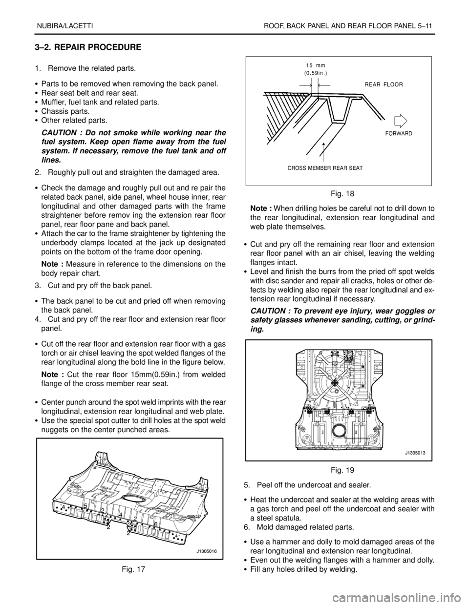
S Cut off the rear floor and extension rear floor with a gas
torch or air chisel leaving the spot welded flanges of the
rear longitudinal along the bold line in the figure below.
Note : Cut the rear floor 15mm(0.59in.) from welded
flange of the cross member rear seat.
S Center punch around the spot weld imprints with the rear
longitudinal, extension rear longitudinal and web plate.
S Use the special spot cutter to drill holes at the spot weld
nuggets on the center punched areas.
Fig. 17
Fig. 18
Note : When drilling holes be careful not to drill down to
the rear longitudinal, extension rear longitudinal and
web plate themselves.
S Cut and pry off the remaining rear floor and extension
rear floor panel with an air chisel, leaving the welding
flanges intact.
S Level and finish the burrs from the pried off spot welds
with disc sander and repair all cracks, holes or other de-
fects by welding also repair the rear longitudinal and ex-
tension rear longitudinal if necessary.
CAUTION : To prevent eye injury, wear goggles or
safety glasses whenever sanding, cutting, or grind-
ing.
Fig. 19
5. Peel off the undercoat and sealer.
S Heat the undercoat and sealer at the welding areas with
a gas torch and peel off the undercoat and sealer with
a steel spatula.
6. Mold damaged related parts.
S Use a hammer and dolly to mold damaged areas of the
rear longitudinal and extension rear longitudinal.
S Even out the welding flanges with a hammer and dolly.
S Fill any holes drilled by welding.