Page 2086 of 2643
AUTOMATIC TEMPERATURE CONTROL HEATING, VENTILATION, AND AIR CONDITIONING SYSTEM 7D – 31
DAEWOO V–121 BL4
CODE 7 – MAX–HI RELAY ERROR
StepActionValue(s)YesNo
11. Turn the ignition switch ON.
2. Set the blower speed manually for maximum
speed.
3. Measure voltage between the ATC controller
terminal A10 and ground.
Is the voltage approximately equal to the specified
value?� 0 ΩGo to Step 3Go to Step 2
2Replace the ATC controller.
Is the repair complete?–System OK–
31. Check the wiring harness associated with the
MAX–HI relay for defects or high terminal re-
sistance.
2. Repair any defects found.
Is the repair complete?–System OKGo to Step 4
4Replace the MAX–HI relay.
Is the repair complete?–System OK–
Page 2087 of 2643
7D – 32IAUTOMATIC TEMPERATURE CONTROL HEATING, VENTILATION, AND AIR CONDITIONING SYSTEM
DAEWOO V–121 BL4
MAINTENANCE AND REPAIR
ON–VEHICLE SERVICE
GENERAL A/C SYSTEM SERVICE PROCEDURES
GENERAL SERVICE PROCEDURES
Refer to Section 7B, Manual Control Heating, Ventilation,
and Air Conditioning System, for details of the following
procedures:
S Discharging, Adding Oil, Evacuating, and Charging
Procedures for A/C System.
S Handling of Refrigerant Lines and Fittings.
S Handling Refrigerant.
S Maintaining Chemical Stability in the Refrigeration
System.
S O–Ring Replacement.
Page 2088 of 2643
IAUTOMATIC TEMPERATURE CONTROL HEATING, VENTILATION, AND AIR CONDITIONING SYSTEM 7D – 33
DAEWOO V–121 BL4
SERVICEABLE COMPONENTS
COMMON HVAC COMPONENTS
Those components used in non–automatic systems are
covered in other sections of this manual.
Refer to Section 7A, Heating and Ventilation System for
the following procedures:
S Blower Motor.
S Heater Hoses.
S Blower Resistor.
S High–Blower Relay.
S Heater/Air Distributor Case Assembly (A/C Mod-
ule).
S Heater Core.
Refer to Section 7B, Manual Control Heating, Ventilation,
and Air Conditioning System, for the following proce-
dures:
S A/C Pressure Transducer.
S A/C Compressor Relay.
S Air Filter.
S A/C Expansion Valve.
S A/C High–Pressure Pipe Line.
S Evaporator Core.
S A/C Suction Hose Assembly.
S A/C Discharge Hose–Compressor to Condenser.
S Compressor.
S Condenser.
S Receiver–Dryer.
AUTOMATIC TEMPERATURE
CONTROL ASSEMBLY
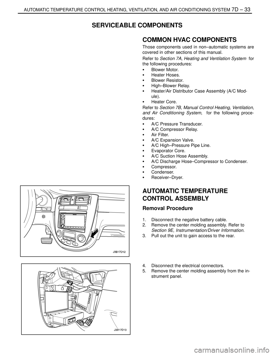
Removal Procedure
1. Disconnect the negative battery cable.
2. Remove the center molding assembly. Refer to
Section 9E, Instrumentation/Driver Information.
3. Pull out the unit to gain access to the rear.
4. Disconnect the electrical connectors.
5. Remove the center molding assembly from the in-
strument panel.
Page 2089 of 2643
7D – 34IAUTOMATIC TEMPERATURE CONTROL HEATING, VENTILATION, AND AIR CONDITIONING SYSTEM
DAEWOO V–121 BL4
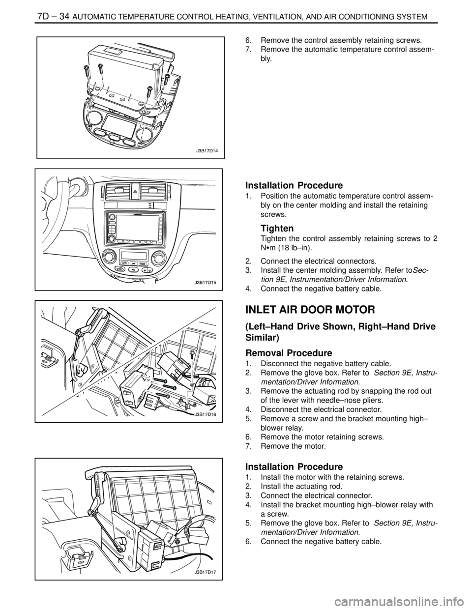
6. Remove the control assembly retaining screws.
7. Remove the automatic temperature control assem-
bly.
Installation Procedure
1. Position the automatic temperature control assem-
bly on the center molding and install the retaining
screws.
Tighten
Tighten the control assembly retaining screws to 2
NSm (18 lb–in).
2. Connect the electrical connectors.
3. Install the center molding assembly. Refer toSec-
tion 9E, Instrumentation/Driver Information.
4. Connect the negative battery cable.
INLET AIR DOOR MOTOR
(Left–Hand Drive Shown, Right–Hand Drive
Similar)
Removal Procedure
1. Disconnect the negative battery cable.
2. Remove the glove box. Refer to Section 9E, Instru-
mentation/Driver Information.
3. Remove the actuating rod by snapping the rod out
of the lever with needle–nose pliers.
4. Disconnect the electrical connector.
5. Remove a screw and the bracket mounting high–
blower relay.
6. Remove the motor retaining screws.
7. Remove the motor.
Installation Procedure
1. Install the motor with the retaining screws.
2. Install the actuating rod.
3. Connect the electrical connector.
4. Install the bracket mounting high–blower relay with
a screw.
5. Remove the glove box. Refer to Section 9E, Instru-
mentation/Driver Information.
6. Connect the negative battery cable.
Page 2090 of 2643
IAUTOMATIC TEMPERATURE CONTROL HEATING, VENTILATION, AND AIR CONDITIONING SYSTEM 7D – 35
DAEWOO V–121 BL4
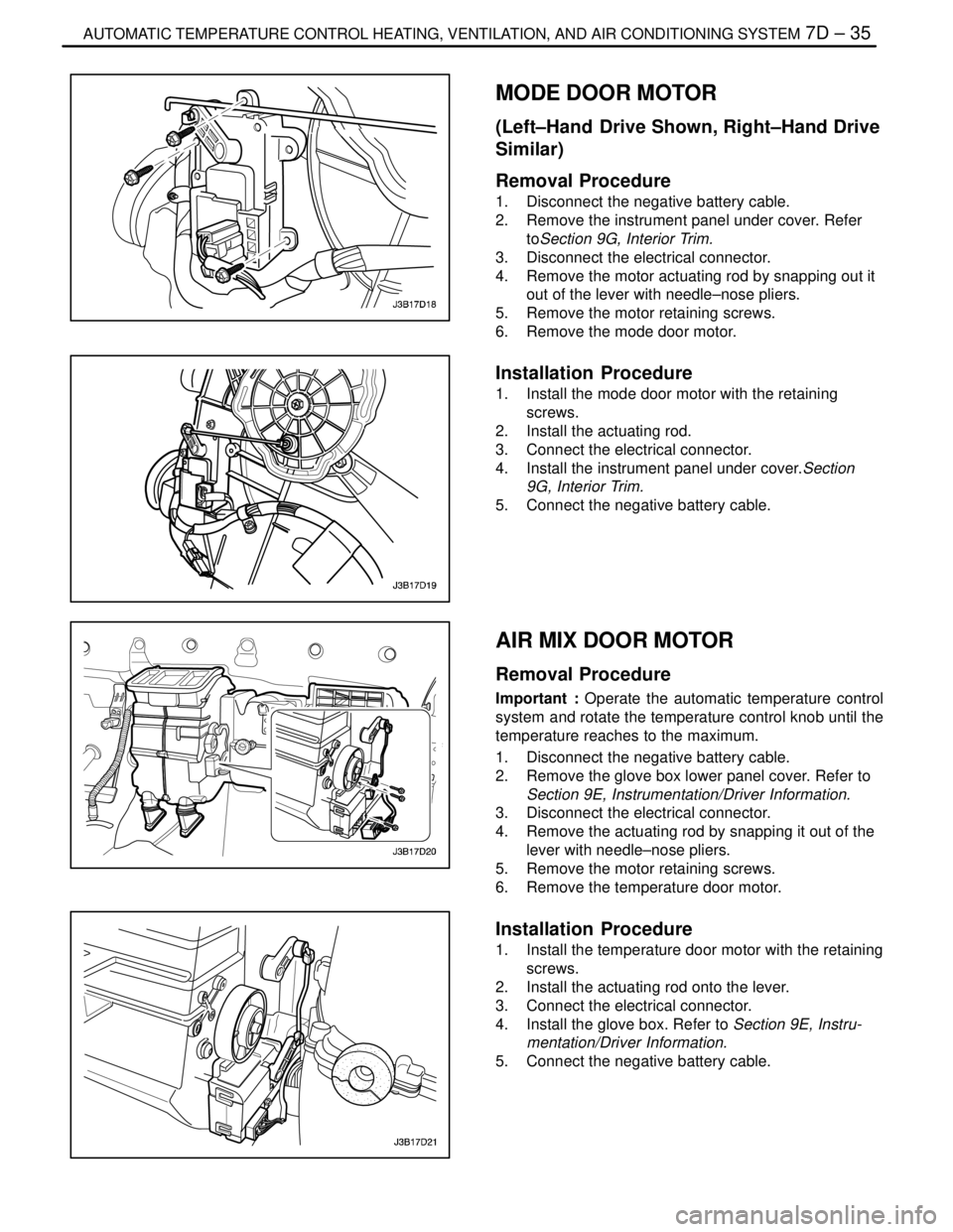
MODE DOOR MOTOR
(Left–Hand Drive Shown, Right–Hand Drive
Similar)
Removal Procedure
1. Disconnect the negative battery cable.
2. Remove the instrument panel under cover. Refer
toSection 9G, Interior Trim.
3. Disconnect the electrical connector.
4. Remove the motor actuating rod by snapping out it
out of the lever with needle–nose pliers.
5. Remove the motor retaining screws.
6. Remove the mode door motor.
Installation Procedure
1. Install the mode door motor with the retaining
screws.
2. Install the actuating rod.
3. Connect the electrical connector.
4. Install the instrument panel under cover.Section
9G, Interior Trim.
5. Connect the negative battery cable.
AIR MIX DOOR MOTOR
Removal Procedure
Important : Operate the automatic temperature control
system and rotate the temperature control knob until the
temperature reaches to the maximum.
1. Disconnect the negative battery cable.
2. Remove the glove box lower panel cover. Refer to
Section 9E, Instrumentation/Driver Information.
3. Disconnect the electrical connector.
4. Remove the actuating rod by snapping it out of the
lever with needle–nose pliers.
5. Remove the motor retaining screws.
6. Remove the temperature door motor.
Installation Procedure
1. Install the temperature door motor with the retaining
screws.
2. Install the actuating rod onto the lever.
3. Connect the electrical connector.
4. Install the glove box. Refer to Section 9E, Instru-
mentation/Driver Information.
5. Connect the negative battery cable.
Page 2091 of 2643
7D – 36IAUTOMATIC TEMPERATURE CONTROL HEATING, VENTILATION, AND AIR CONDITIONING SYSTEM
DAEWOO V–121 BL4
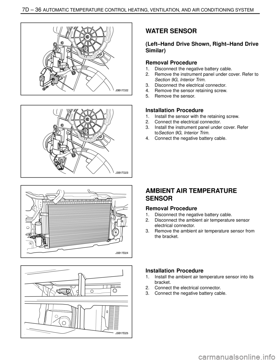
WATER SENSOR
(Left–Hand Drive Shown, Right–Hand Drive
Similar)
Removal Procedure
1. Disconnect the negative battery cable.
2. Remove the instrument panel under cover. Refer to
Section 9G, Interior Trim.
3. Disconnect the electrical connector.
4. Remove the sensor retaining screw.
5. Remove the sensor.
Installation Procedure
1. Install the sensor with the retaining screw.
2. Connect the electrical connector.
3. Install the instrument panel under cover. Refer
toSection 9G, Interior Trim.
4. Connect the negative battery cable.
AMBIENT AIR TEMPERATURE
SENSOR
Removal Procedure
1. Disconnect the negative battery cable.
2. Disconnect the ambient air temperature sensor
electrical connector.
3. Remove the ambient air temperature sensor from
the bracket.
Installation Procedure
1. Install the ambient air temperature sensor into its
bracket.
2. Connect the electrical connector.
3. Connect the negative battery cable.
Page 2092 of 2643
IAUTOMATIC TEMPERATURE CONTROL HEATING, VENTILATION, AND AIR CONDITIONING SYSTEM 7D – 37
DAEWOO V–121 BL4
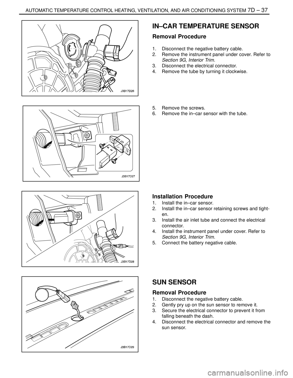
IN–CAR TEMPERATURE SENSOR
Removal Procedure
1. Disconnect the negative battery cable.
2. Remove the instrument panel under cover. Refer to
Section 9G, Interior Trim.
3. Disconnect the electrical connector.
4. Remove the tube by turning it clockwise.
5. Remove the screws.
6. Remove the in–car sensor with the tube.
Installation Procedure
1. Install the in–car sensor.
2. Install the in–car sensor retaining screws and tight-
en.
3. Install the air inlet tube and connect the electrical
connector.
4. Install the instrument panel under cover. Refer to
Section 9G, Interior Trim.
5. Connect the battery negative cable.
SUN SENSOR
Removal Procedure
1. Disconnect the negative battery cable.
2. Gently pry up on the sun sensor to remove it.
3. Secure the electrical connector to prevent it from
falling beneath the dash.
4. Disconnect the electrical connector and remove the
sun sensor.
Page 2093 of 2643
7D – 38IAUTOMATIC TEMPERATURE CONTROL HEATING, VENTILATION, AND AIR CONDITIONING SYSTEM
DAEWOO V–121 BL4
Installation Procedure
1. Connect the electrical connector.
2. Insert and press the sun sensor into position in the
dash.
3. Connect the negative battery cable.