Page 1958 of 2643
6E – 4ISTEERING WHEEL AND COLUMN
DAEWOO V–121 BL4
Page 1959 of 2643

STEERING WHEEL AND COLUMN 6E – 5
DAEWOO V–121 BL4
Column
Noise in the Column
ChecksAction
Check the steering gear–to–column joints for improper
installation.Tighten the steering shaft universal joint pinch bolts.
Replace the steering shaft joints as needed.
Check the steering shaft bearing for wear or damage.Replace the steering shaft bearing.
Check the spherical joint for lack of lubrication.Lubricate the spherical joint.
Check the steering shaft for lack of lubrication.Lubricate the steering shaft bearing.
Check the shaft lock snap ring for improper seating.Adjust the shaft lock snap ring. Replace the shaft lock snap
ring as needed.
High Steering Shaft Effort
ChecksAction
Check the steering shaft bearing for wear or damage.Replace the steering shaft bearing.
Check for an improperly installed or deformed dust seal.Replace the dust seal.
Check for a damaged upper or lower bearing.Replace the upper or the lower bearing.
Check the steering shaft universal joints for a lack of free
movement.Lubricate the steering shaft universal joints. Replace the
steering shaft universal joints as needed.
Lash in the Steering Column
ChecksAction
Check the steering column bracket mounting bolts for im-
proper installation.Tighten the steering column bracket mounting bolts.
Check for broken weld nuts on the steering column jacket.Replace the steering column jacket.
Check for loose steering column housing–to–steering col-
umn jacket support screws.Tighten the support screws.
Loose Steering Wheel
ChecksAction
Check for excessive clearance between the holes in the
steering wheel support or the housing and the pivot–pin di-
ameters.Replace the pivot pins with pivot pins of the correct size.
Check to see if the upper bearing is seated correctly in the
housing.Correctly seat the upper bearing. Replace the upper bear-
ing as needed.
Check for loose steering column housing support screws.Tighten the steering column housing support screws.
Noise When Tilting the Column
ChecksAction
Check for worn upper tilt bumpers.Replace the upper tilt bumpers.
Check for tilt spring binding.Adjust the tilt spring. Replace the tilt spring as needed.
Page 1960 of 2643

6E – 6ISTEERING WHEEL AND COLUMN
DAEWOO V–121 BL4
Turn Signal/Dimmer Switch
Turn Signal Will Not Stay in the Turn Position
ChecksAction
Check the turn signal switch for an improper installation.Remove and inspect the turn signal switch. Reinstall the
switch.
Check the cancelling mechanism for broken or missing
components.Replace the cancelling mechanism.
Check the turn signal switch housing for foreign material.Remove any foreign material.
Turn Signal Will Not Cancel
ChecksAction
Check the cancelling mechanism for broken or missing
components.Replace the cancelling mechanism.
Turn Signal/Dimmer Switch Difficult to Operate
ChecksAction
Check the turn signal/dimmer switch and turn signal/dim-
mer switch lever for improper installation.Remove and inspect the turn signal/dimmer switch and
signal/dimmer switch lever. Reinstall the signal/dimmer
switch and signal/dimmer switch lever.
Check the signal/dimmer switch housing for foreign mate-
rial.Remove any foreign material.
Turn Signal Will Not Indicate Lane Change
ChecksAction
Check for a broken lane change pressure pad or a broken
spring hanger.Replace the lane change pressure pad or the spring hang-
er.
Check for improper functioning of the lane change spring.Replace the lane change spring.
Check the turn signal switch for improper installation.Replace the turn signal switch.
No Turn Signal Lights
ChecksAction
Check for an inoperative turn signal flasher.Replace the turn signal flasher.
Check for a faulty turn signal switch.Replace the turn signal switch.
Check the chassis–to–column connector for an improper
connection.Reconnect the chassis–to–column connector.
Turn Indicator Lights On, but Not Flashing
ChecksAction
Check for an inoperative turn signal flasher.Replace the turn signal flasher.
Check for a faulty turn signal switch.Replace the turn signal switch.
Check the chassis–to–column connector for an improper
connection.Reconnect the chassis–to–column connector.
Page 1961 of 2643

STEERING WHEEL AND COLUMN 6E – 7
DAEWOO V–121 BL4
Front or Rear Turn Signal Lights Not Flashing
ChecksAction
Check for a faulty turn signal switch.Replace the turn signal switch.
Check the chassis–to–column connector for an improper
connection.Reconnect the chassis–to–column connector.
Turn Signal Lights Flash Very Slowly
ChecksAction
Check the chassis–to–column connector for an improper
connection.Reconnect the chassis–to–column connector.
Ignition Switch
Electrical System Will Not Function
ChecksAction
Check the ignition switch for damage.Replace the ignition switch.
Check the ignition switch for improper installation.Remove and inspect the ignition switch. Reinstall the igni-
tion switch.
Check the ignition switch electrical connector for improper
installation.Reconnect the ignition switch electrical connector.
Replace the ignition switch electrical connector.
Ignition Switch Will Not Turn
ChecksAction
Check the ignition switch for damage.Replace the ignition switch.
Check the ignition switch for improper installation.Remove and inspect the ignition switch. Reinstall the igni-
tion switch.
Wiper Lever and Switch
Switch Inoperative: No LOW, HIGH, INTERMITTENT or WASH
ChecksAction
Check the wiper lever and switch for damage.Replace the wiper lever and switch.
Check the wiper lever and switch for improper installation.Remove and inspect the wiper lever and switch.
Reinstall the wiper lever and switch.
Page 1962 of 2643
6E – 8ISTEERING WHEEL AND COLUMN
DAEWOO V–121 BL4
MAINTENANCE AND REPAIR
ON–VEHICLE SERVICE
HEADLAMP/TURN SIGNAL SWITCH
AND LEVER
(Left–Hand Drive Shown, Right–Hand Dirve
Similar)
Removal Procedure
1. Disconnect the negative battery cable.
2. Remove the upper and the lower steering column
cover panel screws.
3. Remove the upper and the lower steering column
cover panels.
4. Remove the turn signal switch by pushing the tabs
on the top and the bottom of the switch housing.
5. Disconnect the electrical connections from the turn
signal switch.
Installation Procedure
1. Connect the electrical connections to the turn signal
switch.
2. Install the turn signal switch by snapping it into the
switch housing.
Page 1963 of 2643

STEERING WHEEL AND COLUMN 6E – 9
DAEWOO V–121 BL4
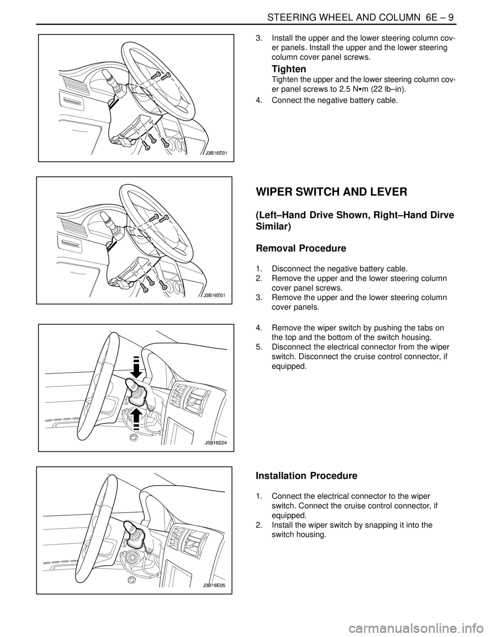
3. Install the upper and the lower steering column cov-
er panels. Install the upper and the lower steering
column cover panel screws.
Tighten
Tighten the upper and the lower steering column cov-
er panel screws to 2.5 NSm (22 lb–in).
4. Connect the negative battery cable.
WIPER SWITCH AND LEVER
(Left–Hand Drive Shown, Right–Hand Dirve
Similar)
Removal Procedure
1. Disconnect the negative battery cable.
2. Remove the upper and the lower steering column
cover panel screws.
3. Remove the upper and the lower steering column
cover panels.
4. Remove the wiper switch by pushing the tabs on
the top and the bottom of the switch housing.
5. Disconnect the electrical connector from the wiper
switch. Disconnect the cruise control connector, if
equipped.
Installation Procedure
1. Connect the electrical connector to the wiper
switch. Connect the cruise control connector, if
equipped.
2. Install the wiper switch by snapping it into the
switch housing.
Page 1964 of 2643

6E – 10ISTEERING WHEEL AND COLUMN
DAEWOO V–121 BL4
3. Install the upper and the lower steering column cov-
er panels. Install the upper and the lower steering
column cover panel screws.
Tighten
Tighten the upper and the lower steering column cov-
er panel screws to 2.5 NSm (22 lb–in).
4. Connect the negative battery cable.
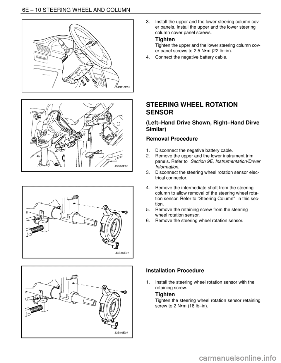
STEERING WHEEL ROTATION
SENSOR
(Left–Hand Drive Shown, Right–Hand Dirve
Similar)
Removal Procedure
1. Disconnect the negative battery cable.
2. Remove the upper and the lower instrument trim
panels. Refer to Section 9E, Instrumentation/Driver
Information.
3. Disconnect the steering wheel rotation sensor elec-
trical connector.
4. Remove the intermediate shaft from the steering
column to allow removal of the steering wheel rota-
tion sensor. Refer to ”Steering Column” in this sec-
tion.
5. Remove the retaining screw from the steering
wheel rotation sensor.
6. Remove the steering wheel rotation sensor.
Installation Procedure
1. Install the steering wheel rotation sensor with the
retaining screw.
Tighten
Tighten the steering wheel rotation sensor retaining
screw to 2 NSm (18 lb–in).
Page 1965 of 2643
STEERING WHEEL AND COLUMN 6E – 11
DAEWOO V–121 BL4
2. Install the intermediate shaft onto the steering col-
umn. Refer to ”Steering Column” in this section.
3. Connect the steering wheel rotation sensor electri-
cal connector.
4. Install the upper and the lower instrument trim pan-
els. Refer to Section 9E, Instrumentation/Driver
Information.
5. Connect the negative battery cable.
STEERING WHEEL WITHOUT SIR
Tools Required
KM–210–A Steering Wheel Puller
Removal Procedure
1. Disconnect the negative battery cable.
2. Rotate the steering wheel to allow access to the
steering wheel horn cap screw. Remove the horn
cap screw.
3. Rotate the steering wheel to allow access to the
other steering wheel horn cap screw. Remove the
horn cap screw.
4. Remove the steering wheel horn cap and discon-
nect the horn leads.
5. Remove the steering wheel nut and the retaining
clip.