Page 1881 of 2643
FIVE–SPEED MANUAL TRANSAXLE 5B – 57
DAEWOO V–121 BL4
8. Install the third–fourth gearshift rod/fork holding pin.
9. Install the support bracket onto the bearing plate.
10. Install the first–second gearshift rod/fork onto the
bearing plate.
11. Install the first–second gearshift fork holding pin.
Page 1882 of 2643
5B – 58IFIVE–SPEED MANUAL TRANSAXLE
DAEWOO V–121 BL4
12. Install the support bracket bolts.
Tighten
Tighten the support bracket bolts to 7 NSm (62 lb–in).
13. Install the reverse gearshift rod/fork onto the bear-
ing plate.
14. Install the reverse gearshift rod/fork holding pin.
15. Install the rod lock pin and spring into the small plug
hole.
Page 1883 of 2643
FIVE–SPEED MANUAL TRANSAXLE 5B – 59
DAEWOO V–121 BL4
16. Install the fourth–gearshift rod plugs.
17. Install the bolts and the fifth–gearshift connector
onto the bearing plate, using the pawl.
Tighten
Tighten the fifth–gearshift connector bolts to 7 NSm
(62 lb–in).
18. Install the input drive fifth gear using the installer
KM–554 and the installer sleeve KM–334.
19. Install the snap rings securing the fifth–drive gear.
Page 1884 of 2643
5B – 60IFIVE–SPEED MANUAL TRANSAXLE
DAEWOO V–121 BL4
20. Install the thrust washers, the retaining ring, and
the needle bearing into the mainshaft–driven fifth–
gear assembly.
21. Install the brass synchronizer ring onto the main-
shaft– driven fifth–gear assembly.
22. Install the mainshaft–driven fifth–gear assembly.
23. Install the fifth–drive gear synchronizer gear and
the synchronizer sleeve using installer KM–554.
24. Install the snap ring holding the fifth speed–driven
assembly.
Page 1885 of 2643
FIVE–SPEED MANUAL TRANSAXLE 5B – 61
DAEWOO V–121 BL4
25. Install the bolts and the fifth–gear fork onto the
bearing plate.
Tighten
Tighten the fifth–gear fork bolts to 22 NSm (16 lb–ft).
26. Remove the bearing plate from the fixture KM–552.
27. Shift the transaxle into second gear.
28. Install the bearing plate, with the shafts attached,
into the case.
29. Install the bearing plate bolts.
Tighten
Tighten the bearing plate bolts to 22 NSm (16 lb–ft).
30. Install the speedometer–driven gear and the
speedometer–housing retaining bolt into the trans-
axle housing.
Tighten
Tighten the speedometer housing retaining bolt to 4
NSm (35 lb–in).
Page 1886 of 2643
5B – 62IFIVE–SPEED MANUAL TRANSAXLE
DAEWOO V–121 BL4
31. Bolt the gearshift lever cover to the fixture KM–552.
32. Position the fixture into the base KM–113–2.
33. Install the gearshift rod, the shift finger lever, and
the gearshift lever pin.
34. Install the snap ring, the bushing, the spring, and
the intermediate lever.
35. Remove the gearshift lever cover from the base
KM–113–2 and the fixture KM–552.
36. Shift the transaxle into NEUTRAL.
37. Install the gearshift lever cover and the gearshift
lever cover bolts.
Tighten
Tighten the gearshift lever cover bolts to 22 NSm (16
lb–ft).
38. Install the transaxle cover and the transaxle cover
bolts.
Tighten
Tighten the transaxle cover bolts to 18 NSm (13 lb–ft).
39. Install the transaxle into the vehicle. Refer to
”Transaxle Assembly” in this section.
Page 1887 of 2643
FIVE–SPEED MANUAL TRANSAXLE 5B – 63
DAEWOO V–121 BL4
GENERAL DESCRIPTION
AND SYSTEM OPERATION
FIVE–SPEED MANUAL TRANSAXLE
This five–speed transaxle assembly is a transmission of
constant–mesh design.
Combined in the assembly are:
S All forward gears.
S The reverse gear.
S The differential output.
The basic components of the five–speed transaxle as-
sembly units are the:
S Transaxle case.
S Input shaft.
S Input shaft gears.S Output shaft.
S Output shaft gears.
S Ring gear and differential assembly.
Forward Gear
Shifting to a forward gear is accomplished through a com-
bination of synchronizers with blocker rings controlled by
sliding shift forks.
Reverse Gear
Reverse gear is not synchronized and uses a sliding idler
gear arrangement.
Differential Assembly
The differential is a conventional arrangement of gears
that is supported by tapered roller bearings. The final out-
put gear turns the ring gear and differential assembly
which turns the drive axle shafts.
Page 1895 of 2643

5C – 8ICLUTCH
DAEWOO V–121 BL4
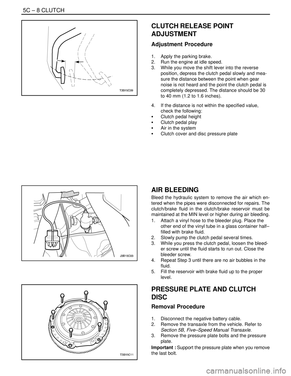
CLUTCH RELEASE POINT
ADJUSTMENT
Adjustment Procedure
1. Apply the parking brake.
2. Run the engine at idle speed.
3. While you move the shift lever into the reverse
position, depress the clutch pedal slowly and mea-
sure the distance between the point when gear
noise is not heard and the point the clutch pedal is
completely depressed. The distance should be 30
to 40 mm (1.2 to 1.6 inches).
4. If the distance is not within the specified value,
check the following:
S Clutch pedal height
S Clutch pedal play
S Air in the system
S Clutch cover and disc pressure plate
AIR BLEEDING
Bleed the hydraulic system to remove the air which en-
tered when the pipes were disconnected for repairs. The
clutch/brake fluid in the clutch/brake reservoir must be
maintained at the MIN level or higher during air bleeding.
1. Attach a vinyl hose to the bleeder plug. Place the
other end of the vinyl tube in a glass container half–
filled with brake fluid.
2. Slowly pump the clutch pedal several times.
3. While you press the clutch pedal, loosen the bleed-
er screw until the fluid starts to run out. Close the
bleeder screw.
4. Repeat Step 3 until there are no air bubbles in the
fluid.
5. Fill the reservoir with brake fluid up to the proper
level.
PRESSURE PLATE AND CLUTCH
DISC
Removal Procedure
1. Disconnect the negative battery cable.
2. Remove the transaxle from the vehicle. Refer to
Section 5B, Five–Speed Manual Transaxle.
3. Remove the pressure plate bolts and the pressure
plate.
Important : Support the pressure plate when you remove
the last bolt.