Page 2411 of 2643

9N – 8IFRAME AND UNDERBODY
DAEWOO V–121 BL4
GENERAL DESCRIPTION
AND SYSTEM OPERATION
GENERAL BODY CONSTRUCTION
This vehicle is constructed with a unitized body which in-
corporates integral front and rear frame side rails.
The front suspension lower control arms are bolted to and
retained by supports, one each on the right and left sides.
The front suspension lower control arm supports are at-
tached to the underbody with three bolts at two locations.
The engine is bolted to the integral front side rails. The
suspension strut towers must be dimensionally correct in
relation to the remainder of the underbody in order to main-
tain specified suspension strut and caster/ camber angles.Since the individual underbody parts contribute directly to
the overall strength of the body, it is essential to observe
proper welding techniques during service repair opera-
tions. The underbody parts should be properly sealed and
rustproofed whenever body repair operations destroy or
damage the original sealing and rustproofing. When rust-
proofing critical underbody parts, use a good–quality type
of air–dry primer, such as a corrosion–resistant chromate
or an equivalent material. Combination–type primer/sur-
facers are not recommended.
ENGINE UNDER COVERS
The engine under covers are molded pieces of plastic that
serve as shields for the underside of the engine. The cov-
ers help protect the engine from small rocks, gravel and
other objects that would otherwise come into contact with
the engine during normal driving conditions.
Page 2466 of 2643

BODY FRONT END 9R – 5
DAEWOO V–121 BL4
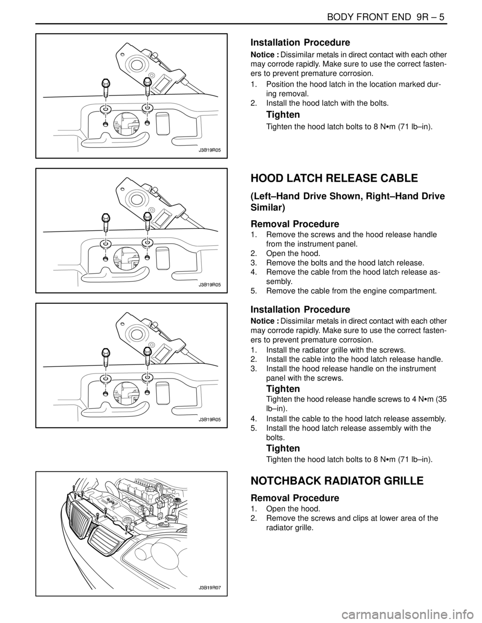
Installation Procedure
Notice : Dissimilar metals in direct contact with each other
may corrode rapidly. Make sure to use the correct fasten-
ers to prevent premature corrosion.
1. Position the hood latch in the location marked dur-
ing removal.
2. Install the hood latch with the bolts.
Tighten
Tighten the hood latch bolts to 8 NSm (71 lb–in).
HOOD LATCH RELEASE CABLE
(Left–Hand Drive Shown, Right–Hand Drive
Similar)
Removal Procedure
1. Remove the screws and the hood release handle
from the instrument panel.
2. Open the hood.
3. Remove the bolts and the hood latch release.
4. Remove the cable from the hood latch release as-
sembly.
5. Remove the cable from the engine compartment.
Installation Procedure
Notice : Dissimilar metals in direct contact with each other
may corrode rapidly. Make sure to use the correct fasten-
ers to prevent premature corrosion.
1. Install the radiator grille with the screws.
2. Install the cable into the hood latch release handle.
3. Install the hood release handle on the instrument
panel with the screws.
Tighten
Tighten the hood release handle screws to 4 NSm (35
lb–in).
4. Install the cable to the hood latch release assembly.
5. Install the hood latch release assembly with the
bolts.
Tighten
Tighten the hood latch bolts to 8 NSm (71 lb–in).
NOTCHBACK RADIATOR GRILLE
Removal Procedure
1. Open the hood.
2. Remove the screws and clips at lower area of the
radiator grille.
Page 2471 of 2643
9R – 10IBODY FRONT END
DAEWOO V–121 BL4
GENERAL DESCRIPTION
AND SYSTEM OPERATION
BODY FRONT END
This vehicle has a unitized body with a frame assembly
supporting the engine and the transaxle. The fender pan-
els and the radiator support are also integral parts of the
body.
Page 2493 of 2643

IMMOBILIZER ANTI–THEFT SYSTEM 9T2 – 3
DAEWOO V–121 BL4
DIAGNOSTIC INFORMATION AND
PROCEDURES
IMMOBILIZER SYSTEM (MR–140,
HV–240, SIRIUS D4)
The immobilizer anti–theft system requires diagnosis
when it is not possible to start the engine. If the no–start
condition occurs because of the immobilizer system, a
diagnostic trouble code (P) 1626, 1628, 1629, 1631 should
be set.
The immobilizer control unit monitors the detection and
the reading of the ignition key. The self–test capacity is lim-
ited to those functions. Faults are communicated to a scan
tool during diagnosis, but they are not stored in the immo-
bilizer control unit’s memory.Unauthorized use of a scan tool could be a method of de-
feating the immobilizer anti–theft system, so certain scan
tool procedures require the use of a password. The follow-
ing functions are password protected:
S Coding of an additional key.
S Deleting all key codes.
The following functions do not require a password:
S Reading an ignition key to determine if the trans-
ponder is working or if a key is authorized.
S Reading the immobilizer ID code to verify that it
matches the ECM ID code.
Page 2494 of 2643

9T2 – 4IIMMOBILIZER ANTI–THEFT SYSTEM
DAEWOO V–121 BL4
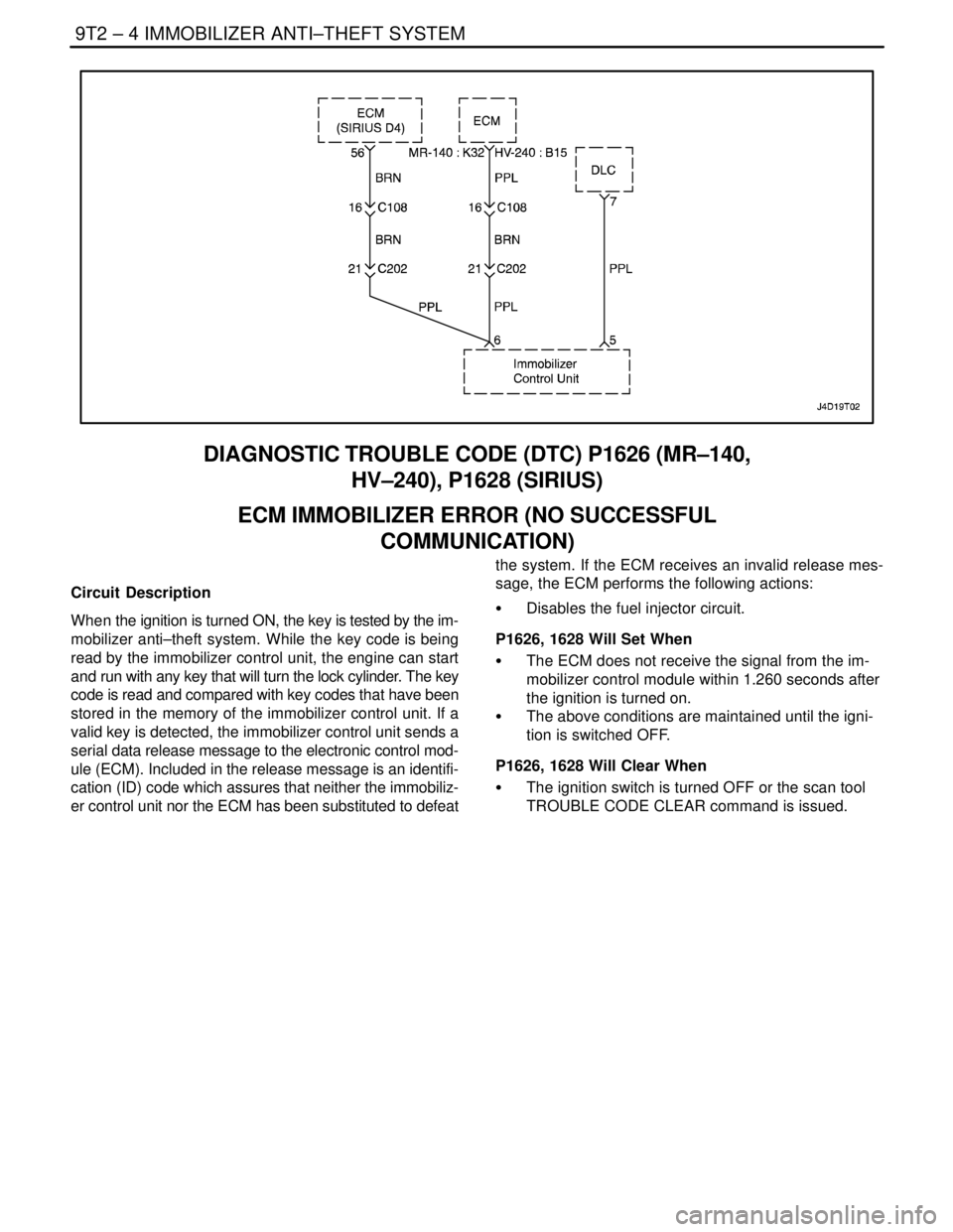
DIAGNOSTIC TROUBLE CODE (DTC) P1626 (MR–140,
HV–240), P1628 (SIRIUS)
ECM IMMOBILIZER ERROR (NO SUCCESSFUL
COMMUNICATION)
Circuit Description
When the ignition is turned ON, the key is tested by the im-
mobilizer anti–theft system. While the key code is being
read by the immobilizer control unit, the engine can start
and run with any key that will turn the lock cylinder. The key
code is read and compared with key codes that have been
stored in the memory of the immobilizer control unit. If a
valid key is detected, the immobilizer control unit sends a
serial data release message to the electronic control mod-
ule (ECM). Included in the release message is an identifi-
cation (ID) code which assures that neither the immobiliz-
er control unit nor the ECM has been substituted to defeatthe system. If the ECM receives an invalid release mes-
sage, the ECM performs the following actions:
S Disables the fuel injector circuit.
P1626, 1628 Will Set When
S The ECM does not receive the signal from the im-
mobilizer control module within 1.260 seconds after
the ignition is turned on.
S The above conditions are maintained until the igni-
tion is switched OFF.
P1626, 1628 Will Clear When
S The ignition switch is turned OFF or the scan tool
TROUBLE CODE CLEAR command is issued.
Page 2496 of 2643

9T2 – 6IIMMOBILIZER ANTI–THEFT SYSTEM
DAEWOO V–121 BL4
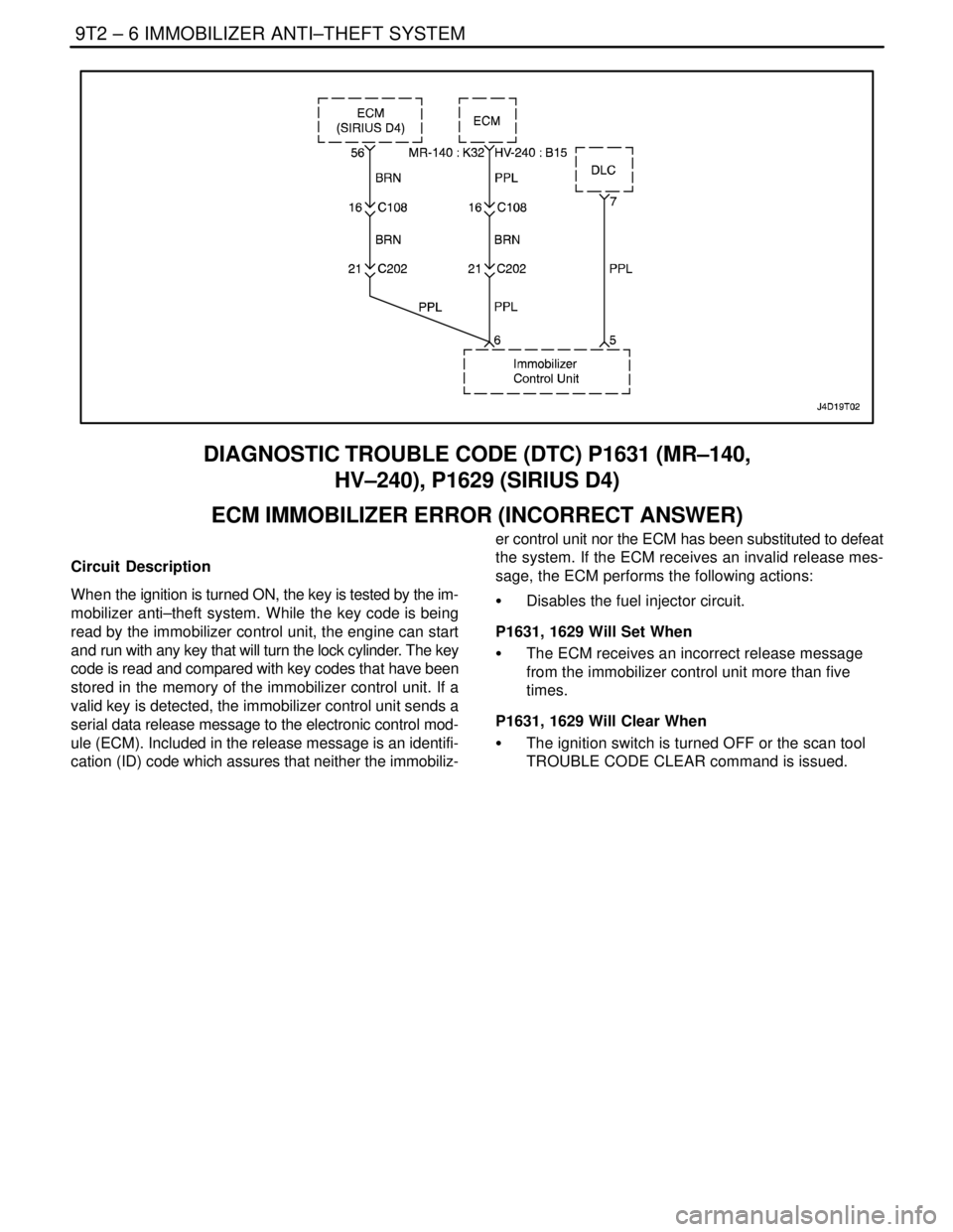
DIAGNOSTIC TROUBLE CODE (DTC) P1631 (MR–140,
HV–240), P1629 (SIRIUS D4)
ECM IMMOBILIZER ERROR (INCORRECT ANSWER)
Circuit Description
When the ignition is turned ON, the key is tested by the im-
mobilizer anti–theft system. While the key code is being
read by the immobilizer control unit, the engine can start
and run with any key that will turn the lock cylinder. The key
code is read and compared with key codes that have been
stored in the memory of the immobilizer control unit. If a
valid key is detected, the immobilizer control unit sends a
serial data release message to the electronic control mod-
ule (ECM). Included in the release message is an identifi-
cation (ID) code which assures that neither the immobiliz-er control unit nor the ECM has been substituted to defeat
the system. If the ECM receives an invalid release mes-
sage, the ECM performs the following actions:
S Disables the fuel injector circuit.
P1631, 1629 Will Set When
S The ECM receives an incorrect release message
from the immobilizer control unit more than five
times.
P1631, 1629 Will Clear When
S The ignition switch is turned OFF or the scan tool
TROUBLE CODE CLEAR command is issued.
Page 2498 of 2643

9T2 – 8IIMMOBILIZER ANTI–THEFT SYSTEM
DAEWOO V–121 BL4
KEY STATUS ERRORS (MR–140,
HV–240, SIRIUS D4)
The following KEY STATUS messages may be shown on
the scan tool after commanding FIRST KEY CODING and
KEY ADD:
S IGNITION OFF STATUS. This message informs
the technician that the ignition is off during the key
coding process. Turn the ignition ON during key
coding, but do not start the engine.
S KEY IS OCCUPIED. Only five keys may be coded.
If a new key is desired, the previous key codes
must be deleted. Up to five keys may then be au-
thorized.
S ALREADY AUTHORIZED. Key coding is being at-
tempted with a key that is already authorized.
S ERROR NO. A3, A4, A5. There is no communica-
tion between the transponder in the ignition key and
the detection coil. Follow the steps below to diag-
nose the problem:
1) Try a different key. If a different key works, the
problem was in the original key.
2) If trying a different key resulted in the same
error message, replace the detection coil.
S INVALID KEY. The communication between the
immobilizer control unit and the key transponder
has not validated the key. Follow the steps below to
diagnose the problem:
1) Code the key. Refer to ”Key Coding Procedure”
in this section.
2) If the same message is received after key cod-
ing, check the connection of the detection coil.
3) If the detection coil is okay, replace the immo-
bilizer. Refer to ”Immobilizer Control Unit” in
this section.S NO TRANSPONDER DETECTED. The fault may
be in ignition key transponder, the detection coil, or
the Immobilizer. Follow the steps below to diagnose
the problem:
1) Try a different key. If a different key works, the
problem was in the original key.
2) If trying a different key resulted in the same
error message, check the connection of the
detection coil.
3) If the connection of the detection coil is okay,
disconnect the detection coil and use an ohm-
meter to check for an open detection coil.
4) If the detection coil was not open, replace the
immobilizer control unit. Refer to ”Immobilizer
Control Unit” in this section.
COMMUNICATION BETWEEN
IMMOBILIZER CONTROL UNIT AND
TEST EQUIPMENT (MR–140, HV–240,
SIRIUS D4)
1. Connect the test equipment as described in the
Scan Tool Equipment Manual.
2. If communication between the scan tool and the
test equipment was unsuccessful, wait 30 seconds
and try again.
3. If communication was not successful on the second
try, turn the ignition OFF and check the wire and
connectors between the immobilizer control unit
terminal 7 and the data link connector (DLC) termi-
nal 7.
4. If the wire and connectors between the DLC and
the immobilizer control unit are okay, replace the
immobilizer control unit. Refer to ”Immobilizer Con-
trol Unit” in this section.
Page 2499 of 2643

IMMOBILIZER ANTI–THEFT SYSTEM 9T2 – 9
DAEWOO V–121 BL4
MAINTENANCE AND REPAIR
ON–VEHICLE SERVICE
KEY CODING PROCEDURE
1. Install the immobilizer control unit cartridge in the
scan tool.
2. Turn the ignition off
3. Connect the scan tool
4. Turn the ignition on with the key to be coded
5. Enter the four–digit password that enables service
personnel to use the scan tool for key coding.
6. Use the scan tool command.
7. Verify that the key coding was successful by start-
ing the engine with each of the authorized keys.
ID CODE REPROGRAMMING
Reprogram the identification (ID) code in the following si-
tuations:
S An immobilizer control unit has been replaced.
S An electronic control module (ECM) has been re-
placed.
If a valid key has been lost, refer to ”Key Coding Proce-
dure” in this section.
TRANSPONDER
Each valid ignition key has an internal transponder which
is a read /write transponder.
The transponder contains an implementation of a crypto–
algorithm with 96 bits of user configurable secret–key con-
tained in EEPROM and transmits data to the ICU by mod-
ulating the amplitude of the electromagnetic field, and
receives data and commands in a similar way.
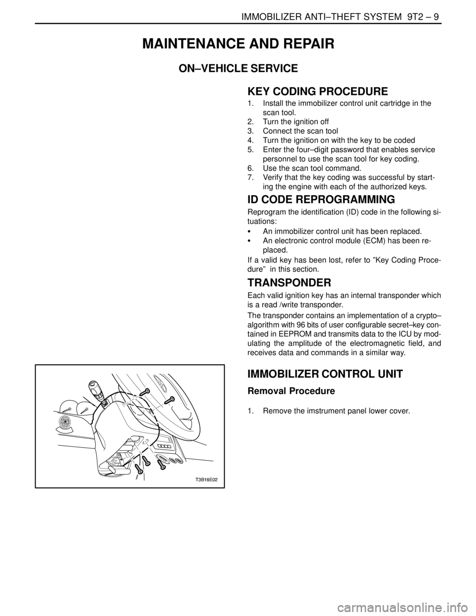
IMMOBILIZER CONTROL UNIT
Removal Procedure
1. Remove the imstrument panel lower cover.