Page 2069 of 2643

7D – 14IAUTOMATIC TEMPERATURE CONTROL HEATING, VENTILATION, AND AIR CONDITIONING SYSTEM
DAEWOO V–121 BL4
StepNo Yes Value(s) Action
20Repair the problem in circuit (Violet).
Is the repair complete?–System OK–
21Measure the resistance of circuit (Black) from termi-
nal 3 of the power transistor connector to ground.
Does the resistance match the specified value?� 0 ΩGo to Step 23Go to Step 22
221. Trace circuit (Black) from terminal 3 of the
power transistor connector and terminal 87 of
the Max HI relay to ground G203.
2. Repair any problem found in the wiring, ground
G203.
Is the repair complete?–System OK–
23Replace the ATC controller.
the repair complete?–System OK–
MODE CONTROL DO NOT WORK
Refer to ”A/C Blower and Motor Controls Diagram”for the electrical schematic diagram of the circuits described in this
procedure.
Mode Controls Do Not Work
StepActionValue(s)YesNo
1Measure the voltage between terminal 4 and termi-
nal 5 of the mode motor.
Is the voltage within the specified value for motor?11–14 vGo to Step 3Go to Step 2
21. Check fuse F7?
2. Check the connector and circuit (Brown and
Black) for any wiring or terminal problems.
3. Repair any problems found.
Is the repair complete?–System OK–
31. Using the Motor Control Table, measure the
voltages at the specified terminals of the speci-
fied motor connectors.
2. Change the mode settings and observe the
voltage changes.
Are the voltages as specified?See the ”Motor
Control Table”Go to Step 4Go to Step 5
4Replace the motor that does not operate properly.
Is the repair complete?–System OK–
51. Using the Motor Control Table, measure the
voltages at the specified terminals of the speci-
fied controller connectors.
2. Change the mode settings and observe the
voltage changes.
Are the voltages as specified?See the ”Motor
Control Table”Go to Step 6Go to Step 7
61. Check the wiring harness and connectors be-
tween the controller and the motor that is not
performing properly.
2. Repair or replace the wiring harness or the de-
fective terminal.
Is the repair complete?–System OK–
7Check the connector at the controller.
Is there a defective terminal?–Go to Step 8Go to Step 9
Page 2085 of 2643
7D – 30IAUTOMATIC TEMPERATURE CONTROL HEATING, VENTILATION, AND AIR CONDITIONING SYSTEM
DAEWOO V–121 BL4
StepNo Yes Value(s) Action
5Measure the resistance in circuit (Violet) between
terminal 6 of the power transistor and the blower mo-
tor terminal 2.
Does the resistance equal the specified value?� 0 ΩGo to Step 7Go to Step 6
6Repair or replace the wiring harness for the circuit
(Violet).
Is the repair complete?–System OK–
7Check the wiring harness of the motor and power
supply.
S Check the blower relay.
S Check fuse EF3.
Is there any problem in the wiring, the relay, or the
fuse?–Go to Step 9Go to Step 8
8Replace the power transistor.
Is the repair complete?–System OK–
9Repair or replace the wiring harness, the relay, or the
fuse as required.
Is the repair complete?–System OK–
Page 2086 of 2643
AUTOMATIC TEMPERATURE CONTROL HEATING, VENTILATION, AND AIR CONDITIONING SYSTEM 7D – 31
DAEWOO V–121 BL4
CODE 7 – MAX–HI RELAY ERROR
StepActionValue(s)YesNo
11. Turn the ignition switch ON.
2. Set the blower speed manually for maximum
speed.
3. Measure voltage between the ATC controller
terminal A10 and ground.
Is the voltage approximately equal to the specified
value?� 0 ΩGo to Step 3Go to Step 2
2Replace the ATC controller.
Is the repair complete?–System OK–
31. Check the wiring harness associated with the
MAX–HI relay for defects or high terminal re-
sistance.
2. Repair any defects found.
Is the repair complete?–System OKGo to Step 4
4Replace the MAX–HI relay.
Is the repair complete?–System OK–
Page 2088 of 2643

IAUTOMATIC TEMPERATURE CONTROL HEATING, VENTILATION, AND AIR CONDITIONING SYSTEM 7D – 33
DAEWOO V–121 BL4
SERVICEABLE COMPONENTS
COMMON HVAC COMPONENTS
Those components used in non–automatic systems are
covered in other sections of this manual.
Refer to Section 7A, Heating and Ventilation System for
the following procedures:
S Blower Motor.
S Heater Hoses.
S Blower Resistor.
S High–Blower Relay.
S Heater/Air Distributor Case Assembly (A/C Mod-
ule).
S Heater Core.
Refer to Section 7B, Manual Control Heating, Ventilation,
and Air Conditioning System, for the following proce-
dures:
S A/C Pressure Transducer.
S A/C Compressor Relay.
S Air Filter.
S A/C Expansion Valve.
S A/C High–Pressure Pipe Line.
S Evaporator Core.
S A/C Suction Hose Assembly.
S A/C Discharge Hose–Compressor to Condenser.
S Compressor.
S Condenser.
S Receiver–Dryer.
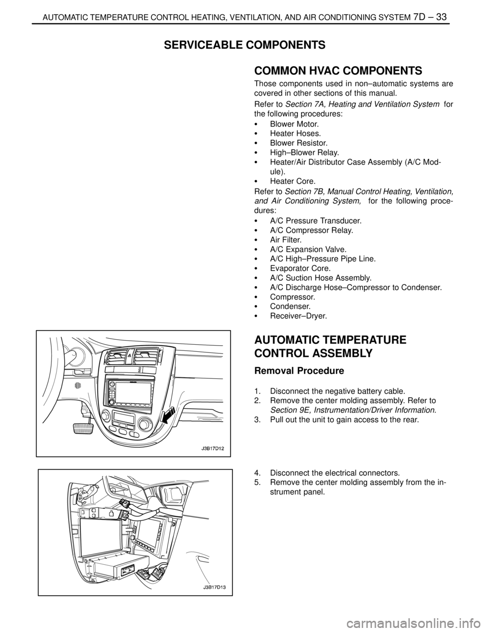
AUTOMATIC TEMPERATURE
CONTROL ASSEMBLY
Removal Procedure
1. Disconnect the negative battery cable.
2. Remove the center molding assembly. Refer to
Section 9E, Instrumentation/Driver Information.
3. Pull out the unit to gain access to the rear.
4. Disconnect the electrical connectors.
5. Remove the center molding assembly from the in-
strument panel.
Page 2089 of 2643

7D – 34IAUTOMATIC TEMPERATURE CONTROL HEATING, VENTILATION, AND AIR CONDITIONING SYSTEM
DAEWOO V–121 BL4
6. Remove the control assembly retaining screws.
7. Remove the automatic temperature control assem-
bly.
Installation Procedure
1. Position the automatic temperature control assem-
bly on the center molding and install the retaining
screws.
Tighten
Tighten the control assembly retaining screws to 2
NSm (18 lb–in).
2. Connect the electrical connectors.
3. Install the center molding assembly. Refer toSec-
tion 9E, Instrumentation/Driver Information.
4. Connect the negative battery cable.
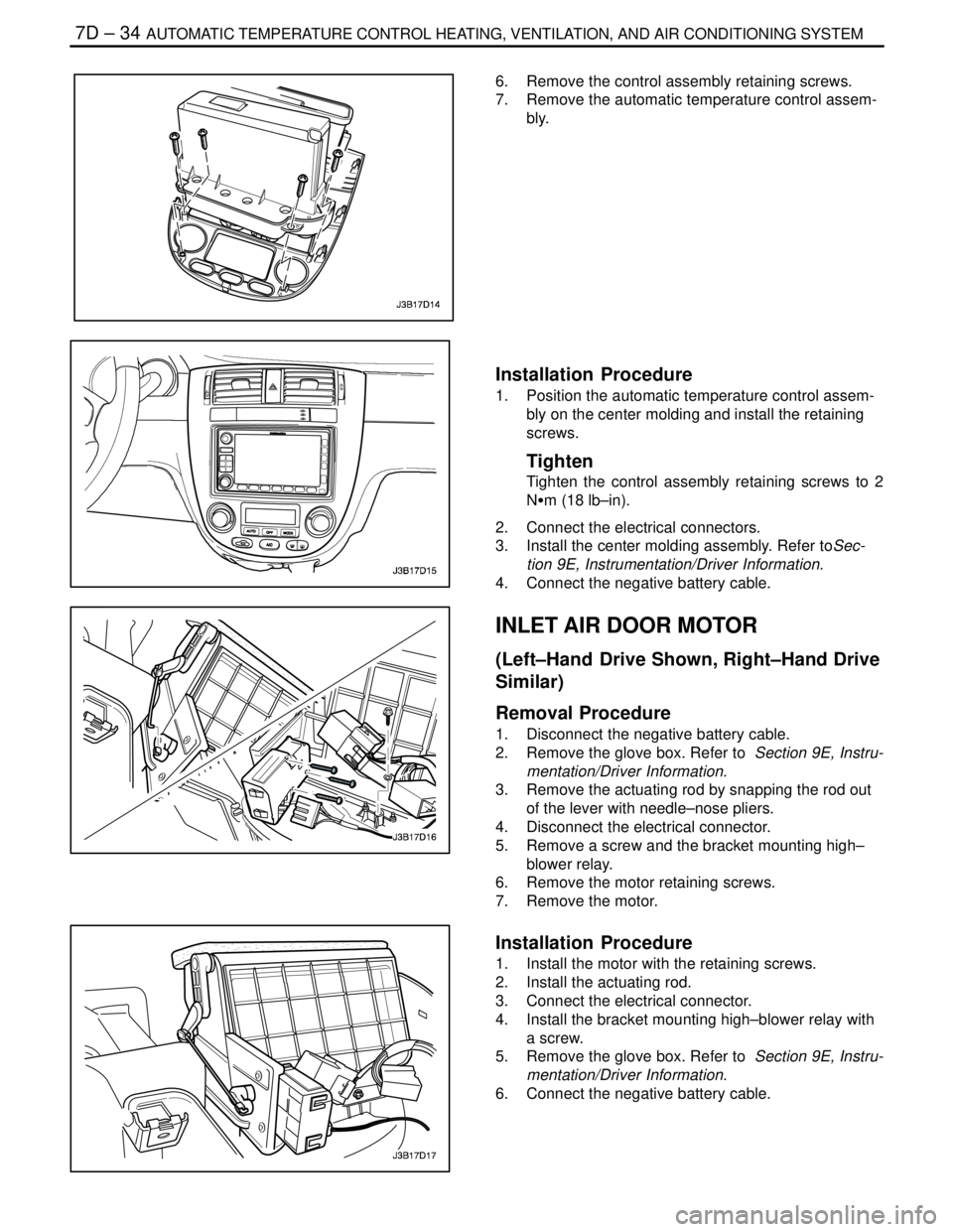
INLET AIR DOOR MOTOR
(Left–Hand Drive Shown, Right–Hand Drive
Similar)
Removal Procedure
1. Disconnect the negative battery cable.
2. Remove the glove box. Refer to Section 9E, Instru-
mentation/Driver Information.
3. Remove the actuating rod by snapping the rod out
of the lever with needle–nose pliers.
4. Disconnect the electrical connector.
5. Remove a screw and the bracket mounting high–
blower relay.
6. Remove the motor retaining screws.
7. Remove the motor.
Installation Procedure
1. Install the motor with the retaining screws.
2. Install the actuating rod.
3. Connect the electrical connector.
4. Install the bracket mounting high–blower relay with
a screw.
5. Remove the glove box. Refer to Section 9E, Instru-
mentation/Driver Information.
6. Connect the negative battery cable.
Page 2219 of 2643

BODY WIRING SYSTEM 9A – 13
DAEWOO V–121 BL4
FUSE CHART
Engine Room Fuse Block
FuseRating/SourceCircuit
EF130AB+Battery Main (F13~F16, F21~F24)
EF260AB+EBCM, Oil Feeding Connector
EF330AB+Blower Relay
EF430AB+Ignition Switch–2
EF530AB+Ignition Switch–1
EF620AB+Cooling Fan Low Relay
EF730AB+Defog Relay
EF830AB+Cooling Fan HI Relay
EF920AIGN 2Power Window Switch
EF1015AIGN 1Fuel Connector, ECM (MR–140), LEGR, EI Sys-
tem
EF1110AB+ECM, Main Relay (Sirius D4)
EF1225AB+Head Lamp Relay, ILLUM. Relay
EF1315AB+Brake Switch
EF1420AIGN 2Power Window Switch
EF1515ALightHead Lamp HI
EF1615AB+Horn Relay, Siren, Hood Contact Switch
EF1710AB+A/C Comp. Relay
EF1815AIGN 1Fuel Pump
EF1915AB+Cluster, Key Remind S/W, Folding Mirror Unit,
MAP Lamp, Room Lamp, Trunk Open Lamp,
Trunk Open S/W
EF2010ALightHead Lamp Low
EF2115AIGN 1/B+EVAP Canister Purge Solenoid, HO2S, Cooling
Fan Relay
EF2215AIGN 1/B+Injector, EGR, EEGR
EF2310AIlluminationLicense Plate Lamp, Chime Bell, Tail Lamp,
Head Lamp
EF2415AB+Fog LampRelay
EF2510AIGN 2Electric OSRV Mirror
EF2615AB+Central Door Lock Unit
EF2710ALightHead Lamp Low
EF2810AIlluminationILLUM. Circuit, Head Lamp, Tail Lamp
EF2910ASpareNot Used
EF3015ASpareNot Used
EF3125ASpareNot Used
Page 2220 of 2643
9A – 14IBODY WIRING SYSTEM
DAEWOO V–121 BL4
I/P Fuse Block
FuseRating/SourceCircuit
F110AIGN 1SDM
F210AIGN 1TCM, ECM, Generator, VGIS, VSS
F315AIGN 1Hazard Switch
F410AIGN 1Cluster, DRL Module, Chime Bell, Brake Switch,
SSPS Module, A/C Control Switch
F5–Spare–
F610AIGN 2A/C Comp. Relay, Defog Relay, Power Window
Relay, Head Lamp Relay
F720AIGN 2Blower Relay, A/C Control Switch, FATC
F815AIGN 2Electric Mirror Switch, Folding Mirror, Sun Roof
Module
F925AIGN 1Wiper Motor, Wiper Switch
F10–Spare–
F1110AIGN 1EBCM, Oil Feeding Connector
F1210AIGN 1Immobilizer, Anti Theft Control Unit, Rain Sensor
Unit
F1310AB+TCM
F1415AB+Hazard Switch
F1515AB+Anti Theft Control Unit
F1610AB+DLC
F1710AACCAudio, Clock
F1815AACCExtra Power Jack
F1915AACCCigar Lighter
F2010AIGN 1Reverse Lamp Switch, PNP Switch
F2115AB+Rear Fog Relay
F2215AB+Clock, FATC, A/C Control Switch
F2315AB+Audio
F2410AB+Immobilizer
Page 2244 of 2643

9B – 18ILIGHTING SYSTEMS
DAEWOO V–121 BL4
High–Beam and Low–Beam Headlamps Are Inoperative On Both
Left and Right Sides
StepActionValue(s)YesNo
1Check fuses F6, Ef2, Ef20, Ef27 and Ef15.
Is any fuse blown?–Go to Step 2Go to Step 3
21. Check for a short circuit and repair if neces-
sary.
2. Replace the fuse.
Is the repair complete?–System OK–
31. Turn the low–beam headlamps ON.
2. Check the voltage at fuses Ef20, Ef27 and
Ef15.
Does the voltage at the headlamps equal the value
specified?11–14 vGo to Step 4Go to Step 9
41. Turn the low–beam headlamps ON.
2. Check the voltage at the headlamp connector
terminal 5.
3. Turn the high–beam headlamps ON.
4. Check the voltage at headlamp connector ter-
minal 4.
Does the battery voltage available at the headlamps
equal the value specified?11–14 vGo to Step 6Go to Step 5
5Repair the open circuit between fuses Ef20, Ef27
and Ef15 and the headlamps.
Is the repair complete?–System OK–
6Use an ohmmeter to check between ground and
each headlamp connector terminal 6.
Is the resistance equal to the specified value?0 WGo to Step 8Go to Step 7
7Repair the ground circuit.
Is the repair complete?–System OK–
81. Replace the faulty headlamps.
2. Check the charging system to make sure that
charging voltage is not excessively high. Re-
pair if necessary.
Is the repair complete?–System OK–
9Temporarily substitute the illumination relay in place
of the headlamp relay.
Do the headlamps operate with the substituted
relay?–Go to Step 10Go to Step 11
10Install the illumination relay in its original position,
and install a new headlamp relay.
Is the repair complete?–System OK–
111. With the headlamp relay removed, turn the
headlamp switch to the low–beam position.
2. Use an ohmmeter to check the continuity be-
tween the connector for relay terminal 85 and
ground.
Does the ohmmeter indicate the specified value?� 0 WGo to Step 17Go to Step 12