2004 DAEWOO LACETTI engin control
[x] Cancel search: engin controlPage 5 of 2643

v
TABLE OF CONTENTS
Section 0B General Information
Section 1 Engine
Section 1A General Engine Information
Section 1C1 1.4L/1.6L DOHC Engine Mechanical
Section 1C2 1.8L DOHC Engine Mechanical
Section 1D Engine Cooling
Section 1E Engine Electrical
Section 1F Engine Controls
Section 1G Engine Exhaust
Section 2 Suspension
Section 2A Suspension Diagnosis
Section 2B Wheel Alignment
Section 2C Front Suspension
Section 2D Rear Suspension
Section 2E Tires and Wheels
Section 3 Driveline/Axle
Section 3A Automatic Transaxle Drive Axle
Section 3B Manual Transaxle Drive Axle
Section 4 Brakes
Section 4A Hydraulic Brakes
Section 4B Master Cylinder
Section 4C Power Booster
Section 4D Front Disc Brakes
Section 4E1 Rear Disc Brakes
Section 4E2 Rear Drum Brakes
Section 4F Antilock Brake System
Section 4G Parking Brake
Section 5 Transmission/Transaxle
Section 5A1 ZF 4HP16 Automatic Transaxle
Section 5A2 AISIN Automatic Transaxle
Section 5B Five-Speed Manual Transaxle
Section 5C Clutch
Section 6 Steering
Section 6A Power Steering System
Section 6B Power Steering PumpSection 6C Power Steering Gear
Section 6E Steering Wheel and Column
Section 7 Heating, Ventilation, and Air
Conditioning (HVAC)
Section 7A Heating and Ventilation System
Section 7B Manual Control Heating, Ventilation,
and Air Conditioning System
Section 7D Automatic Temperature Control HVAC
Section 8 Restraints
Section 8A Seat Belts
Section 8B Supplemental Inflatable Restraints
(SIR)
Section 9 Body and Accessories
Section 9A Body Wiring System
Section 9B Lighting Systems
Section 9C Horns
Section 9D Wipers/Washer Systems
Section 9E Instrumentation/Driver Information
Section 9F Audio Systems
Section 9G Interior Trim
Section 9H Seats
Section 9I Waterleaks
Section 9J Windnoise
Section 9K Squeaks and Rattles
Section 9L Glass and Mirrors
Section 9M Exterior Trim
Section 9N Frame and Underbody
Section 9O Bumpers and Fascias
Section 9P Doors
Section 9Q Roof
Section 9R Body Front End
Section 9S Body Rear End
Section 9T1 Remote Keyless Entry and Anti–Theft
System
Section 9T2 Immobilizer Anti–Theft System
Page 20 of 2643

GENERAL INFORMATION 0B – 13
DAEWOO V–121 BL4
EACH TIME THE OIL IS CHANGED
Automatic Transaxle Fluid
Refer to fluid level service procedure of Section 5A, ZF
4HP16 Automatic Transaxle.
Manual Transaxle
Check the fluid level and add fluid as required. Refer to
Section 5B, Five–Speed Manual Transaxle.
Brake System Inspection
This inspection should be done when the wheels are re-
moved for rotation. Inspect the lines and the hoses for
proper hookup, binding, leaks, cracks, chafing, etc. In-
spect the disc brake pads for wear. Inspect the rotors for
surface condition. Also inspect the drum brake linings for
wear and cracks. Inspect other brake parts, including the
drums, the wheels cylinders, the parking brake, etc., at the
same time. Check the parking brake adjustment. Inspect
the brakes more often if habit or conditions result in fre-
quent braking.
Steering, Suspension and Front Drive Axle
Boot And Seal Inspection
Inspect the front and rear suspension and the steering
system for damaged, loose or missing parts, signs of wear
or lack of lubrication. Inspect the power steering lines and
the hoses for proper hookup, binding, leaks, cracks, chaf-
ing, etc. Clean and inspect the drive axle boot and seals
for damage, tears or leakage. Replace the seals if neces-
sary.
Exhaust System Inspection
Inspect the complete system (including the catalytic con-
verter if equipped). Inspect the body near the exhaust sys-
tem. Look for broken, damaged, missing, or out–of–posi-
tion parts as well as open seams, holes, loose
connections, or other conditions which could cause heat
buildup in the floor pan or could let exhaust fumes seep
into the trunk or passenger compartment.
Throttle Linkage Inspection
Inspect the throttle linkage for interference or binding,
damaged, or missing parts. Lubricate all linkage joints and
throttle cable joints, the intermediate throttle shaft bearing,
the return spring at throttle valve assembly, and the accel-
erator pedal sliding face with suitable grease. Check the
throttle cable for free movements.
Engine Drive Belts
Inspect all belts for cracks, fraying, wear and proper ten-
sion. Adjust or replace the belts as needed.
Hood Latch Operation
When opening the hood, note the operation of the secon-
dary latch. It should keep the hood from opening all the
way when the primary latch is released. The hood must
close firmly.
AT LEAST ANNUALLY
Lap and Shoulder Belts Condition and
Operation
Inspect the belt system including: the webbing, the
buckles, the latch plates, the retractor, the guide loops and
the anchors.
Movable Head Restraint Operation
On vehicles with movable head restraints, the restraints
must stay in the desired position.
Spare Tire and Jack Storage
Be alert to rattles in the rear of the vehicle. The spare tire,
all the jacking equipment, and the tools must be securely
stowed at all times. Oil the jack ratchet or the screw mech-
anism after each use.
Key Lock Service
Lubricate the key lock cylinder.
Body Lubrication Service
Lubricate all the body door hinges including the hood, the
fuel door, the rear compartment hinges and the latches,
the glove box and the console doors, and any folding seat
hardware.
Transaxle Neutral Switch Operation on
Automatic Transaxle
CAUTION : Take the following precautions because
the vehicle could move without warning and possibly
cause personal injury or property damage:
S Firmly apply the parking brake and the regular
brakes.
S Do not use the accelerator pedal.
S Be ready to promptly turn off the ignition if the ve-
hicle starts.
On automatic transaxle vehicles, try to start the engine in
each gear. The starter should crank only in P (Park) or N
(Neutral).
Parking Brake and Transaxle P (Park)
Mechanism Operation
CAUTION : In order to reduce the risk of personal in-
jury or property damage, be prepared to apply the reg-
ular brakes promptly if the vehicle begins to move.
Park on a fairly steep hill with enough room for movement
in the downhill direction. To check the parking brake, with
the engine running and the transaxle in N (Neutral), slowly
remove foot pressure from the regular brake pedal (until
only the parking brake is holding the vehicle).
To check the automatic transaxle P (Park) mechanism’s
holding ability, release all brakes after shifting the trans-
axle to P (Park).
Underbody Flushing
Flushing the underbody will remove any corrosive materi-
als used for ice and snow removal and dust control. At
least every spring clean the underbody. First, loosen the
sediment packed in closed areas of the vehicle. Then flush
the underbody with plain water.
Page 59 of 2643
1C1 – 16I1.4L/1.6L DOHC ENGINE MECHANICAL
DAEWOO V–121 BL4
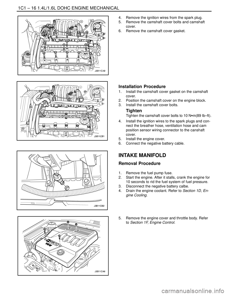
4. Remove the ignition wires from the spark plug.
5. Remove the camshaft cover bolts and camshaft
cover.
6. Remove the camshaft cover gasket.
Installation Procedure
1. Install the camshaft cover gasket on the camshaft
cover.
2. Position the camshaft cover on the engine block.
3. Install the camshaft cover bolts.
Tighten
Tighten the camshaft cover bolts to 10 NSm(89 lb–ft).
4. Install the ignition wires to the spark plugs and con-
nect the breather hose, ventilation hose and cam
position sensor wiring connector to the canshaft
cover.
5. Install the engine cover.
6. Connect the negative battery cable.
INTAKE MANIFOLD
Removal Procedure
1. Remove the fuel pump fuse.
2. Start the engine. After it stalls, crank the engine for
10 seconds to rid the fuel system of fuel pressure.
3. Disconnect the negative battery calbe.
4. Drain the engine coolant. Refer to Section 1D, En-
gine Cooling.
5. Remove the engine cover and throttle body. Refer
to Section 1F, Engine Control.
Page 64 of 2643
1.4L/1.6L DOHC ENGINE MECHANICAL 1C1 – 21
DAEWOO V–121 BL4
Installation Procedure
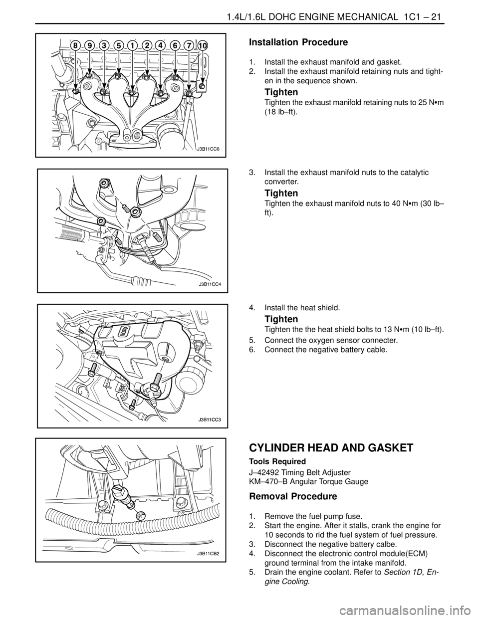
1. Install the exhaust manifold and gasket.
2. Install the exhaust manifold retaining nuts and tight-
en in the sequence shown.
Tighten
Tighten the exhaust manifold retaining nuts to 25 NSm
(18 lb–ft).
3. Install the exhaust manifold nuts to the catalytic
converter.
Tighten
Tighten the exhaust manifold nuts to 40 NSm (30 lb–
ft).
4. Install the heat shield.
Tighten
Tighten the the heat shield bolts to 13 NSm (10 lb–ft).
5. Connect the oxygen sensor connecter.
6. Connect the negative battery cable.
CYLINDER HEAD AND GASKET
Tools Required
J–42492 Timing Belt Adjuster
KM–470–B Angular Torque Gauge
Removal Procedure
1. Remove the fuel pump fuse.
2. Start the engine. After it stalls, crank the engine for
10 seconds to rid the fuel system of fuel pressure.
3. Disconnect the negative battery calbe.
4. Disconnect the electronic control module(ECM)
ground terminal from the intake manifold.
5. Drain the engine coolant. Refer to Section 1D, En-
gine Cooling.
Page 91 of 2643
1C1 – 48I1.4L/1.6L DOHC ENGINE MECHANICAL
DAEWOO V–121 BL4
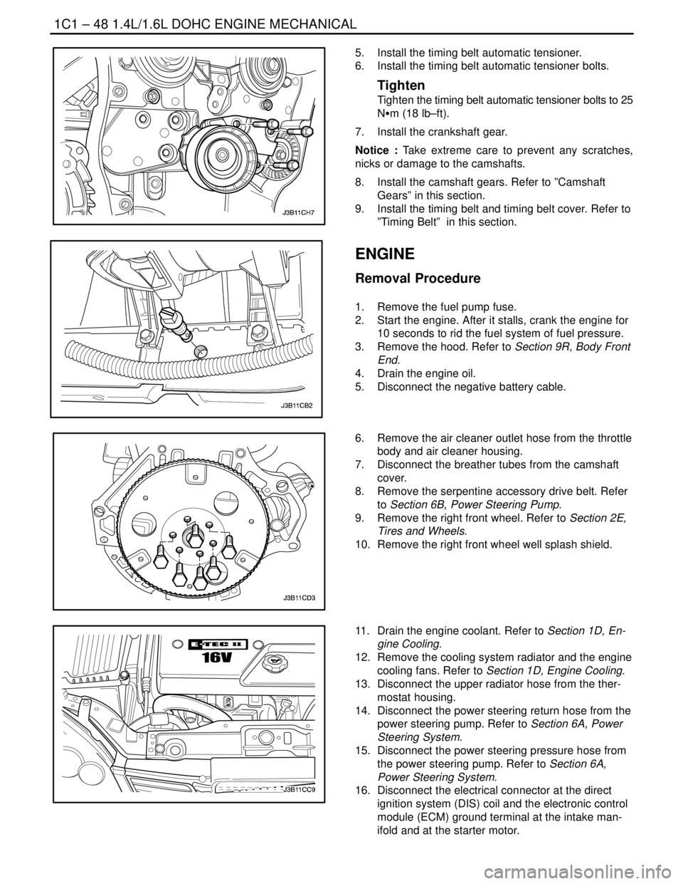
5. Install the timing belt automatic tensioner.
6. Install the timing belt automatic tensioner bolts.
Tighten
Tighten the timing belt automatic tensioner bolts to 25
NSm (18 lb–ft).
7. Install the crankshaft gear.
Notice : Take extreme care to prevent any scratches,
nicks or damage to the camshafts.
8. Install the camshaft gears. Refer to ”Camshaft
Gears” in this section.
9. Install the timing belt and timing belt cover. Refer to
”Timing Belt” in this section.
ENGINE
Removal Procedure
1. Remove the fuel pump fuse.
2. Start the engine. After it stalls, crank the engine for
10 seconds to rid the fuel system of fuel pressure.
3. Remove the hood. Refer to Section 9R, Body Front
End.
4. Drain the engine oil.
5. Disconnect the negative battery cable.
6. Remove the air cleaner outlet hose from the throttle
body and air cleaner housing.
7. Disconnect the breather tubes from the camshaft
cover.
8. Remove the serpentine accessory drive belt. Refer
to Section 6B, Power Steering Pump.
9. Remove the right front wheel. Refer to Section 2E,
Tires and Wheels.
10. Remove the right front wheel well splash shield.
11. Drain the engine coolant. Refer to Section 1D, En-
gine Cooling.
12. Remove the cooling system radiator and the engine
cooling fans. Refer to Section 1D, Engine Cooling.
13. Disconnect the upper radiator hose from the ther-
mostat housing.
14. Disconnect the power steering return hose from the
power steering pump. Refer to Section 6A, Power
Steering System.
15. Disconnect the power steering pressure hose from
the power steering pump. Refer to Section 6A,
Power Steering System.
16. Disconnect the electrical connector at the direct
ignition system (DIS) coil and the electronic control
module (ECM) ground terminal at the intake man-
ifold and at the starter motor.
Page 92 of 2643

1.4L/1.6L DOHC ENGINE MECHANICAL 1C1 – 49
DAEWOO V–121 BL4
17. Disconnect the oxygen (O2) sensor connector, if
equipped.
18. Disconnect the fuel injector harness connectors.
19. Disconnect the MAT, MAP sensor connectors.
20. Disconnect the throttle position sensor (TPS) con-
nector.
21. Disconnect the generator voltage regulator connec-
tor and power lead.
22. Remove the electrical harness clamp bolt.
23. Disconnect all of the necessary vacuum lines, in-
cluding the brake booster vacuum hose.
24. Disconnect the fuel feed line at the fuel rail.
25. Disconnect the throttle cable from the throttle body
and the intake manifold bracket.
26. Disconnect the surge tank coolant hose at the
throttle body.
27. Disconnect the heater outlet hose at the coolant
pipe.
28. Disconnect the heater inlet hose from the cylinder
head.
29. Disconnect the surge tank coolant hose from the
coolant pipe.
30. Disconnect the lower radiator hose from the coolant
pipe. Disconnect the starter solenoid ”S” terminal
wire. Remove the A/C compressor, if equipped. Re-
fer to Section 7B, Manual Control Heating, Ventila-
tion, and Air Conditioning Systems.
31. Remove the catalytic converter retaining nuts from
the exhaust pipe.
32. Remove the exhaust pipe.
Page 95 of 2643

1C1 – 52I1.4L/1.6L DOHC ENGINE MECHANICAL
DAEWOO V–121 BL4
18. Connect the power steering pressure hose.
19. Connect the power steering return hose.
20. Install the A/C compressor, if equipped. Refer to
Section 7B, Manual Control Heating, Ventilation,
and Air Conditioning Systems.
21. Install the generator. Refer to Section 1E, Engine
Electrical.
22. Install the serpentine accessory drive belt. Refer to
Section 6B, Power Steering Pump.
23. Install the right front wheel well splash shield.
24. Install the right front wheel. Refer to Section 2E,
Tires and Wheels.
25. Connect the fuel feed line to the fuel rail.
26. Connect all of the necessary vacuum lines, includ-
ing the brake booster vacuum hose.
27. Connect the O2 sensor connector, if equipped.
28. Connect the starter solenoid ”S” terminal wire and
power lead.
29. Connect the generator voltage regulator connector
and power lead.
30. Connect the CTS connector.
31. Connect the MAP, MAT sensor connectors.
32. Connect the TPS connector.
33. Install the electrical wiring harness clamp at the
intake manifold support bracket.
34. Connect the fuel injector harness connectors.
35. Connect the electrical connector at the DIS coil and
the ECM ground terminal at the starter.
36. Install the air cleaner outlet hose between the
throttle body and the air cleaner housing.
37. Connect the breather tubes to the camshaft cover.
38. Install the cooling system radiator and the engine
cooling fans. Refer to Section 1D, Engine Cooling.
Page 96 of 2643
1.4L/1.6L DOHC ENGINE MECHANICAL 1C1 – 53
DAEWOO V–121 BL4
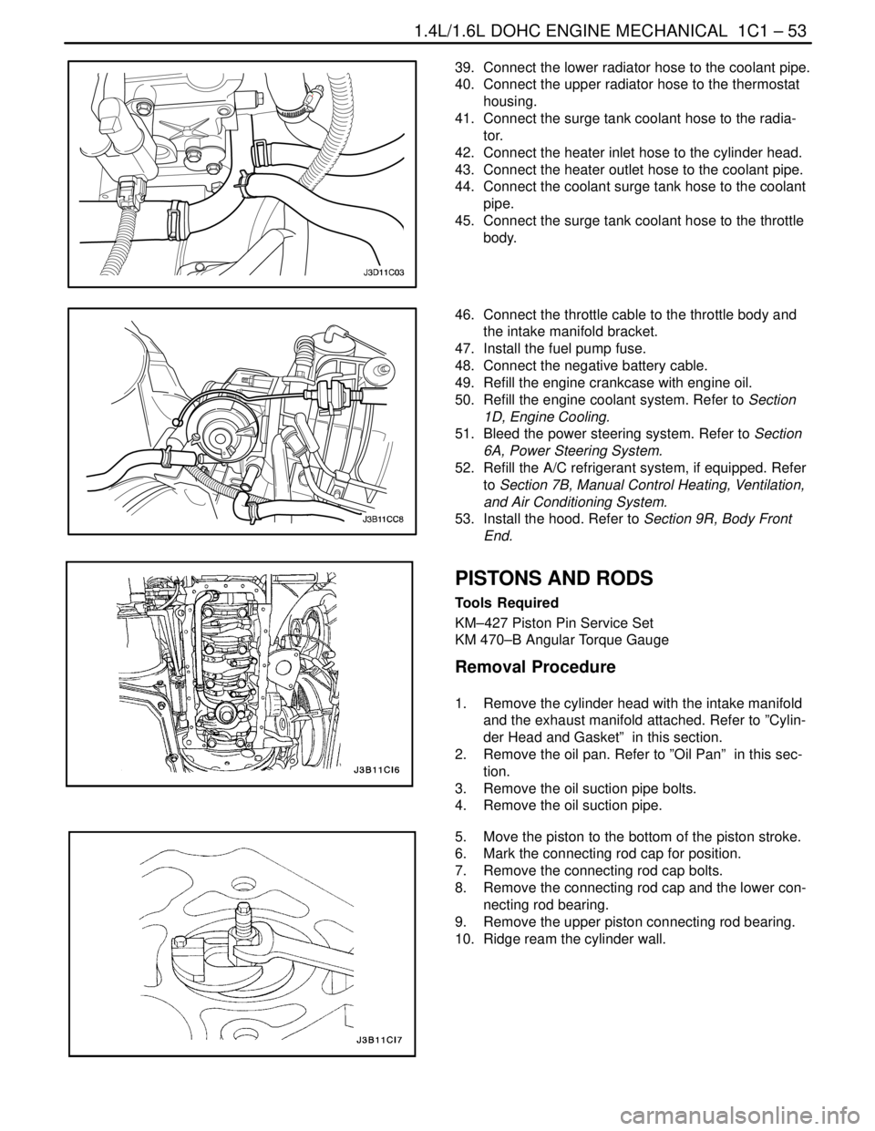
39. Connect the lower radiator hose to the coolant pipe.
40. Connect the upper radiator hose to the thermostat
housing.
41. Connect the surge tank coolant hose to the radia-
tor.
42. Connect the heater inlet hose to the cylinder head.
43. Connect the heater outlet hose to the coolant pipe.
44. Connect the coolant surge tank hose to the coolant
pipe.
45. Connect the surge tank coolant hose to the throttle
body.
46. Connect the throttle cable to the throttle body and
the intake manifold bracket.
47. Install the fuel pump fuse.
48. Connect the negative battery cable.
49. Refill the engine crankcase with engine oil.
50. Refill the engine coolant system. Refer to Section
1D, Engine Cooling.
51. Bleed the power steering system. Refer to Section
6A, Power Steering System.
52. Refill the A/C refrigerant system, if equipped. Refer
to Section 7B, Manual Control Heating, Ventilation,
and Air Conditioning System.
53. Install the hood. Refer to Section 9R, Body Front
End.
PISTONS AND RODS
Tools Required
KM–427 Piston Pin Service Set
KM 470–B Angular Torque Gauge
Removal Procedure
1. Remove the cylinder head with the intake manifold
and the exhaust manifold attached. Refer to ”Cylin-
der Head and Gasket” in this section.
2. Remove the oil pan. Refer to ”Oil Pan” in this sec-
tion.
3. Remove the oil suction pipe bolts.
4. Remove the oil suction pipe.
5. Move the piston to the bottom of the piston stroke.
6. Mark the connecting rod cap for position.
7. Remove the connecting rod cap bolts.
8. Remove the connecting rod cap and the lower con-
necting rod bearing.
9. Remove the upper piston connecting rod bearing.
10. Ridge ream the cylinder wall.