2004 DAEWOO LACETTI Steering pump removal procedure
[x] Cancel search: Steering pump removal procedurePage 77 of 2643
1C1 – 34I1.4L/1.6L DOHC ENGINE MECHANICAL
DAEWOO V–121 BL4
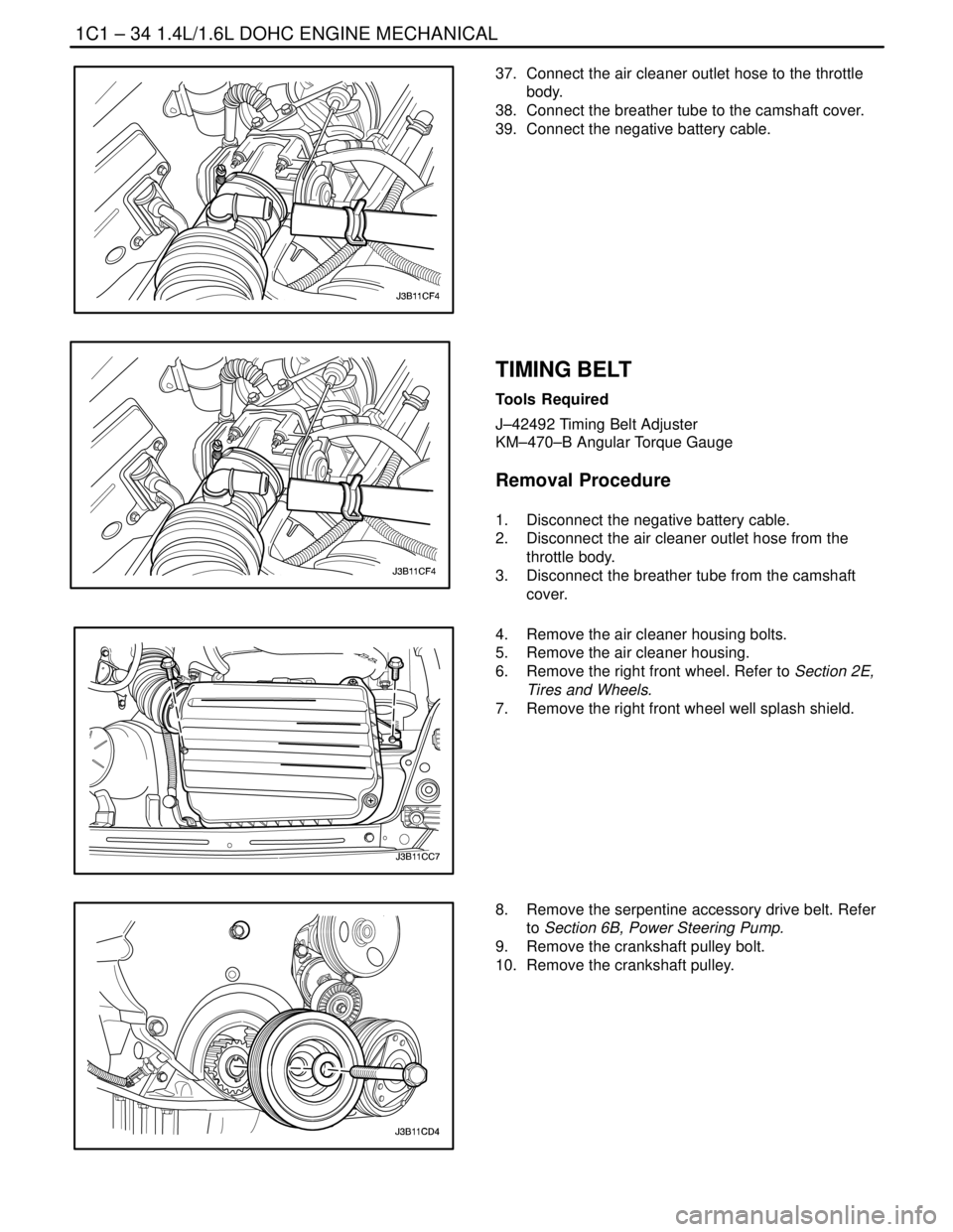
37. Connect the air cleaner outlet hose to the throttle
body.
38. Connect the breather tube to the camshaft cover.
39. Connect the negative battery cable.
TIMING BELT
Tools Required
J–42492 Timing Belt Adjuster
KM–470–B Angular Torque Gauge
Removal Procedure
1. Disconnect the negative battery cable.
2. Disconnect the air cleaner outlet hose from the
throttle body.
3. Disconnect the breather tube from the camshaft
cover.
4. Remove the air cleaner housing bolts.
5. Remove the air cleaner housing.
6. Remove the right front wheel. Refer to Section 2E,
Tires and Wheels.
7. Remove the right front wheel well splash shield.
8. Remove the serpentine accessory drive belt. Refer
to Section 6B, Power Steering Pump.
9. Remove the crankshaft pulley bolt.
10. Remove the crankshaft pulley.
Page 83 of 2643
1C1 – 40I1.4L/1.6L DOHC ENGINE MECHANICAL
DAEWOO V–121 BL4
OIL PUMP
Tools Required
KM–498–B Pressure Gauge
KM–135 Adapter
Engine Oil Pressure Inspection Procedure
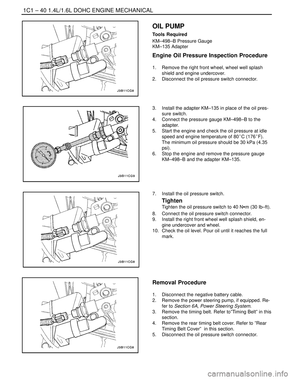
1. Remove the right front wheel, wheel well splash
shield and engine undercover.
2. Disconnect the oil pressure switch connector.
3. Install the adapter KM–135 in place of the oil pres-
sure switch.
4. Connect the pressure gauge KM–498–B to the
adapter.
5. Start the engine and check the oil pressure at idle
speed and engine temperature of 80°C (176°F).
The minimum oil pressure should be 30 kPa (4.35
psi).
6. Stop the engine and remove the pressure gauge
KM–498–B and the adapter KM–135.
7. Install the oil pressure switch.
Tighten
Tighten the oil pressure switch to 40 NSm (30 lb–ft).
8. Connect the oil pressure switch connector.
9. Install the right front wheel well splash shield, en-
gine undercover and wheel.
10. Check the oil level. Pour oil until it reaches the full
mark.
Removal Procedure
1. Disconnect the negative battery cable.
2. Remove the power steering pump, if equipped. Re-
fer to Section 6A, Power Steering System.
3. Remove the timing belt. Refer to”Timing Belt” in this
section.
4. Remove the rear timing belt cover. Refer to ”Rear
Timing Belt Cover” in this section.
5. Disconnect the oil pressure switch connector.
Page 86 of 2643
1.4L/1.6L DOHC ENGINE MECHANICAL 1C1 – 43
DAEWOO V–121 BL4
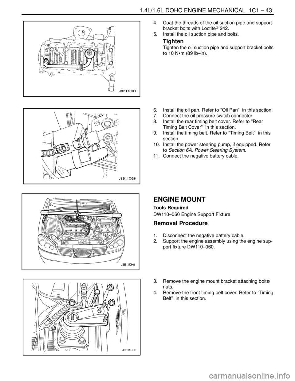
4. Coat the threads of the oil suction pipe and support
bracket bolts with Loctite® 242.
5. Install the oil suction pipe and bolts.
Tighten
Tighten the oil suction pipe and support bracket bolts
to 10 NSm (89 lb–in).
6. Install the oil pan. Refer to ”Oil Pan” in this section.
7. Connect the oil pressure switch connector.
8. Install the rear timing belt cover. Refer to ”Rear
Timing Belt Cover” in this section.
9. Install the timing belt. Refer to ”Timing Belt” in this
section.
10. Install the power steering pump, if equipped. Refer
to Section 6A, Power Steering System.
11. Connect the negative battery cable.
ENGINE MOUNT
Tools Required
DW110–060 Engine Support Fixture
Removal Procedure
1. Disconnect the negative battery cable.
2. Support the engine assembly using the engine sup-
port fixture DW110–060.
3. Remove the engine mount bracket attaching bolts/
nuts.
4. Remove the front timing belt cover. Refer to ”Timing
Belt” in this section.
Page 91 of 2643
1C1 – 48I1.4L/1.6L DOHC ENGINE MECHANICAL
DAEWOO V–121 BL4
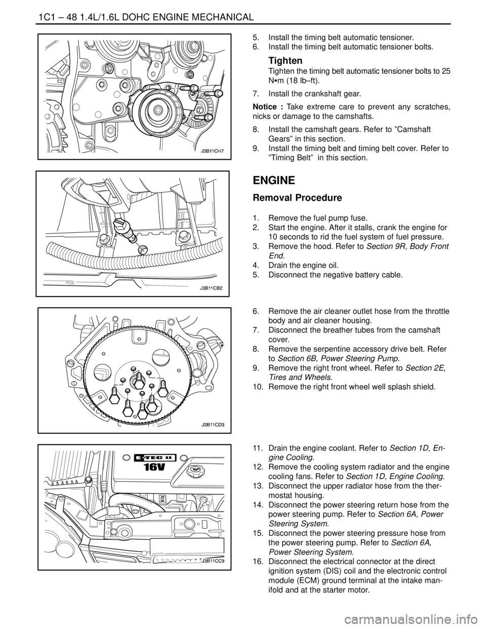
5. Install the timing belt automatic tensioner.
6. Install the timing belt automatic tensioner bolts.
Tighten
Tighten the timing belt automatic tensioner bolts to 25
NSm (18 lb–ft).
7. Install the crankshaft gear.
Notice : Take extreme care to prevent any scratches,
nicks or damage to the camshafts.
8. Install the camshaft gears. Refer to ”Camshaft
Gears” in this section.
9. Install the timing belt and timing belt cover. Refer to
”Timing Belt” in this section.
ENGINE
Removal Procedure
1. Remove the fuel pump fuse.
2. Start the engine. After it stalls, crank the engine for
10 seconds to rid the fuel system of fuel pressure.
3. Remove the hood. Refer to Section 9R, Body Front
End.
4. Drain the engine oil.
5. Disconnect the negative battery cable.
6. Remove the air cleaner outlet hose from the throttle
body and air cleaner housing.
7. Disconnect the breather tubes from the camshaft
cover.
8. Remove the serpentine accessory drive belt. Refer
to Section 6B, Power Steering Pump.
9. Remove the right front wheel. Refer to Section 2E,
Tires and Wheels.
10. Remove the right front wheel well splash shield.
11. Drain the engine coolant. Refer to Section 1D, En-
gine Cooling.
12. Remove the cooling system radiator and the engine
cooling fans. Refer to Section 1D, Engine Cooling.
13. Disconnect the upper radiator hose from the ther-
mostat housing.
14. Disconnect the power steering return hose from the
power steering pump. Refer to Section 6A, Power
Steering System.
15. Disconnect the power steering pressure hose from
the power steering pump. Refer to Section 6A,
Power Steering System.
16. Disconnect the electrical connector at the direct
ignition system (DIS) coil and the electronic control
module (ECM) ground terminal at the intake man-
ifold and at the starter motor.
Page 96 of 2643
1.4L/1.6L DOHC ENGINE MECHANICAL 1C1 – 53
DAEWOO V–121 BL4
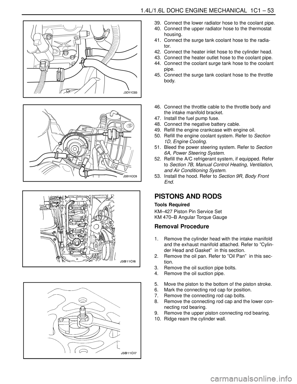
39. Connect the lower radiator hose to the coolant pipe.
40. Connect the upper radiator hose to the thermostat
housing.
41. Connect the surge tank coolant hose to the radia-
tor.
42. Connect the heater inlet hose to the cylinder head.
43. Connect the heater outlet hose to the coolant pipe.
44. Connect the coolant surge tank hose to the coolant
pipe.
45. Connect the surge tank coolant hose to the throttle
body.
46. Connect the throttle cable to the throttle body and
the intake manifold bracket.
47. Install the fuel pump fuse.
48. Connect the negative battery cable.
49. Refill the engine crankcase with engine oil.
50. Refill the engine coolant system. Refer to Section
1D, Engine Cooling.
51. Bleed the power steering system. Refer to Section
6A, Power Steering System.
52. Refill the A/C refrigerant system, if equipped. Refer
to Section 7B, Manual Control Heating, Ventilation,
and Air Conditioning System.
53. Install the hood. Refer to Section 9R, Body Front
End.
PISTONS AND RODS
Tools Required
KM–427 Piston Pin Service Set
KM 470–B Angular Torque Gauge
Removal Procedure
1. Remove the cylinder head with the intake manifold
and the exhaust manifold attached. Refer to ”Cylin-
der Head and Gasket” in this section.
2. Remove the oil pan. Refer to ”Oil Pan” in this sec-
tion.
3. Remove the oil suction pipe bolts.
4. Remove the oil suction pipe.
5. Move the piston to the bottom of the piston stroke.
6. Mark the connecting rod cap for position.
7. Remove the connecting rod cap bolts.
8. Remove the connecting rod cap and the lower con-
necting rod bearing.
9. Remove the upper piston connecting rod bearing.
10. Ridge ream the cylinder wall.
Page 148 of 2643

1C2 – 28I1.8L DOHC ENGINE MECHANICAL
DAEWOO V–121 BL4
TIMING BELT
Removal Procedure
1. Disconnect the negative battery cable.
2. Disconnect the manifold air temperature (MAT)
sensor connector.
3. Disconnect the air cleaner outlet hose from the
throttle body.
4. Disconnect the breather tube from the camshaft
cover.
5. Remove the air cleaner housing bolts.
6. Remove the air cleaner housing.
7. Remove the right front wheel. Refer to Section 2E,
Tires and Wheels.
8. Remove the right front wheel well splash shield.
9. Remove the serpentine accessory drive belt. Refer
to Section 6B, Power Steering Pump.
10. Remove the crankshaft pulley bolts.
11. Remove the crankshaft pulley.
12. Remove the right engine mount bracket. Refer to
”Engine Mount” in this section.
13. Remove the front timing belt cover bolts.
14. Remove the front timing belt cover.
Page 157 of 2643
1.8L DOHC ENGINE MECHANICAL 1C2 – 37
DAEWOO V–121 BL4
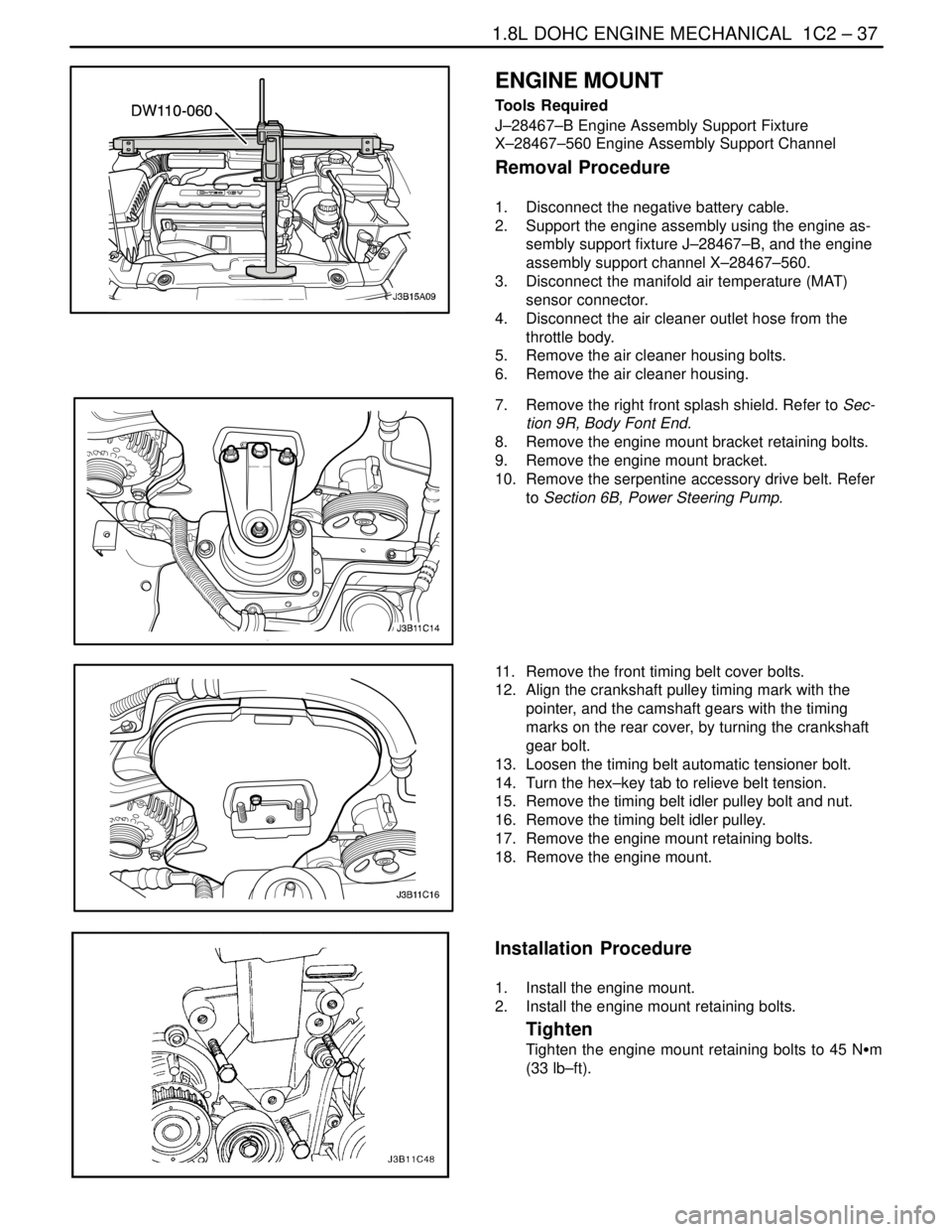
ENGINE MOUNT
Tools Required
J–28467–B Engine Assembly Support Fixture
X–28467–560 Engine Assembly Support Channel
Removal Procedure
1. Disconnect the negative battery cable.
2. Support the engine assembly using the engine as-
sembly support fixture J–28467–B, and the engine
assembly support channel X–28467–560.
3. Disconnect the manifold air temperature (MAT)
sensor connector.
4. Disconnect the air cleaner outlet hose from the
throttle body.
5. Remove the air cleaner housing bolts.
6. Remove the air cleaner housing.
7. Remove the right front splash shield. Refer to Sec-
tion 9R, Body Font End.
8. Remove the engine mount bracket retaining bolts.
9. Remove the engine mount bracket.
10. Remove the serpentine accessory drive belt. Refer
to Section 6B, Power Steering Pump.
11. Remove the front timing belt cover bolts.
12. Align the crankshaft pulley timing mark with the
pointer, and the camshaft gears with the timing
marks on the rear cover, by turning the crankshaft
gear bolt.
13. Loosen the timing belt automatic tensioner bolt.
14. Turn the hex–key tab to relieve belt tension.
15. Remove the timing belt idler pulley bolt and nut.
16. Remove the timing belt idler pulley.
17. Remove the engine mount retaining bolts.
18. Remove the engine mount.
Installation Procedure
1. Install the engine mount.
2. Install the engine mount retaining bolts.
Tighten
Tighten the engine mount retaining bolts to 45 NSm
(33 lb–ft).
Page 158 of 2643
1C2 – 38I1.8L DOHC ENGINE MECHANICAL
DAEWOO V–121 BL4
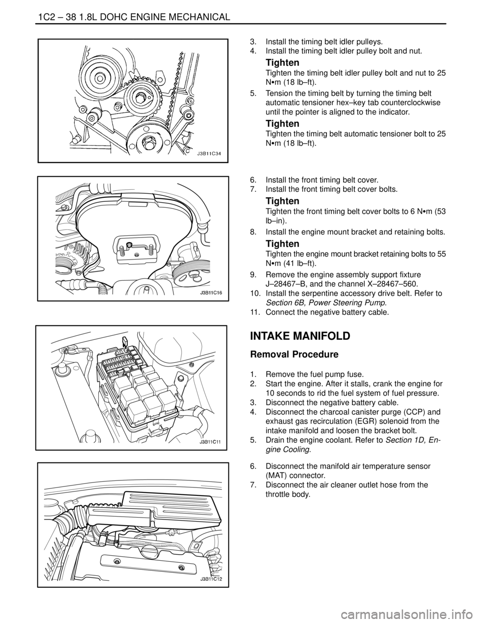
3. Install the timing belt idler pulleys.
4. Install the timing belt idler pulley bolt and nut.
Tighten
Tighten the timing belt idler pulley bolt and nut to 25
NSm (18 lb–ft).
5. Tension the timing belt by turning the timing belt
automatic tensioner hex–key tab counterclockwise
until the pointer is aligned to the indicator.
Tighten
Tighten the timing belt automatic tensioner bolt to 25
NSm (18 lb–ft).
6. Install the front timing belt cover.
7. Install the front timing belt cover bolts.
Tighten
Tighten the front timing belt cover bolts to 6 NSm (53
lb–in).
8. Install the engine mount bracket and retaining bolts.
Tighten
Tighten the engine mount bracket retaining bolts to 55
NSm (41 lb–ft).
9. Remove the engine assembly support fixture
J–28467–B, and the channel X–28467–560.
10. Install the serpentine accessory drive belt. Refer to
Section 6B, Power Steering Pump.
11. Connect the negative battery cable.
INTAKE MANIFOLD
Removal Procedure
1. Remove the fuel pump fuse.
2. Start the engine. After it stalls, crank the engine for
10 seconds to rid the fuel system of fuel pressure.
3. Disconnect the negative battery cable.
4. Disconnect the charcoal canister purge (CCP) and
exhaust gas recirculation (EGR) solenoid from the
intake manifold and loosen the bracket bolt.
5. Drain the engine coolant. Refer to Section 1D, En-
gine Cooling.
6. Disconnect the manifold air temperature sensor
(MAT) connector.
7. Disconnect the air cleaner outlet hose from the
throttle body.