Page 1952 of 2643
POWER STEERING GEAR 6C – 35
DAEWOO V–121 BL4
1. Steering Wheel
2. SSPS control module
3. Steering Wheel Rotation Sensor
4. Steering Column
Checking procedure is as follows;
1. Remove SSPS connector2. Turn the ignition ON
3. Try to measure 5V across A and C terminals. If you
fail, it might be A, C wiring open or short, or SSPS
module malfunction.
4. Check if B+ and B– are supplied to terminal �8"
and �10" respectively.
TERMINAL
VOLTAGERESISTANCECONDITION
A�C4.8 – 5.2 V9.0 – 10 KWIdle
B�C0.5 – 4.5 V0.7 – 12 KWSteering
Page 1955 of 2643

SECTION : 6E
STEERING WHEEL AND COLUMN
CAUTION : Disconnect the negative battery cable before removing or installing any electrical unit or when a tool
or equipment could easily come in contact with exposed electrical terminals. Disconnecting this cable will help
prevent personal injury and damage to the vehicle. The ignition must also be in LOCK unless otherwise noted.
TABLE OF CONTENTS
SPECIFICATIONS6E–1 . . . . . . . . . . . . . . . . . . . . . . . . . .
Fastener Tightening Specifications 6E–1. . . . . . . . . . .
SPECIAL TOOLS6E–2 . . . . . . . . . . . . . . . . . . . . . . . . . . .
Special Tools Table 6E–2. . . . . . . . . . . . . . . . . . . . . . . .
DIAGNOSIS6E–2 . . . . . . . . . . . . . . . . . . . . . . . . . . . . . . . .
Steering Column Diagnosis 6E–2. . . . . . . . . . . . . . . . .
MAINTENANCE AND REPAIR6E–8 . . . . . . . . . . . . . . .
ON–VEHICLE SERVICE 6E–8. . . . . . . . . . . . . . . . . . . . .
Headlamp/Turn Signal Switch and Lever 6E–8. . . . . .
Wiper Switch and Lever 6E–9. . . . . . . . . . . . . . . . . . . . Steering Wheel Rotation Sensor 6E–10. . . . . . . . . . . .
Steering Wheel Without SIR 6E–11. . . . . . . . . . . . . . . .
Steering Wheel With SIR 6E–13. . . . . . . . . . . . . . . . . .
Ignition Lock Cylinder and Switch 6E–13. . . . . . . . . . .
Steering Column 6E–15. . . . . . . . . . . . . . . . . . . . . . . . . .
UNIT REPAIR 6E–19. . . . . . . . . . . . . . . . . . . . . . . . . . . . .
Tilt Steering Column 6E–19. . . . . . . . . . . . . . . . . . . . . .
GENERAL DESCRIPTION AND SYSTEM
OPERATION6E–20 . . . . . . . . . . . . . . . . . . . . . . . . . . . . .
Steering Wheel and Column 6E–20. . . . . . . . . . . . . . . .
Ignition Key Reminder 6E–20. . . . . . . . . . . . . . . . . . . . .
SPECIFICATIONS
FASTENER TIGHTENING SPECIFICATIONS
ApplicationNSmLb–FtLb–In
Ignition Switch Housing Shear Bolts11–97
Ignition Switch Retaining Screw2.5–22
Steering Column Jacket Assembly Front Bracket Bolts2216–
Steering Column Jacket Assembly Rear Bracket Nuts2216–
Steering Shaft Universal Joint Pinch Bolt2518–
Steering Wheel Horn Cap Screws4.5–40
Steering Wheel Nut3828–
Steering Wheel Rotation Sensor Retaining Screw2–18
Support Housing Screws1612–
Turn Signal Switch Housing Screws3–27
Upper and Lower Steering Column Cover Panel Screws2.5–22
Page 1956 of 2643
6E – 2ISTEERING WHEEL AND COLUMN
DAEWOO V–121 BL4
SPECIAL TOOLS
SPECIAL TOOLS TABLE
KM–210–A
Steering Wheel Puller
DIAGNOSIS
STEERING COLUMN DIAGNOSIS
Lock System
Lock System Will Not Unlock
ChecksAction
Check the lock cylinder for damage.Replace the lock cylinder.
Check the ignition switch for lack of free movement.Lubricate the ignition switch.
Check the steering column housing for binding or damage.Remove the steering shaft and clear the steering column
housing. Replace the steering column housing as needed.
Lock System Will Not Lock
ChecksAction
Check the lock cylinder for damage.Replace the lock cylinder.
Check the ignition switch for a lack of free movement.Lubricate the ignition switch.
Check the steering column housing for binding or damage.Remove the steering shaft and clear the steering column
housing. Replace the steering column housing as needed.
Page 1957 of 2643

STEERING WHEEL AND COLUMN 6E – 3
DAEWOO V–121 BL4
High Lock Effort
ChecksAction
Check the lock cylinder for damage.Replace the lock cylinder.
Check the ignition switch for lack of free movement.Lubricate the ignition switch.
Check for extreme misalignment of the housing to the cov-
er.Realign the cover on the housing. Replace the cover as
needed.
Check for a bent ignition switch mounting bracket.Replace the ignition switch mounting bracket.
Key Cannot Be Removed in the LOCK Position
ChecksAction
Check to see that the ignition switch is set correctly.Reset the ignition switch.
Check the lock cylinder for damage.Replace the lock cylinder.
Check the fuse F17 from the I/P fuse block.Replace the fuse F17
Check for an open or short in the circuit between terminal
2 of key interlock solenoid and the I/P fuse block.Replace the fuse F17
Select the gear shift lever to ”P” position.
Check the resistance between the terminal 2 and 1 of the
”P” position switch.Replace the ”P” position switch.
Check for an open or short in the circuit between the
ground G202 and terminal 1 of the key interlock unit.Replace the open or short from the circuit.
Turn the ignition ON.
Select the gear shift lever to ”P” position.
Check the resistance between the terminal 1 and 2 of the
key interlock solenoid.Replace the key interlock solenoid.
Page 1961 of 2643

STEERING WHEEL AND COLUMN 6E – 7
DAEWOO V–121 BL4
Front or Rear Turn Signal Lights Not Flashing
ChecksAction
Check for a faulty turn signal switch.Replace the turn signal switch.
Check the chassis–to–column connector for an improper
connection.Reconnect the chassis–to–column connector.
Turn Signal Lights Flash Very Slowly
ChecksAction
Check the chassis–to–column connector for an improper
connection.Reconnect the chassis–to–column connector.
Ignition Switch
Electrical System Will Not Function
ChecksAction
Check the ignition switch for damage.Replace the ignition switch.
Check the ignition switch for improper installation.Remove and inspect the ignition switch. Reinstall the igni-
tion switch.
Check the ignition switch electrical connector for improper
installation.Reconnect the ignition switch electrical connector.
Replace the ignition switch electrical connector.
Ignition Switch Will Not Turn
ChecksAction
Check the ignition switch for damage.Replace the ignition switch.
Check the ignition switch for improper installation.Remove and inspect the ignition switch. Reinstall the igni-
tion switch.
Wiper Lever and Switch
Switch Inoperative: No LOW, HIGH, INTERMITTENT or WASH
ChecksAction
Check the wiper lever and switch for damage.Replace the wiper lever and switch.
Check the wiper lever and switch for improper installation.Remove and inspect the wiper lever and switch.
Reinstall the wiper lever and switch.
Page 1967 of 2643

STEERING WHEEL AND COLUMN 6E – 13
DAEWOO V–121 BL4
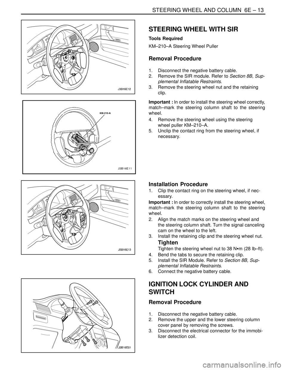
STEERING WHEEL WITH SIR
Tools Required
KM–210–A Steering Wheel Puller
Removal Procedure
1. Disconnect the negative battery cable.
2. Remove the SIR module. Refer to Section 8B, Sup-
plemental Inflatable Restraints.
3. Remove the steering wheel nut and the retaining
clip.
Important : In order to install the steering wheel correctly,
match–mark the steering column shaft to the steering
wheel.
4. Remove the steering wheel using the steering
wheel puller KM–210–A.
5. Unclip the contact ring from the steering wheel, if
necessary.
Installation Procedure
1. Clip the contact ring on the steering wheel, if nec-
essary.
Important : In order to correctly install the steering wheel,
match–mark the steering column shaft to the steering
wheel.
2. Align the match marks on the steering wheel and
the steering column shaft. Turn the signal canceling
cam on the wheel to the left.
3. Install the retaining clip and the steering wheel nut.
Tighten
Tighten the steering wheel nut to 38 NSm (28 lb–ft).
4. Bend the tabs to secure the retaining clip.
5. Install the SIR Module. Refer to Section 8B, Sup-
plemental Inflatable Restraints.
6. Connect the negative battery cable.
IGNITION LOCK CYLINDER AND
SWITCH
Removal Procedure
1. Disconnect the negative battery cable.
2. Remove the upper and the lower steering column
cover panel by removing the screws.
3. Disconnect the electrical connector for the immobi-
lizer detection coil.
Page 1968 of 2643
6E – 14ISTEERING WHEEL AND COLUMN
DAEWOO V–121 BL4
4. With the key in the ignition turned to the position
designated ACC, remove the lock cylinder by
pressing down the detent spring and pulling the
lock cylinder out of the switch cylinder housing.
5. Remove the ignition switch retaining screw.
6. Disconnect the wiring and remove the ignition
switch.
Installation Procedure
1. Install the ignition switch with the ignition switch
retaining screw.
Tighten
Tighten the ignition switch retaining screw to 2.5 NSm
(22 lb–in).
2. Connect the wiring to the ignition switch.
3. Install the lock cylinder.
4. Connect the electrical connector for the immobilizer
detection unit.
5. Install the upper and the lower steering column cov-
er panel with the screws.
Tighten
Tighten the upper and the lower steering column cov-
er panel screws to 2.5 NSm (22 lb–in).
6. Connect the negative battery cable.
Page 1969 of 2643

STEERING WHEEL AND COLUMN 6E – 15
DAEWOO V–121 BL4
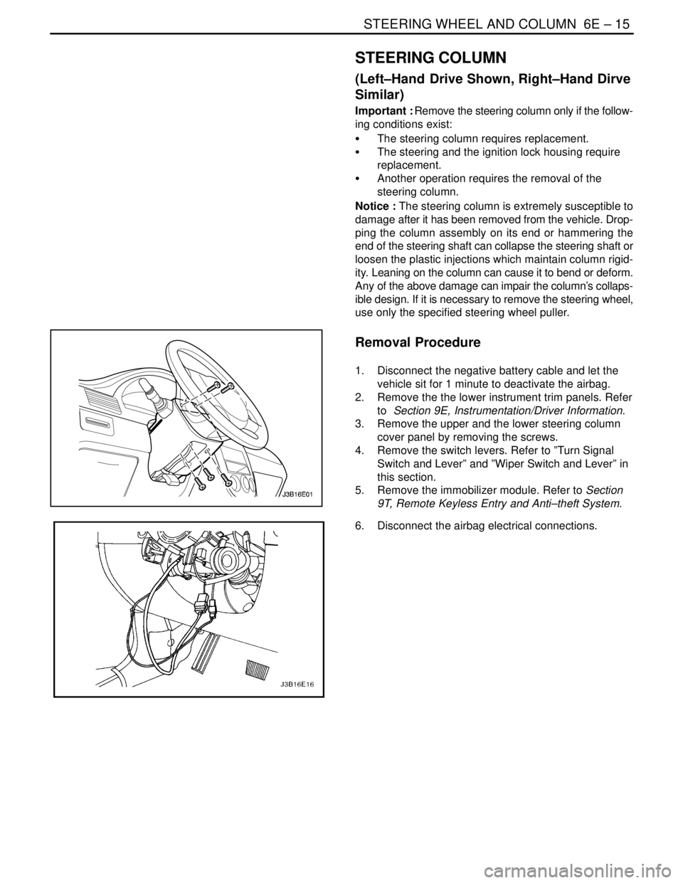
STEERING COLUMN
(Left–Hand Drive Shown, Right–Hand Dirve
Similar)
Important : Remove the steering column only if the follow-
ing conditions exist:
S The steering column requires replacement.
S The steering and the ignition lock housing require
replacement.
S Another operation requires the removal of the
steering column.
Notice : The steering column is extremely susceptible to
damage after it has been removed from the vehicle. Drop-
ping the column assembly on its end or hammering the
end of the steering shaft can collapse the steering shaft or
loosen the plastic injections which maintain column rigid-
ity. Leaning on the column can cause it to bend or deform.
Any of the above damage can impair the column’s collaps-
ible design. If it is necessary to remove the steering wheel,
use only the specified steering wheel puller.
Removal Procedure
1. Disconnect the negative battery cable and let the
vehicle sit for 1 minute to deactivate the airbag.
2. Remove the the lower instrument trim panels. Refer
to Section 9E, Instrumentation/Driver Information.
3. Remove the upper and the lower steering column
cover panel by removing the screws.
4. Remove the switch levers. Refer to ”Turn Signal
Switch and Lever” and ”Wiper Switch and Lever” in
this section.
5. Remove the immobilizer module. Refer to Section
9T, Remote Keyless Entry and Anti–theft System.
6. Disconnect the airbag electrical connections.