Page 1332 of 2643
 HATCH BACKa. CONNECTOR INFORMATION
CONNECTOR(NO.)
(PIN NO. COLOR)
CONNECTING, WIRING HARNESSCONNECTOR POSITION
C101 (21 Pin, White)Body � Engine Fuse BlockEngine")
5–172WELECTRICAL WIRING DIAGRAMS
2) HATCH BACKa. CONNECTOR INFORMATION
CONNECTOR(NO.)
(PIN NO. COLOR)
CONNECTING, WIRING HARNESSCONNECTOR POSITION
C101 (21 Pin, White)Body � Engine Fuse BlockEngine Fuse Block
C102 (11 Pin, White)Body � Engine Fuse BlockEngine Fuse Block
C105 (4 Pin, White)Body � Engine Fuse BlockEngine Fuse Block
C201 (76 Pin, Black)I.P � I.P Fuse BlockI.P Fuse Block
C202 (89 Pin, White)I.P � BodyLeft CO–Driver Leg Room
C204 (8 Pin, White)Roof – Body (W/O Rain Sensor)Left CO�Driver Leg Room
C204 (14 Pin, White)Roof – Body (W/ Rain Sensor)Left CO�Driver Leg Room
C351 (33 Pin, Gray)Body � Front Light DoorUnder CO–Driver A Pillar
C361 (33 Pin, Gray)Body � Front Right DoorUnder Driver A Pillar
C371 (12 Pin, White)Body � Rear Light DoorUnder Left B Pillar
C381 (12 Pin, White)Body � Rear Right DoorUnder Right B Pillar
S203 (Red)I.PBehind Audio Mounting
S204 (Magenta)I.PBehind Audio Mounting
G203I.PBehind Left Audio Bracket
b. CONNECTOR IDENTIFICATION SYMBOL & PIN NUMBER POSITION
Page 1338 of 2643
5–178WELECTRICAL WIRING DIAGRAMS
28. AIR BAG (SDM: SENSING & DIAGNOSTIC MODULE) CIRCUITa. CONNECTOR INFORMATION
CONNECTOR(NO.)
(PIN NO. COLOR)
CONNECTING, WIRING HARNESSCONNECTOR POSITION
C201 (76 Pin, Black)I.P � I.P Fuse BlockI.P Fuse Block
C202 (89 Pin, White)I.P � BodyLeft CO–Driver Leg Room
C207 (6 Pin, White)Air Bag � I.PUpper Left Driver Leg Room
C301 (8 Pin, White)Air Bag � BodyFront SDM
G202Air BagBehind Left Audio Bracket
G301BodyBelow Driver Cross Member Floor Panel
b. CONNECTOR IDENTIFICATION SYMBOL & PIN NUMBER POSITION
Page 1342 of 2643
5–182WELECTRICAL WIRING DIAGRAMS
30. SSPS (SPEED SENSITIVE POWER STEERING) CIRCUITa. CONNECTOR INFORMATION
CONNECTOR(NO.)
(PIN NO. COLOR)
CONNECTING, WIRING HARNESSCONNECTOR POSITION
C102 (11 Pin, White)Body � Engine Fuse BlockEngine Fuse Block
C106 (20 Pin, White)Engine � Engine Fuse BlockEngine Fuse Block
C108 (24 Pin, Black)Body � EngineLeft Engine Fuse Block
C113 (16 Pin, Black)Body � FrontBehind ECM Bracket
C201 (76 Pin, Black)I.P � I.P Fuse BlockI.P Fuse Block
C202 (89 Pin, White)I.P � BodyLeft CO–Driver Leg Room
C206 (22 Pin, White)I.P � TCMUpper Driver Leg Room
S202 (Black)I.PBehind Cluster
S203 (Red)I.PBehind Audio Mounting
G104EngineUnder Start Motor
G203I.PBehind Left Audio Bracket
b. CONNECTOR IDENTIFICATION SYMBOL & PIN NUMBER POSITION
Page 1344 of 2643
5–184WELECTRICAL WIRING DIAGRAMS
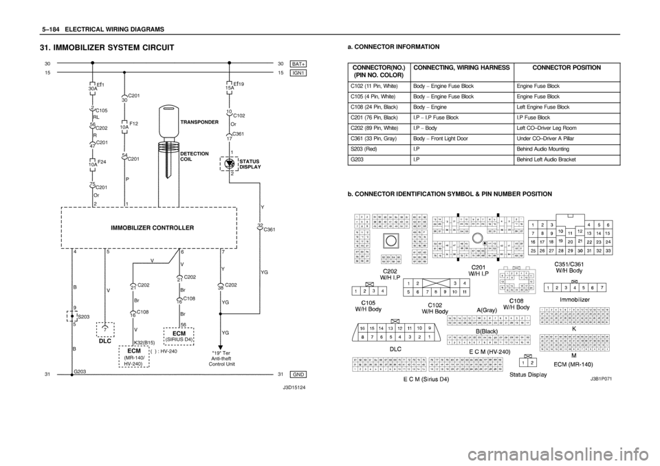
31. IMMOBILIZER SYSTEM CIRCUITa. CONNECTOR INFORMATION
CONNECTOR(NO.)
(PIN NO. COLOR)
CONNECTING, WIRING HARNESSCONNECTOR POSITION
C102 (11 Pin, White)Body � Engine Fuse BlockEngine Fuse Block
C105 (4 Pin, White)Body � Engine Fuse BlockEngine Fuse Block
C108 (24 Pin, Black)Body � EngineLeft Engine Fuse Block
C201 (76 Pin, Black)I.P � I.P Fuse BlockI.P Fuse Block
C202 (89 Pin, White)I.P � BodyLeft CO–Driver Leg Room
C361 (33 Pin, Gray)Body � Front Light DoorUnder CO–Driver A Pillar
S203 (Red)I.PBehind Audio Mounting
G203I.PBehind Left Audio Bracket
b. CONNECTOR IDENTIFICATION SYMBOL & PIN NUMBER POSITION
J3B1P071
Page 2206 of 2643

DAEWOO V–121 BL4
spring should never be disassembled, and there is no
timekeeping function. The clock spring contains two or
three current–carry")
8B – 102ISUPPLEMENTAL INFLATABLE RESTRAINTS (SIR)
DAEWOO V–121 BL4
spring should never be disassembled, and there is no
timekeeping function. The clock spring contains two or
three current–carrying coils. One of the current–carrying
coils maintains continuous contact within the driver de-
ployment loop while the steering wheel is rotated. The
clock spring also contains coils that maintain continuous
contact for horn and remote audio control switch circuit.
Turning the steering wheel in one direction tightens the
coil, and turning the steering wheel in the opposite direc-
tion loosens the coil. Do not turn the clock spring when the
steering wheel is not attached. Refer to ”Clock Spring” in
this section for proper installation of the clock spring.
The clock spring also includes the wiring and the connec-
tors for the horn circuit and the driver airbag circuit. A yel-
low two–way connector on the lower steering column is at-
tached to the clock spring wiring. The yellow connector to
the airbag contains a shorting bar which connects the driv-
er high circuit to driver low circuit when the connector is
disconnected.
The shorting bar prevents current from travelling through
the driver airbag module during servicing. The shorting bar
is disengaged when the clock spring connector is con-
nected.WIRING HARNESS CONNECTORS
If the sensing and diagnostic module (SDM) electrical con-
nector is not attached properly, a built in shorting bar will
connect the wire from airbag warning lamp with the SDM
ground wire. This turns on the airbag indicator . To prevent
deployment during servicing, additional shorting bars are
located in following locations :
S The clock spring electrical connector at the lower
steering column.
S The passenger airbag module.
S The driver airbag module.
S The seat belt pretensioners.
The shorting bar is only a backup safety device. Always
disable the supplemental inflatable restraints(SIR) before
beginning any service procedure.
Page 2220 of 2643
9A – 14IBODY WIRING SYSTEM
DAEWOO V–121 BL4
I/P Fuse Block
FuseRating/SourceCircuit
F110AIGN 1SDM
F210AIGN 1TCM, ECM, Generator, VGIS, VSS
F315AIGN 1Hazard Switch
F410AIGN 1Cluster, DRL Module, Chime Bell, Brake Switch,
SSPS Module, A/C Control Switch
F5–Spare–
F610AIGN 2A/C Comp. Relay, Defog Relay, Power Window
Relay, Head Lamp Relay
F720AIGN 2Blower Relay, A/C Control Switch, FATC
F815AIGN 2Electric Mirror Switch, Folding Mirror, Sun Roof
Module
F925AIGN 1Wiper Motor, Wiper Switch
F10–Spare–
F1110AIGN 1EBCM, Oil Feeding Connector
F1210AIGN 1Immobilizer, Anti Theft Control Unit, Rain Sensor
Unit
F1310AB+TCM
F1415AB+Hazard Switch
F1515AB+Anti Theft Control Unit
F1610AB+DLC
F1710AACCAudio, Clock
F1815AACCExtra Power Jack
F1915AACCCigar Lighter
F2010AIGN 1Reverse Lamp Switch, PNP Switch
F2115AB+Rear Fog Relay
F2215AB+Clock, FATC, A/C Control Switch
F2315AB+Audio
F2410AB+Immobilizer
Page 2323 of 2643

9E – 24IINSTRUMENTATION/DRIVER INFORMATION
DAEWOO V–121 BL4
Installation Procedure
1. Connect the electrical connectors.
2. Install the instrument cluster dimmer switch assem-
bly.
INSTRUMENT CLUSTER INDICATOR
LAMPS
Removal Procedure
1. Disconnect the negative battery cable.
2. Remove the instrument cluster. Refer to ”Instru-
ment Cluster” in this section.
3. Remove the defective bulb from the rear of the
cluster.
Installation Procedure
1. Install the new bulb.
2. Install the instrument cluster. Refer to ”Instrument
Cluster” in this section.
3. Connect the negative battery cable.
INSTRUMENT PANEL
Removal Procedure
1. Disconnect the negative battery cable.
2. Remove the floor console. Refer to Section 9G,
Interior Trim.
3. Remove the sun sensor. Refer to Section 7D, Auto-
matic Temperature Control Heating, Ventilation, and
Air Condition System.
4. Remove the stereo cassette AM/FM radio. Refer to
Section 9F, Audio Systems.
5. Remove the center molding.
6. Remove the instrument cluster dimmer switch as-
sembly.
Page 2327 of 2643

9E – 28IINSTRUMENTATION/DRIVER INFORMATION
DAEWOO V–121 BL4
10. Install the instrument panel fuse block with the
screw.
11. Install the instrument panel side covers with the
screws.
12. Install the knee bolster. Refer to Section 9G, Interi-
or Trim.
13. Install the glove box and the glove box housing.
Refer to ”Glove Box” in this section.
14. Install the instrument cluster. Refer to ”Instrument
Cluster” in this section.
15. Install the instrument cluster trim panel. Refer to
”Instrument Cluster Trim Panel” in this section.
16. Install the instrument cluster dimmer switch assem-
bly.
17. Install the stereo cassette AM/FM radio. Refer to
Section 9F, Audio Systems. Remove the center
molding.
18. Install the sun sensor. Refer to Section 7D, Auto-
matic Temperature Control Heating, Ventilation, and
Air Condition System.
19. Install the floor console. Refer to Section 9G, Interi-
or Trim.
20. Connect the negative battery cable.
CHIME MODULE
(Left–hand Drive Shown, Right–Hand Drive
Similar)
Removal Procedure
1. Disconnect the negative battery cable.
2. Remove the knee bolster trim panel beneath the
steering column.
3. Disconnect the electrical connector.
4. Remove the screws and the chime module.
 CIRCUITa. CONNECTOR INFORMATION
CONNECTOR(NO.)
(PIN NO. COLOR)
CONNECTING, WIRING HARNESSCONNECTOR POSITION
C201 (76 P")
 CIRCUITa. CONNECTOR INFORMATION
CONNECTOR(NO.)
(PIN NO. COLOR)
CONNECTING, WIRING HARNESSCONNECTOR POSITION
C102 (11 Pin, W")