2004 DAEWOO LACETTI steering wheel adjustment
[x] Cancel search: steering wheel adjustmentPage 910 of 2643
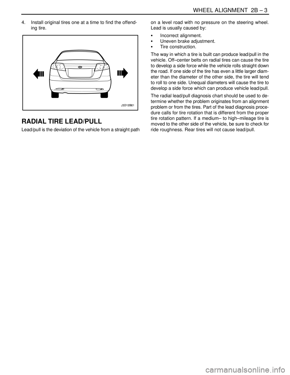
WHEEL ALIGNMENT 2B – 3
DAEWOO V–121 BL4
4. Install original tires one at a time to find the offend-
ing tire.
RADIAL TIRE LEAD/PULL
Lead/pull is the deviation of the vehicle from a straight pathon a level road with no pressure on the steering wheel.
Lead is usually caused by:
S Incorrect alignment.
S Uneven brake adjustment.
S Tire construction.
The way in which a tire is built can produce lead/pull in the
vehicle. Off–center belts on radial tires can cause the tire
to develop a side force while the vehicle rolls straight down
the road. If one side of the tire has even a little larger diam-
eter than the diameter of the other side, the tire will tend
to roll to one side. Unequal diameters will cause the tire to
develop a side force which can produce vehicle lead/pull.
The radial lead/pull diagnosis chart should be used to de-
termine whether the problem originates from an alignment
problem or from the tires. Part of the lead diagnosis proce-
dure calls for tire rotation that is different from the proper
tire rotation pattern. If a medium– to high–mileage tire is
moved to the other side of the vehicle, be sure to check for
ride roughness. Rear tires will not cause lead/pull.
Page 915 of 2643
2B – 8IWHEEL ALIGNMENT
DAEWOO V–121 BL4
PRELIMINARY INSPECTION
ChecksAction
Check the tires for proper inflation pressures and normal
tread wear.Inflate the tires to the proper tire pressure. Replace the
tires as needed.
Check the wheel bearings for looseness.Tighten the axle nut to the proper specification. Replace
the strut wheel bearing as needed.
Check for loose ball joints and tie rod ends.Tighten the ball joints and the tie rods.
Check the runout of the wheels and the tires.Measure and correct the tire runout.
Check the vehicle trim heights.Correct the trim heights. Make the correction before ad-
justing the toe.
Check for loose rack and pinion mounting.Tighten the mounting brackets for the rack and pinion as-
sembly.
Check for improperly operating struts.Replace the strut assembly.
Check for loose control arms.Tighten the control arm attachment bolts. Replace the con-
trol arm bushings as needed.
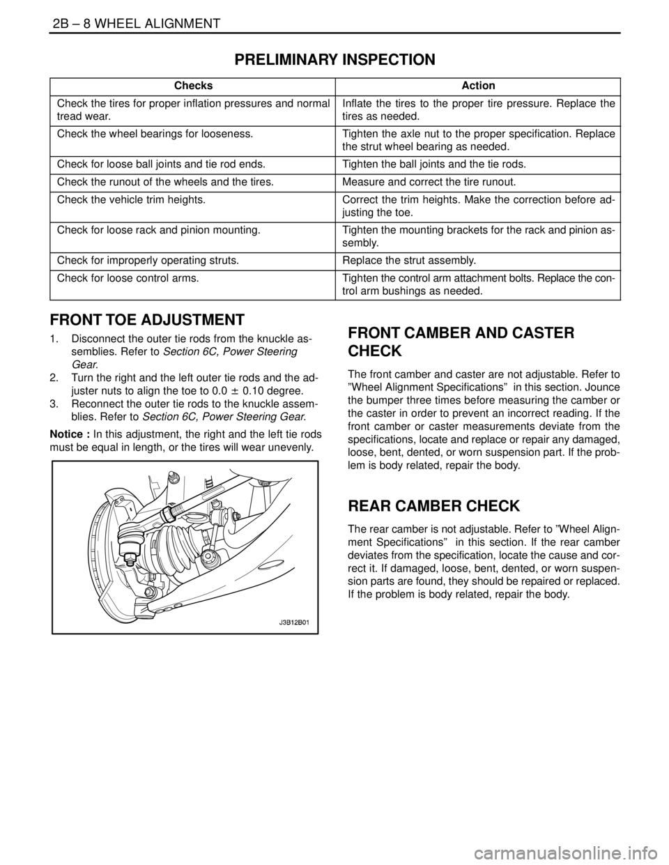
FRONT TOE ADJUSTMENT
1. Disconnect the outer tie rods from the knuckle as-
semblies. Refer to Section 6C, Power Steering
Gear.
2. Turn the right and the left outer tie rods and the ad-
juster nuts to align the toe to 0.0 ± 0.10 degree.
3. Reconnect the outer tie rods to the knuckle assem-
blies. Refer to Section 6C, Power Steering Gear.
Notice : In this adjustment, the right and the left tie rods
must be equal in length, or the tires will wear unevenly.FRONT CAMBER AND CASTER
CHECK
The front camber and caster are not adjustable. Refer to
”Wheel Alignment Specifications” in this section. Jounce
the bumper three times before measuring the camber or
the caster in order to prevent an incorrect reading. If the
front camber or caster measurements deviate from the
specifications, locate and replace or repair any damaged,
loose, bent, dented, or worn suspension part. If the prob-
lem is body related, repair the body.
REAR CAMBER CHECK
The rear camber is not adjustable. Refer to ”Wheel Align-
ment Specifications” in this section. If the rear camber
deviates from the specification, locate the cause and cor-
rect it. If damaged, loose, bent, dented, or worn suspen-
sion parts are found, they should be repaired or replaced.
If the problem is body related, repair the body.
Page 1920 of 2643

POWER STEERING GEAR 6C – 3
DAEWOO V–121 BL4
DIAGNOSIS
POWER RACK AND PINION STEERING GEAR
Hissing Noise
ChecksAction
Check the intermediate shaft joints for looseness.Tighten the intermediate shaft joints.
Check the power steering hose for contact with other com-
ponents.Be sure the power steering hose is correctly fitted into the
hose clips.
Rattling Noise in Steering Gear
ChecksAction
Check the power steering hose for contact with the body.Be sure the power steering hose is correctly fitted into the
hose clips.
Check the steering gear for insufficient lubrication.Lubricate the steering gear.
Check the steering gear mounting for improper installa-
tion.Tighten the steering gear mounting bracket nuts and bolts.
Check the outer tie rods for improper installation.Tighten the outer tie rod joints. Replace the outer tie rods.
Poor Return of Steering Wheel to Center
ChecksAction
Check the steering wheel for contact with the turn signal
housing.Adjust the turn signal housing.
Check the intermediate shaft joints for binding or loose-
ness.Replace the intermediate shaft.
Check the power steering pump flow control valve for
sticking and improper alignment.Replace the power steering pump.
Check the wheel alignment.Align the wheels.
Check the wheel bearings for wear or damage.Replace the wheel bearings.
Check the intermediate shaft joints for improper installa-
tion.Adjust the intermediate shaft between the steering gear
and the steering column.
Replace the intermediate shaft.
Check the outer tie rods and the ball joints for binding or
looseness.Tighten the tie rods and the ball joints. Replace the tie rods
and the ball joints.
Check the steering gear adjustments.Perform a straight–ahead check.
Check the steering column shaft seal for rubbing on the
shaft.Replace the dash seal.
Check the steering shaft bearings for binding.Replace the stub shaft bearings.
Momentary Increase in Effort When Turning the Wheel Quickly
ChecksAction
Check the power steering pump for internal leaks.Replace the power steering pump.
Check the hoses for damage or restricted flow.Replace the power steering hoses and/or pipes.
Check the power steering fluid level.Fill the power steering fluid reservoir.
Check the power steering pump flow control valve for
sticking and improper operation.Replace the power steering pump.
Page 1931 of 2643
6C – 14IPOWER STEERING GEAR
DAEWOO V–121 BL4
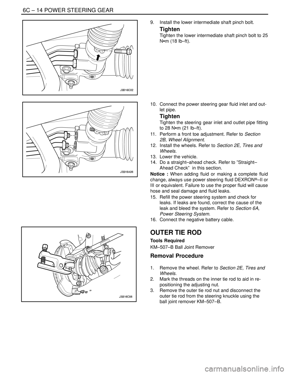
9. Install the lower intermediate shaft pinch bolt.
Tighten
Tighten the lower intermediate shaft pinch bolt to 25
NSm (18 lb–ft).
10. Connect the power steering gear fluid inlet and out-
let pipe.
Tighten
Tighten the steering gear inlet and outlet pipe fitting
to 28 NSm (21 lb–ft).
11. Perform a front toe adjustment. Refer to Section
2B, Wheel Alignment.
12. Install the wheels. Refer to Section 2E, Tires and
Wheels.
13. Lower the vehicle.
14. Do a straight–ahead check. Refer to ”Straight–
Ahead Check” in this section.
Notice : When adding fluid or making a complete fluid
change, always use power steering fluid DEXRON®–II or
III or equivalent. Failure to use the proper fluid will cause
hose and seal damage and fluid leaks.
15. Refill the power steering system and check for
leaks. If leaks are found, correct the cause of the
leak and bleed the system. Refer to Section 6A,
Power Steering System.
16. Connect the negative battery cable.
OUTER TIE ROD
Tools Required
KM–507–B Ball Joint Remover
Removal Procedure
1. Remove the wheel. Refer to Section 2E, Tires and
Wheels.
2. Mark the threads on the inner tie rod to aid in re-
positioning the adjusting nut.
3. Remove the outer tie rod nut and disconnect the
outer tie rod from the steering knuckle using the
ball joint remover KM–507–B.
Page 1932 of 2643
POWER STEERING GEAR 6C – 15
DAEWOO V–121 BL4
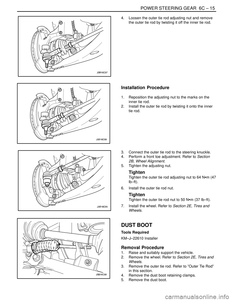
4. Loosen the outer tie rod adjusting nut and remove
the outer tie rod by twisting it off the inner tie rod.
Installation Procedure
1. Reposition the adjusting nut to the marks on the
inner tie rod.
2. Install the outer tie rod by twisting it onto the inner
tie rod.
3. Connect the outer tie rod to the steering knuckle.
4. Perform a front toe adjustment. Refer to Section
2B, Wheel Alignment.
5. Tighten the adjusting nut.
Tighten
Tighten the outer tie rod adjusting nut to 64 NSm (47
lb–ft).
6. Install the outer tie rod nut.
Tighten
Tighten the outer tie rod nut to 50 NSm (37 lb–ft).
7. Install the wheel. Refer to Section 2E, Tires and
Wheels.
DUST BOOT
Tools Required
KM–J–22610 Installer
Removal Procedure
1. Raise and suitably support the vehicle.
2. Remove the wheel. Refer to Section 2E, Tires and
Wheels.
3. Remove the outer tie rod. Refer to ”Outer Tie Rod”
in this section.
4. Remove the dust boot retaining clamps.
5. Remove the dust boot.
Page 1942 of 2643
POWER STEERING GEAR 6C – 25
DAEWOO V–121 BL4
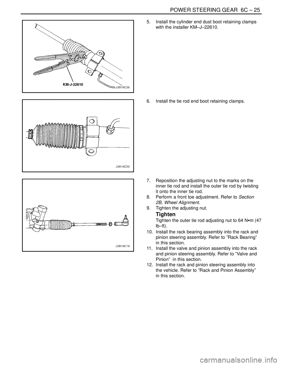
5. Install the cylinder end dust boot retaining clamps
with the installer KM–J–22610.
6. Install the tie rod end boot retaining clamps.
7. Reposition the adjusting nut to the marks on the
inner tie rod and install the outer tie rod by twisting
it onto the inner tie rod.
8. Perform a front toe adjustment. Refer to Section
2B, Wheel Alignment.
9. Tighten the adjusting nut.
Tighten
Tighten the outer tie rod adjusting nut to 64 NSm (47
lb–ft).
10. Install the rack bearing assembly into the rack and
pinion steering assembly. Refer to ”Rack Bearing”
in this section.
11. Install the valve and pinion assembly into the rack
and pinion steering assembly. Refer to ”Valve and
Pinion” in this section.
12. Install the rack and pinion steering assembly into
the vehicle. Refer to ”Rack and Pinion Assembly”
in this section.
Page 1947 of 2643
6C – 30IPOWER STEERING GEAR
DAEWOO V–121 BL4
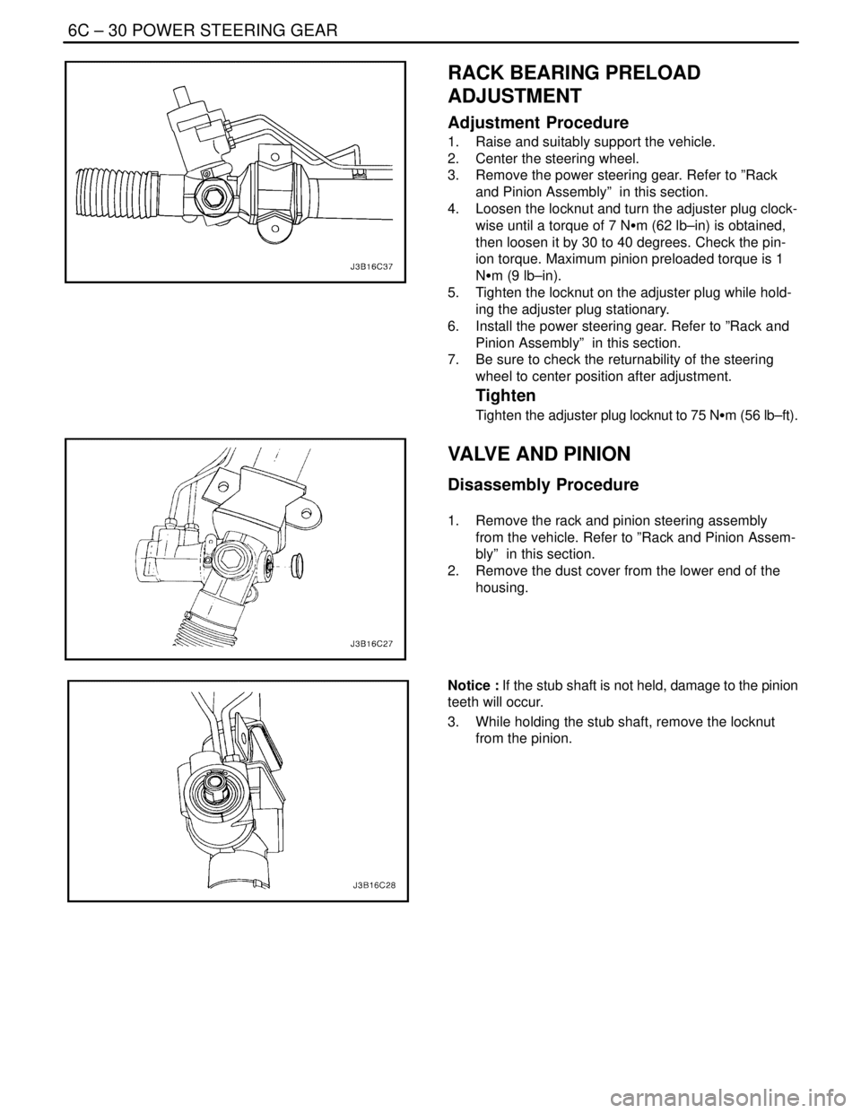
RACK BEARING PRELOAD
ADJUSTMENT
Adjustment Procedure
1. Raise and suitably support the vehicle.
2. Center the steering wheel.
3. Remove the power steering gear. Refer to ”Rack
and Pinion Assembly” in this section.
4. Loosen the locknut and turn the adjuster plug clock-
wise until a torque of 7 NSm (62 lb–in) is obtained,
then loosen it by 30 to 40 degrees. Check the pin-
ion torque. Maximum pinion preloaded torque is 1
NSm (9 lb–in).
5. Tighten the locknut on the adjuster plug while hold-
ing the adjuster plug stationary.
6. Install the power steering gear. Refer to ”Rack and
Pinion Assembly” in this section.
7. Be sure to check the returnability of the steering
wheel to center position after adjustment.
Tighten
Tighten the adjuster plug locknut to 75 NSm (56 lb–ft).
VALVE AND PINION
Disassembly Procedure
1. Remove the rack and pinion steering assembly
from the vehicle. Refer to ”Rack and Pinion Assem-
bly” in this section.
2. Remove the dust cover from the lower end of the
housing.
Notice : If the stub shaft is not held, damage to the pinion
teeth will occur.
3. While holding the stub shaft, remove the locknut
from the pinion.