Page 131 of 2643

1.8L DOHC ENGINE MECHANICAL 1C2 – 11
DAEWOO V–121 BL4
1. Connecting Rod
2. Bearing Set
3. Connecting Rod Bolt
4. Piston Ring Set
5. Piston Pin
6. Piston
7. Engine Block
8. Sleeve
9. Water Jacket Cap
10. Bolt (Manual Transaxle)
11. Flywheel (Manual Transaxle)
12. Flexible Plate (Automatic Transaxle)
13. Bolt (Automatic Transaxle)
14. Clamp
15. Hose
16. Clamp
17. Engine Ventilation Pipe
18. Bolt
19. Gasket
20. Needle Sleeve
21. Crankshaft Rear Seal
22. Crankshaft
23. Transmitter Disk
24. Bolt
25. Oil Pan Scraper
26. Oil Pan
27. Drain Plug
28. Washer
29. Bolt
30. Sleeve
31. Gasket
32. Bolt
33. Oil Pump Cover
34. Ring Gear
35. Gear
36. Oil Pressure Switch
37. Washer
38. Washer
39. Oil Duct Outlet Plug
40. Connecting Piece
41. Seal Ring
42. Oil Filter43. Bypass Valve
44. Pressure Relief Valve Plunger
45. Pressure Relief Valve Spring
46. Seal Ring
47. Pressure Relief Valve Plug
48. Seal Ring
49. Bolt
50. Oil Suction Pipe
51. Bolt
52. Rear Timing Belt Cover
53. Bolt
54. Special Bolt
55. Idler Pulley
56. Stud
57. Nut
58. Bolt
59. Tensioner
60. Bolt
61. Thrust Inner Washer
62. Woodruff Key
63. Crankshaft Gear
64. Thrust Outer Washer
65. Bolt
66. Camshaft Drive Belt
67. Gasket
68. Front Timing Belt Cover
69. Bolt
70. Bushing Plug
71. Bushing
72. Oil Gallery Plug
73. Bolt
74. Water Pump
75. Seal Ring
76. Crankshaft Position Sensor
77. Bolt
78. Knock Sensor*
79. Bolt
80. Bolt
81. Crankshaft Bearing Bridge
* : 2.0L DOHC Engine
Page 146 of 2643
1C2 – 26I1.8L DOHC ENGINE MECHANICAL
DAEWOO V–121 BL4
17. Align the camshaft gear timing marks. Use the ex-
haust gear mark for the exhaust gear and the in-
take gear mark for the intake gear, since the gears
are interchangeable
18. Loosen the automatic tensioner bolt. To relieve the
belt tension, turn the hex–key tab counterclockwise.
19. Rotate the automatic tensioner hex–key tab clock-
wise until the adjust arm pointer of the timing belt
automatic tensioner is aligned with the notch in the
timing belt automatic tensioner bracket.
20. Tighten the automatic tensioner bolt.
21. Rotate the crankshaft two full turns clockwise using
the crankshaft gear bolt.
22. Check the automatic tensioner pointer.
23. When the adjust arm pointer of the timing belt auto-
matic tensioner is aligned with the notch on the tim-
ing belt automatic tensioner bracket, the belt is ten-
sioned correctly.
Tighten
Tighten the automatic tensioner bolt to 25 NSm (18 lb–
ft).
Page 149 of 2643
1.8L DOHC ENGINE MECHANICAL 1C2 – 29
DAEWOO V–121 BL4
15. Using the crankshaft gear bolt, rotate the crank-
shaft clockwise until the timing mark on the crank-
shaft gear is aligned with the notch at the bottom of
the rear timing belt cover.
Notice : The camshaft gears must align with the notch on
the camshaft cover or damage to the engine could result.
16. Align the camshaft gears with the notch on the
camshaft cover.
Important : Use the intake gear mark for the intake cam-
shaft gear and the exhaust gear mark for the exhaust cam-
shaft gear since both gears are interchangeable.
17. Remove the timing belt.
18. Loosen the automatic tensioner bolt. Turn the hex–
key tab to relieve belt tension.
Installation Procedure
1. Align the timing mark on the crankshaft gear with
the notch on the bottom of the rear timing belt cov-
er.
Page 150 of 2643
1C2 – 30I1.8L DOHC ENGINE MECHANICAL
DAEWOO V–121 BL4
2. Align the timing marks on the camshaft gears, us-
ing the intake gear mark for the intake gear and the
exhaust gear mark for the exhaust gear.
3. Install the timing belt.
4. Turn the hex–key tab in a clockwise direction to
tension the belt. Turn until the pointer aligns with
the notch.
5. Install the automatic tensioner bolt.
Tighten
Tighten the automatic tensioner bolt to 25 NSm (18 lb–
ft).
6. Rotate the crankshaft two full turns clockwise using
the crankshaft pulley bolt.
7. Recheck the automatic tensioner pointer.
8. Install the front timing belt cover.
9. Install the front timing belt cover bolts.
Tighten
Tighten the front timing belt cover bolts to 6 NSm (53
lb–in).
10. Install the right engine mount bracket. Refer to ”En-
gine Mounts” in this section.
Page 157 of 2643

1.8L DOHC ENGINE MECHANICAL 1C2 – 37
DAEWOO V–121 BL4
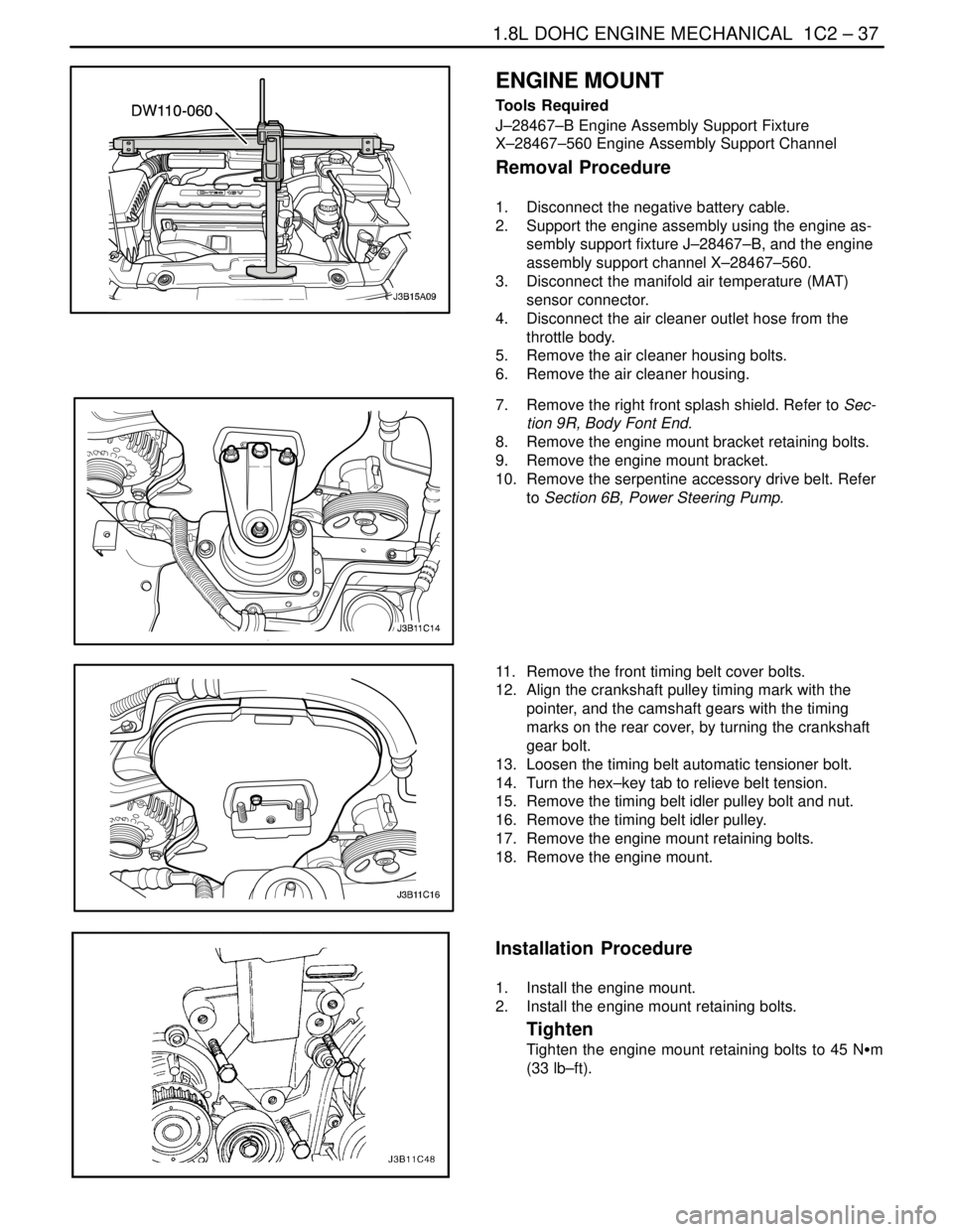
ENGINE MOUNT
Tools Required
J–28467–B Engine Assembly Support Fixture
X–28467–560 Engine Assembly Support Channel
Removal Procedure
1. Disconnect the negative battery cable.
2. Support the engine assembly using the engine as-
sembly support fixture J–28467–B, and the engine
assembly support channel X–28467–560.
3. Disconnect the manifold air temperature (MAT)
sensor connector.
4. Disconnect the air cleaner outlet hose from the
throttle body.
5. Remove the air cleaner housing bolts.
6. Remove the air cleaner housing.
7. Remove the right front splash shield. Refer to Sec-
tion 9R, Body Font End.
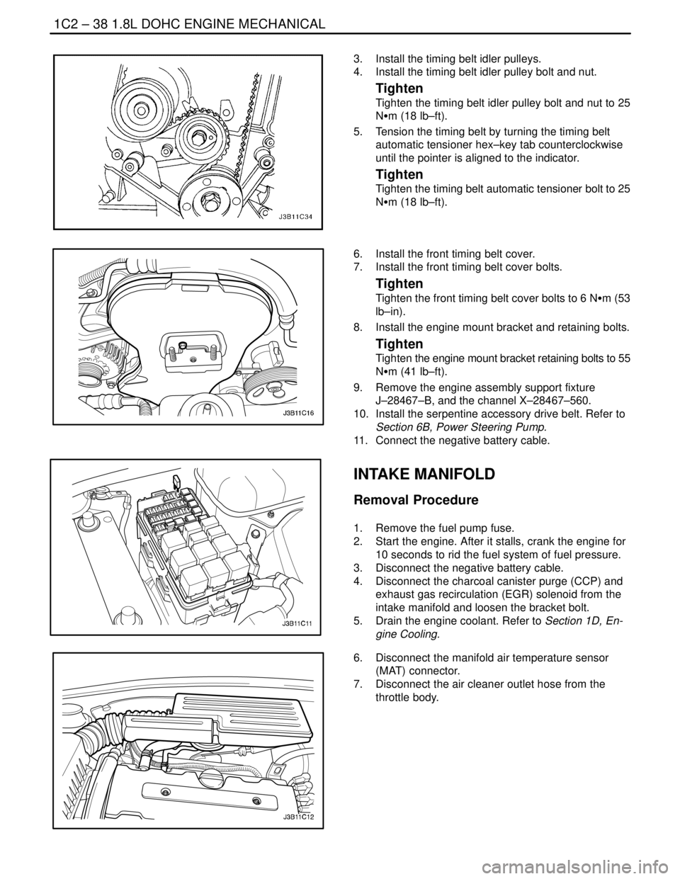
8. Remove the engine mount bracket retaining bolts.
9. Remove the engine mount bracket.
10. Remove the serpentine accessory drive belt. Refer
to Section 6B, Power Steering Pump.
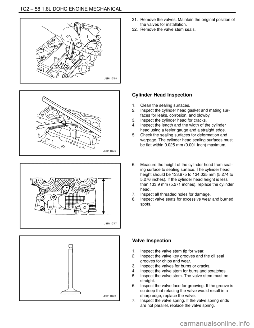
11. Remove the front timing belt cover bolts.
12. Align the crankshaft pulley timing mark with the
pointer, and the camshaft gears with the timing
marks on the rear cover, by turning the crankshaft
gear bolt.
13. Loosen the timing belt automatic tensioner bolt.
14. Turn the hex–key tab to relieve belt tension.
15. Remove the timing belt idler pulley bolt and nut.
16. Remove the timing belt idler pulley.
17. Remove the engine mount retaining bolts.
18. Remove the engine mount.
Installation Procedure
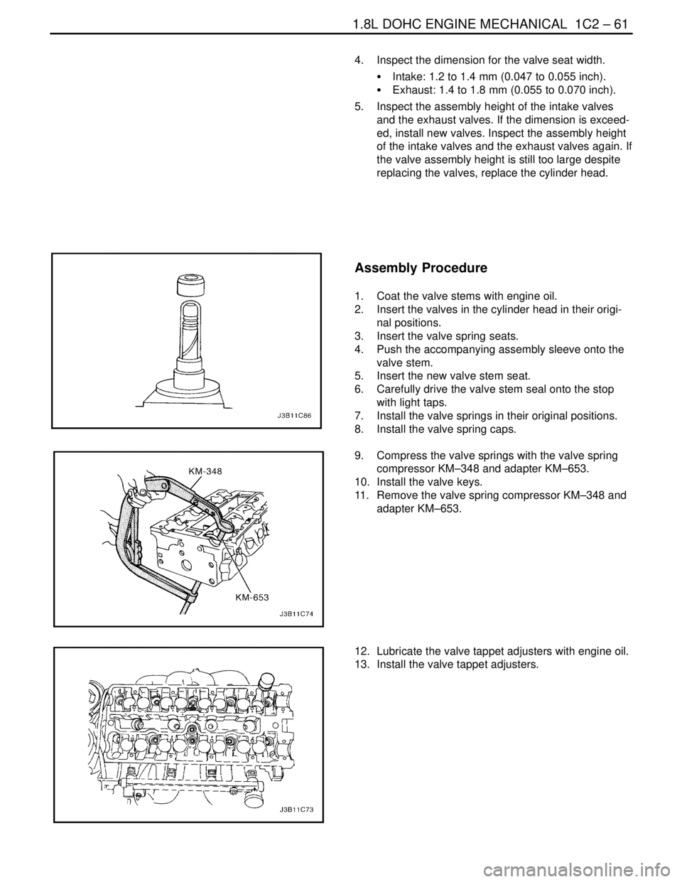
1. Install the engine mount.
2. Install the engine mount retaining bolts.
Tighten
Tighten the engine mount retaining bolts to 45 NSm
(33 lb–ft).
Page 158 of 2643

1C2 – 38I1.8L DOHC ENGINE MECHANICAL
DAEWOO V–121 BL4
3. Install the timing belt idler pulleys.
4. Install the timing belt idler pulley bolt and nut.
Tighten
Tighten the timing belt idler pulley bolt and nut to 25
NSm (18 lb–ft).
5. Tension the timing belt by turning the timing belt
automatic tensioner hex–key tab counterclockwise
until the pointer is aligned to the indicator.
Tighten
Tighten the timing belt automatic tensioner bolt to 25
NSm (18 lb–ft).
6. Install the front timing belt cover.
7. Install the front timing belt cover bolts.
Tighten
Tighten the front timing belt cover bolts to 6 NSm (53
lb–in).
8. Install the engine mount bracket and retaining bolts.
Tighten
Tighten the engine mount bracket retaining bolts to 55
NSm (41 lb–ft).
9. Remove the engine assembly support fixture
J–28467–B, and the channel X–28467–560.
10. Install the serpentine accessory drive belt. Refer to
Section 6B, Power Steering Pump.
11. Connect the negative battery cable.
INTAKE MANIFOLD
Removal Procedure
1. Remove the fuel pump fuse.
2. Start the engine. After it stalls, crank the engine for
10 seconds to rid the fuel system of fuel pressure.
3. Disconnect the negative battery cable.
4. Disconnect the charcoal canister purge (CCP) and
exhaust gas recirculation (EGR) solenoid from the
intake manifold and loosen the bracket bolt.
5. Drain the engine coolant. Refer to Section 1D, En-
gine Cooling.
6. Disconnect the manifold air temperature sensor
(MAT) connector.
7. Disconnect the air cleaner outlet hose from the
throttle body.
Page 178 of 2643

1C2 – 58I1.8L DOHC ENGINE MECHANICAL
DAEWOO V–121 BL4
31. Remove the valves. Maintain the original position of
the valves for installation.
32. Remove the valve stem seals.
Cylinder Head Inspection
1. Clean the sealing surfaces.
2. Inspect the cylinder head gasket and mating sur-
faces for leaks, corrosion, and blowby.
3. Inspect the cylinder head for cracks.
4. Inspect the length and the width of the cylinder
head using a feeler gauge and a straight edge.
5. Check the sealing surfaces for deformation and
warpage. The cylinder head sealing surfaces must
be flat within 0.025 mm (0.001 inch) maximum.
6. Measure the height of the cylinder head from seal-
ing surface to sealing surface. The cylinder head
height should be 133.975 to 134.025 mm (5.274 to
5.276 inches). If the cylinder head height is less
than 133.9 mm (5.271 inches), replace the cylinder
head.
7. Inspect all threaded holes for damage.
8. Inspect valve seats for excessive wear and burned
spots.
Valve Inspection
1. Inspect the valve stem tip for wear.
2. Inspect the valve key grooves and the oil seal
grooves for chips and wear.
3. Inspect the valves for burns or cracks.
4. Inspect the valve stem for burrs and scratches.
5. Inspect the valve stem. The valve stem must be
straight.
6. Inspect the valve face for grooving. If the groove is
so deep that refacing the valve would result in a
sharp edge, replace the valve.
7. Inspect the valve spring. If the valve spring ends
are not parallel, replace the valve spring.
Page 181 of 2643

1.8L DOHC ENGINE MECHANICAL 1C2 – 61
DAEWOO V–121 BL4
4. Inspect the dimension for the valve seat width.
S Intake: 1.2 to 1.4 mm (0.047 to 0.055 inch).
S Exhaust: 1.4 to 1.8 mm (0.055 to 0.070 inch).
5. Inspect the assembly height of the intake valves
and the exhaust valves. If the dimension is exceed-
ed, install new valves. Inspect the assembly height
of the intake valves and the exhaust valves again. If
the valve assembly height is still too large despite
replacing the valves, replace the cylinder head.
Assembly Procedure
1. Coat the valve stems with engine oil.
2. Insert the valves in the cylinder head in their origi-
nal positions.
3. Insert the valve spring seats.
4. Push the accompanying assembly sleeve onto the
valve stem.
5. Insert the new valve stem seat.
6. Carefully drive the valve stem seal onto the stop
with light taps.
7. Install the valve springs in their original positions.
8. Install the valve spring caps.
9. Compress the valve springs with the valve spring
compressor KM–348 and adapter KM–653.
10. Install the valve keys.
11. Remove the valve spring compressor KM–348 and
adapter KM–653.
12. Lubricate the valve tappet adjusters with engine oil.
13. Install the valve tappet adjusters.