Page 1160 of 2643
4G – 8IPARKING BRAKE
DAEWOO V–121 BL4
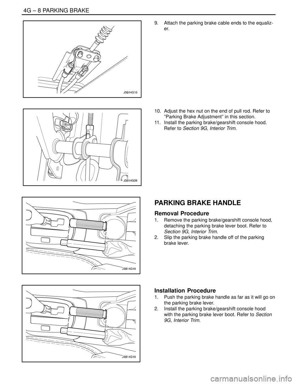
9. Attach the parking brake cable ends to the equaliz-
er.
10. Adjust the hex nut on the end of pull rod. Refer to
”Parking Brake Adjustment” in this section.
11. Install the parking brake/gearshift console hood.
Refer to Section 9G, Interior Trim.
PARKING BRAKE HANDLE
Removal Procedure
1. Remove the parking brake/gearshift console hood,
detaching the parking brake lever boot. Refer to
Section 9G, Interior Trim.
2. Slip the parking brake handle off of the parking
brake lever.
Installation Procedure
1. Push the parking brake handle as far as it will go on
the parking brake lever.
2. Install the parking brake/gearshift console hood
with the parking brake lever boot. Refer to Section
9G, Interior Trim.
Page 1542 of 2643
ZF 4 HP 16 AUTOMATIC TRANSAXLE 5A1 – 193
DAEWOO V–121 BL4
Repairing the Fluid Leak
The following are potential causes for fluid leaks. Check
and repair, as necessary.
S Fasteners are not tightened to specifications.
S Fastener threads and tapped holes are dirty or cor-
roded.
S Gaskets, seals or sleeves are misaligned, dam-
aged, or warped, or scratched.
S The manual shaft is nicked or damaged.
S There is a loose or worn bearing causing excess
seal or sleeve wear.
S Case or component porosity.
S The fluid level is too high.
S There is a plugged vent or a damaged vent tube.
S There is water or coolant in the fluid.
S Fluid drain back holes are plugged.
CASE POROSITY REPAIR
CAUTION : Epoxy adhesive may cause skin irritations
and eye damage. Read and follow all information on
the container label as provided by the manufacturer.
1. Thoroughly clean the area to be repaired with a
cleaning solvent. Air dry the area.
2. Using instructions from the manufacturer, mix a
sufficient amount of epoxy to make the repair.
3. While the transaxle case is still hot, apply the
epoxy. You can use a clean, dry soldering acid
brush to clean the area and also apply the epoxy
cement. Make certain that the area to be repaired is
fully covered.
4. Allow the epoxy cement to dry for 3 hours before
starting the engine.
5. Repeat the fluid leak diagnosis procedures. Refer
to ”Fluid Leak Diagnosis and Repair” in this sec-
tion.
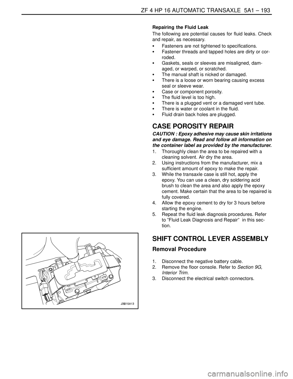
SHIFT CONTROL LEVER ASSEMBLY
Removal Procedure
1. Disconnect the negative battery cable.
2. Remove the floor console. Refer to Section 9G,
Interior Trim.
3. Disconnect the electrical switch connectors.
Page 1544 of 2643
ZF 4 HP 16 AUTOMATIC TRANSAXLE 5A1 – 195
DAEWOO V–121 BL4
4. Connect the electrical switch connectors.
5. Install the floor console. Refer to Section 9G, Interi-
or Trim.
6. Connect the negative battery cable.
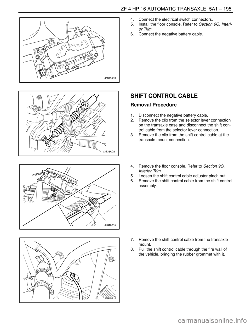
SHIFT CONTROL CABLE
Removal Procedure
1. Disconnect the negative battery cable.
2. Remove the clip from the selector lever connection
on the transaxle case and disconnect the shift con-
trol cable from the selector lever connection.
3. Remove the clip from the shift control cable at the
transaxle mount connection.
4. Remove the floor console. Refer to Section 9G,
Interior Trim.
5. Loosen the shift control cable adjuster pinch nut.
6. Remove the shift control cable from the shift control
assembly.
7. Remove the shift control cable from the transaxle
mount.
8. Pull the shift control cable through the fire wall of
the vehicle, bringing the rubber grommet with it.
Page 1545 of 2643
5A1 – 196IZF 4 HP 16 AUTOMATIC TRANSAXLE
DAEWOO V–121 BL4
Installation Procedure
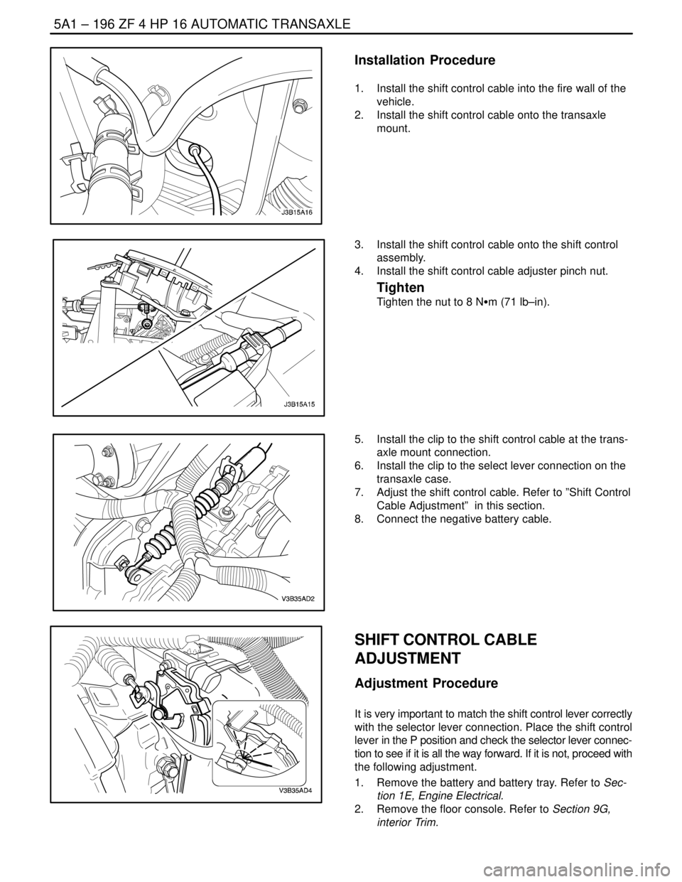
1. Install the shift control cable into the fire wall of the
vehicle.
2. Install the shift control cable onto the transaxle
mount.
3. Install the shift control cable onto the shift control
assembly.
4. Install the shift control cable adjuster pinch nut.
Tighten
Tighten the nut to 8 NSm (71 lb–in).
5. Install the clip to the shift control cable at the trans-
axle mount connection.
6. Install the clip to the select lever connection on the
transaxle case.
7. Adjust the shift control cable. Refer to ”Shift Control
Cable Adjustment” in this section.
8. Connect the negative battery cable.
SHIFT CONTROL CABLE
ADJUSTMENT
Adjustment Procedure
It is very important to match the shift control lever correctly
with the selector lever connection. Place the shift control
lever in the P position and check the selector lever connec-
tion to see if it is all the way forward. If it is not, proceed with
the following adjustment.
1. Remove the battery and battery tray. Refer to Sec-
tion 1E, Engine Electrical.
2. Remove the floor console. Refer to Section 9G,
interior Trim.
Page 1689 of 2643
AISIN AUTOMATIC TRANSAXLE 5A2 – 99
DAEWOO V–121 BL4
FLUID COOLER FLUSHING
Flushing Procedure
1. Drain the fluid from the transaxle and refill the
transaxle with new transaxle fluid. Refer to ”Fluid
Drain Procedure” in this section.
2. Let the engine idle for 5 minutes.
3. Drain the fluid from the transaxle and refill the
transaxle with new transaxle fluid. Refer to ”Fluid
Drain Procedure” in this section.
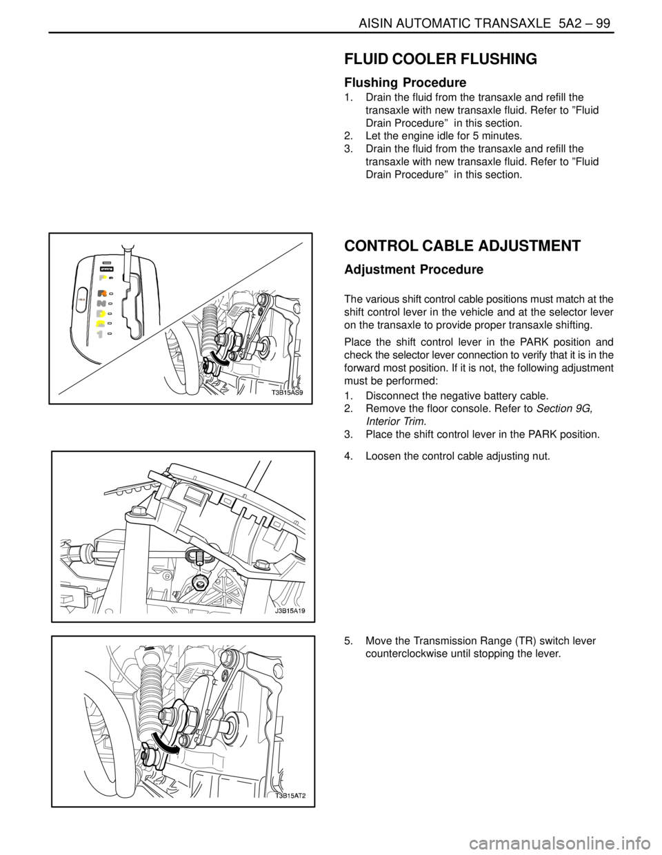
CONTROL CABLE ADJUSTMENT
Adjustment Procedure
The various shift control cable positions must match at the
shift control lever in the vehicle and at the selector lever
on the transaxle to provide proper transaxle shifting.
Place the shift control lever in the PARK position and
check the selector lever connection to verify that it is in the
forward most position. If it is not, the following adjustment
must be performed:
1. Disconnect the negative battery cable.
2. Remove the floor console. Refer to Section 9G,
Interior Trim.
3. Place the shift control lever in the PARK position.
4. Loosen the control cable adjusting nut.
5. Move the Transmission Range (TR) switch lever
counterclockwise until stopping the lever.
Page 1690 of 2643
5A2 – 100IAISIN AUTOMATIC TRANSAXLE
DAEWOO V–121 BL4
6. Pull the shift control cable until it is tight and tighten
the control cable adjusting nut.
Tighten
Tighten the control cable adjusting nut to 8 NSm (71
Ib–in).
7. Install the floor console. Refer to Section 9G, Interi-
or Trim.
8. Connect the negative battery cable.
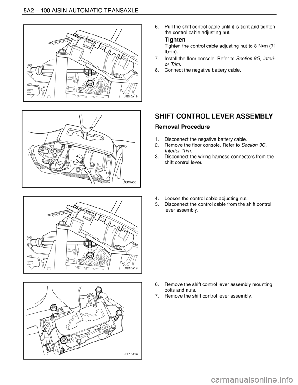
SHIFT CONTROL LEVER ASSEMBLY
Removal Procedure
1. Disconnect the negative battery cable.
2. Remove the floor console. Refer to Section 9G,
Interior Trim.
3. Disconnect the wiring harness connectors from the
shift control lever.
4. Loosen the control cable adjusting nut.
5. Disconnect the control cable from the shift control
lever assembly.
6. Remove the shift control lever assembly mounting
bolts and nuts.
7. Remove the shift control lever assembly.
Page 1694 of 2643
5A2 – 104IAISIN AUTOMATIC TRANSAXLE
DAEWOO V–121 BL4
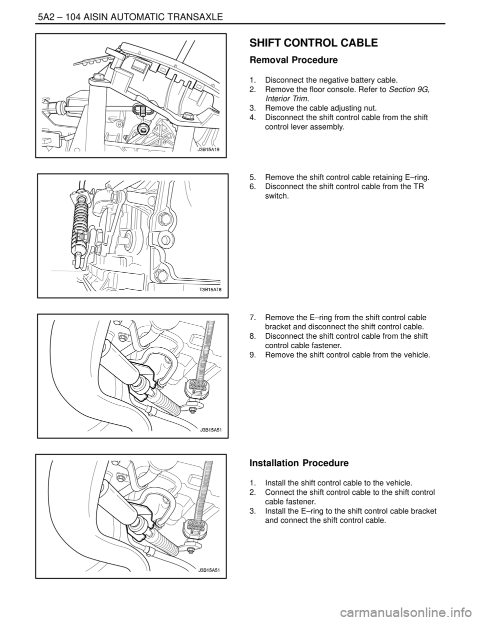
SHIFT CONTROL CABLE
Removal Procedure
1. Disconnect the negative battery cable.
2. Remove the floor console. Refer to Section 9G,
Interior Trim.
3. Remove the cable adjusting nut.
4. Disconnect the shift control cable from the shift
control lever assembly.
5. Remove the shift control cable retaining E–ring.
6. Disconnect the shift control cable from the TR
switch.
7. Remove the E–ring from the shift control cable
bracket and disconnect the shift control cable.
8. Disconnect the shift control cable from the shift
control cable fastener.
9. Remove the shift control cable from the vehicle.
Installation Procedure
1. Install the shift control cable to the vehicle.
2. Connect the shift control cable to the shift control
cable fastener.
3. Install the E–ring to the shift control cable bracket
and connect the shift control cable.
Page 1695 of 2643
AISIN AUTOMATIC TRANSAXLE 5A2 – 105
DAEWOO V–121 BL4
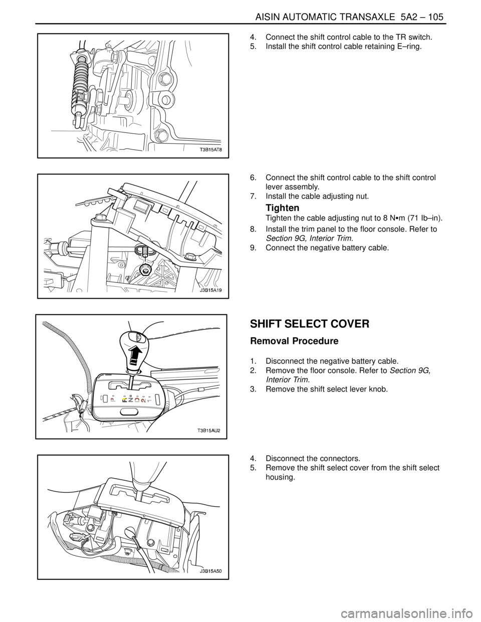
4. Connect the shift control cable to the TR switch.
5. Install the shift control cable retaining E–ring.
6. Connect the shift control cable to the shift control
lever assembly.
7. Install the cable adjusting nut.
Tighten
Tighten the cable adjusting nut to 8 NSm (71 Ib–in).
8. Install the trim panel to the floor console. Refer to
Section 9G, Interior Trim.
9. Connect the negative battery cable.
SHIFT SELECT COVER
Removal Procedure
1. Disconnect the negative battery cable.
2. Remove the floor console. Refer to Section 9G,
Interior Trim.
3. Remove the shift select lever knob.
4. Disconnect the connectors.
5. Remove the shift select cover from the shift select
housing.