Page 1024 of 2643
 Action
16Check for a short to ground in the wiring between the
instrument cluster terminal A19(B15) and the EBCM
connector terminal 21.")
4A – 8IHYDRAULIC BRAKES
DAEWOO V–121 BL4
StepNo Yes Value(s) Action
16Check for a short to ground in the wiring between the
instrument cluster terminal A19(B15) and the EBCM
connector terminal 21.
Is the problem found?–Go to Step 17Go to Step 18
17Repair the wiring as needed.
Is the repair complete?–System OK–
18Check the brake lamp after doing each of the follow-
ing functions:
S Apply the parking brake.
S Remove the cap from the brake fluid reservoir.
S On vehicles equipped with ABS, command the
lamp on using a scan tool.
Does the brake warning lamp operate for all of these
conditions?–System OKGo to Step 19
19When the operations listed in step 18 were per-
formed, the brake warning lamp did not function.
Did the brake warning lamp fail to light for all of the
operations listed in step 18?–Go to Step 20Go to Step 27
201. Turn the ignition OFF.
2. Inspect the kick panel fuse F4.
Is the fuse OK?–Go to Step 22Go to Step 21
21Replace the fuse.
Is the repair complete?–System OK–
22Inspect the brake warning lamp bulb.
Is the bulb OK?–Go to Step 24Go to Step 23
23Replace the bulb.
Is the repair complete?–System OK–
241. Disconnect the instrument cluster connector.
2. Turn the ignition ON.
3. Measure the voltage at the instrument cluster
connector terminal A19(B15).
Does the voltage measure within the value speci-
fied?11–14 vGo to Step 25Go to Step 26
251. Turn the ignition OFF.
2. Repair the open in the instrument cluster.
Is the repair complete?–System OK–
261. Turn the ignition OFF.
2. Repair the open in the wiring between the in-
strument cluster connector terminal A19(B15)
and the ignition switch.
Is the repair complete?–System OK–
27Apply the parking brake again.
Does the parking brake warning lamp operate with
the parking brake applied?–Go to Step 28Go to Step 30
28Remove the brake fluid reservoir cap.
Does the parking brake warning lamp operate with
the cap from the brake fluid reservoir removed?–Go to Step 29Go to Step 32
29Check for an open between the instrument cluster
connector terminal A1 and the EBCM connector ter-
minal 21.
Is the problem found?–Go to Step 17Go to Step 13
Page 1033 of 2643
HYDRAULIC BRAKES 4A – 17
DAEWOO V–121 BL4
GENERAL DESCRIPTION
AND SYSTEM OPERATION
WARNING LAMP OPERATION
This brake system uses a BRAKE warning lamp located
in the instrument panel cluster. When the ignition switch
is in the START position, the BRAKE warning lamp should
illuminate. It should go off when the ignition switch returns
to the ON position.The following conditions will activate the BRAKE warning
lamp:
S The lamp should be on whenever the parking brake
is applied and the ignition switch is in the ON posi-
tion.
S A low fluid level in the master cylinder will turn the
BRAKE lamp on.
Page 1155 of 2643

PARKING BRAKE 4G – 3
DAEWOO V–121 BL4
7. Inspect and replace any parts of doubtful strength
or quality. This can be shown by discoloration from
heat or stress.
8. Using a vernier caliper, adjust the shoe assembly to
167.6 to 167.8 mm (6.60 to 6.61 inches) by turning
the adjuster nut clockwise to increase the diameter.
Measure the shoe assembly diameter as closely as
possible to the center of the lining material.
9. Inspect and install the rotors and calipers. Refer to
Section 4E1, Rear Disc Brakes.
10. Install the parking brake cable to the backplate le-
ver on each side of the vehicle.
11. In the vehicle cabin, pull on the parking brake han-
dle. Stop after hearing two clicks.
12. Turn the rear wheel by hand until the wheel begins
to drag.
13. Release the parking brake.
14. Turn the rear wheel by hand to check the drag. Re-
adjust the cable, if necessary.
15. Repeat the process for the other rear wheel.
16. Lower the vehicle.
PARKING BRAKE LEVER
Removal Procedure
1. Release the parking brake.
2. Remove the parking brake/gearshift console hood.
Refer to Section 9G, Interior Trim.
3. Measure the thread length from the end of the pull
rod to the hex nut.
4. Remove the hex nut.
5. Remove the parking brake warning lamp switch.
Notice : The parking brake switch should be replaced if
the BRAKE warning light in the instrument panel cluster
did not glow when the parking brake was applied with the
ignition switch ON.
Page 1161 of 2643
PARKING BRAKE 4G – 9
DAEWOO V–121 BL4
GENERAL DESCRIPTION
AND SYSTEM OPERATION
PARKING BRAKE
This braking system uses a BRAKE warning light located
in the instrument panel cluster. When the ignition switch
is in the START position, the BRAKE warning light shouldglow and go OFF when the the ignition switch returns to
the RUN position. Whenever the parking brake is applied
and the ignition switch is ON, the BRAKE warning light
should glow.
When the brake is firmly applied, the parking brake should
hold the vehicle with ample pedal travel remaining. Check
for frayed cables, rust, etc. or any condition that many in-
hibit present (or future) free movement of the parking
brake lever assembly.
Page 1216 of 2643
5–56WELECTRICAL WIRING DIAGRAMS
6. TCM (TRANSMISSION CONTROL MODULE) : SIRIUS D4
1) POWER SUPPLY, GROUND, PNP SWITCH, CLUSTER & ECM CIRCUIT : NOTCH BACK
a. CONNECTOR INFORMATION
CONNECTOR(NO.)
(PIN NO. COLOR)
CONNECTING, WIRING HARNESSCONNECTOR POSITION
C105 (4 Pin, White)Body � Engine Fuse BlockEngine Fuse Block
C108 (24 Pin, Black)Body � EngineLeft Engine Fuse Block
C201 (76 Pin, Black)I.P � I.P Fuse BlockI.P Fuse Block
C202 (89 Pin, White)I.P � BodyLeft CO–Driver Leg Room
C206 (22 Pin, White)I.P � TCMUpper Driver Leg Room
C401 (8 Pin, White)Trunk � BodyInside Right Trunk Side Cover
G201I.PLeft I.P Fuse Block
G401TrunkCenter Trunk Lower Back Panel
b. CONNECTOR IDENTIFICATION SYMBOL & PIN NUMBER POSITION
J3B1P074
Page 1254 of 2643
5–94WELECTRICAL WIRING DIAGRAMS
12. FRONT & REAR FOG LAMP CIRCUIT
1) NOTCH BACK
a. CONNECTOR INFORMATION
CONNECTOR(NO.)
(PIN NO. COLOR)
CONNECTING, WIRING HARNESSCONNECTOR POSITION
C101 (21 Pin, White)Body � Engine Fuse BlockEngine Fuse Block
C104 (24 Pin, White)Front � Engine Fuse BlockEngine Fuse Block
C105 (4 Pin, White)Body � Engine Fuse BlockEngine Fuse Block
C201 (76 Pin, Black)I.P � I.P Fuse BlockI.P Fuse Block
C202 (89 Pin, White)I.P � BodyLeft CO–Driver Leg Room
C401 (8 Pin, White)Trunk � BodyInside Right Trunk Side Cover
S202 (Black)I.PBehind Cluster
S204 (Magenta)I.PBehind Audio Mounting
G101FrontBehind Left Head Lamp
G102FrontBehind Right Head Lamp
G201I.PLeft I.P Fuse Block
G401TrunkCenter Trunk Lower Back Panel
b. CONNECTOR IDENTIFICATION SYMBOL & PIN NUMBER POSITION
Page 1256 of 2643
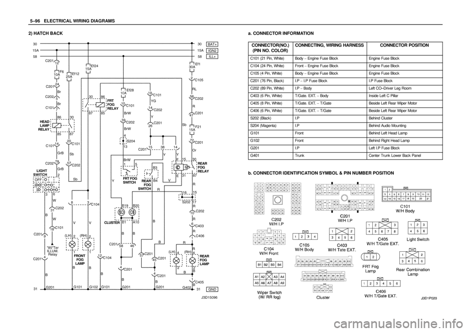
5–96WELECTRICAL WIRING DIAGRAMS
2) HATCH BACKa. CONNECTOR INFORMATION
CONNECTOR(NO.)
(PIN NO. COLOR)
CONNECTING, WIRING HARNESSCONNECTOR POSITION
C101 (21 Pin, White)Body � Engine Fuse BlockEngine Fuse Block
C104 (24 Pin, White)Front � Engine Fuse BlockEngine Fuse Block
C105 (4 Pin, White)Body � Engine Fuse BlockEngine Fuse Block
C201 (76 Pin, Black)I.P � I.P Fuse BlockI.P Fuse Block
C202 (89 Pin, White)I.P � BodyLeft CO–Driver Leg Room
C403 (6 Pin, White)T/Gate. EXT. � BodyInside Left C Pillar
C405 (8 Pin, White)T/Gate. EXT. � T/GateBeside Left Rear Wiper Motor
C406 (6 Pin, White)T/Gate. EXT. � T/GateBeside Left Rear Wiper Motor
S202 (Black)I.PBehind Cluster
S204 (Magenta)I.PBehind Audio Mounting
G101FrontBehind Left Head Lamp
G102FrontBehind Right Head Lamp
G201I.PLeft I.P Fuse Block
G401TrunkCenter Trunk Lower Back Panel
b. CONNECTOR IDENTIFICATION SYMBOL & PIN NUMBER POSITION
Page 1258 of 2643
5–98WELECTRICAL WIRING DIAGRAMS
13. HAZARD & TURN SIGNAL LAMP CIRCUIT
1) NOTCH BACK
a. CONNECTOR INFORMATION
CONNECTOR(NO.)
(PIN NO. COLOR)
CONNECTING, WIRING HARNESSCONNECTOR POSITION
C101 (21 Pin, White)Body � Engine Fuse BlockEngine Fuse Block
C105 (4 Pin, White)Body � Engine Fuse BlockEngine Fuse Block
C113 (16 Pin, Black)Body � FrontBehind ECM Bracket
C201 (76 Pin, Black)I.P � I.P Fuse BlockI.P Fuse Block
C202 (89 Pin, White)I.P � BodyLeft CO–Driver Leg Room
C401 (8 Pin, White)Trunk � BodyInside Right Trunk Side Cover
S202 (Black)I.PBehind Cluster
S203 (Red)I.PBehind Audio Mounting
S204 (Magenta)I.PBehind Audio Mounting
S302 (Brown)BodyLeft CO–Driver Leg Room
G101FrontBehind Left Head Lamp
G102FrontBehind Right Head Lamp
G201I.PLeft I.P Fuse Block
G203I.PBehind Left Audio Bracket
G303BodyBelow Left CO–Driver Leg Room
G401TrunkCenter Trunk Lower Back Panel
b. CONNECTOR IDENTIFICATION SYMBOL & PIN NUMBER POSITION


 : SIRIUS D4
1) POWER SUPPLY, GROUND, PNP SWITCH, CLUSTER & ECM CIRCUIT : NOTCH BACK
a. CONNECTOR INFORMATION
CONNECTOR(NO.)
(PIN")
 NOTCH BACK
a. CONNECTOR INFORMATION
CONNECTOR(NO.)
(PIN NO. COLOR)
CONNECTING, WIRING HARNESSCONNECTOR POSITION
C101 (21 Pin, Whi")
 NOTCH BACK
a. CONNECTOR INFORMATION
CONNECTOR(NO.)
(PIN NO. COLOR)
CONNECTING, WIRING HARNESSCONNECTOR POSITION
C101 (21 Pin,")