Page 1344 of 2643
5–184WELECTRICAL WIRING DIAGRAMS
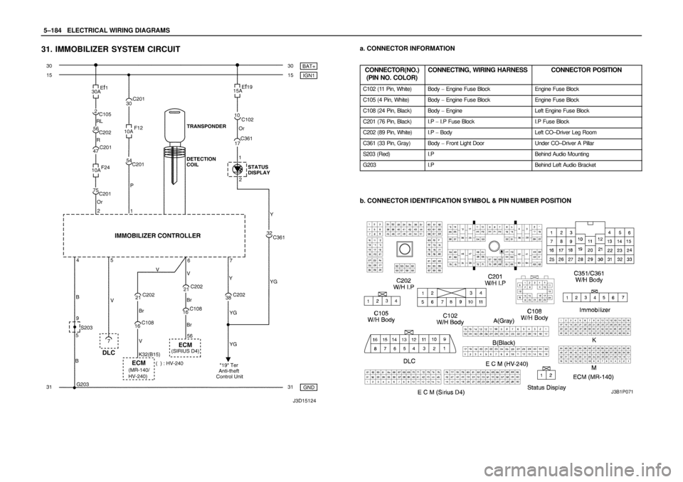
31. IMMOBILIZER SYSTEM CIRCUITa. CONNECTOR INFORMATION
CONNECTOR(NO.)
(PIN NO. COLOR)
CONNECTING, WIRING HARNESSCONNECTOR POSITION
C102 (11 Pin, White)Body � Engine Fuse BlockEngine Fuse Block
C105 (4 Pin, White)Body � Engine Fuse BlockEngine Fuse Block
C108 (24 Pin, Black)Body � EngineLeft Engine Fuse Block
C201 (76 Pin, Black)I.P � I.P Fuse BlockI.P Fuse Block
C202 (89 Pin, White)I.P � BodyLeft CO–Driver Leg Room
C361 (33 Pin, Gray)Body � Front Light DoorUnder CO–Driver A Pillar
S203 (Red)I.PBehind Audio Mounting
G203I.PBehind Left Audio Bracket
b. CONNECTOR IDENTIFICATION SYMBOL & PIN NUMBER POSITION
J3B1P071
Page 1346 of 2643
 NOTCH BACK
a. CONNECTOR INFORMATION
CONNECTOR(NO.)
(PIN NO. COLOR)
CONNECTING, WIRING HARNESSCONNECTOR POSITION
C102 (11 Pin")
5–186WELECTRICAL WIRING DIAGRAMS
32. ANTI THEFT CONTROL SYSTEM CIRCUIT
1) NOTCH BACK
a. CONNECTOR INFORMATION
CONNECTOR(NO.)
(PIN NO. COLOR)
CONNECTING, WIRING HARNESSCONNECTOR POSITION
C102 (11 Pin, White)Body � Engine Fuse BlockEngine Fuse Block
C104 (24 Pin, White)Front � Engine Fuse BlockEngine Fuse Block
C105 (4 Pin, White)Body � Engine Fuse BlockEngine Fuse Block
C113 (16 Pin, Black)Body � FrontBehind ECM Bracket
C201 (76 Pin, Black)I.P � I.P Fuse BlockI.P Fuse Block
C202 (89 Pin, White)I.P � BodyLeft CO–Driver Leg Room
C351 (33 Pin, Gray)Body � Front Light DoorUnder CO–Driver A Pillar
C361 (33 Pin, Gray)Body � Front Right DoorUnder Driver A Pillar
C402 (8 Pin, White)Trunk LID � BodyInside Right Trunk Side Cover
S202 (Black)I.PBehind Cluster
S301 (Blue)BodyLeft CO–Driver Leg Room
S302 (Brown)BodyLeft CO–Driver Leg Room
G301BodyBelow Driver Cross Member Floor Panel
G302BodyBelow Left C Pillar
G303BodyBelow Left CO–Driver Leg Room
b. CONNECTOR IDENTIFICATION SYMBOL & PIN NUMBER POSITION
Page 1348 of 2643
 HATCH BACKa. CONNECTOR INFORMATION
CONNECTOR(NO.)
(PIN NO. COLOR)
CONNECTING, WIRING HARNESSCONNECTOR POSITION
C102 (11 Pin, White)Body � Engine Fuse BlockEngine")
5–188WELECTRICAL WIRING DIAGRAMS
2) HATCH BACKa. CONNECTOR INFORMATION
CONNECTOR(NO.)
(PIN NO. COLOR)
CONNECTING, WIRING HARNESSCONNECTOR POSITION
C102 (11 Pin, White)Body � Engine Fuse BlockEngine Fuse Block
C104 (24 Pin, White)Front � Engine Fuse BlockEngine Fuse Block
C105 (4 Pin, White)Body � Engine Fuse BlockEngine Fuse Block
C113 (16 Pin, Black)Body � FrontBehind ECM Bracket
C201 (76 Pin, Black)I.P � I.P Fuse BlockI.P Fuse Block
C202 (89 Pin, White)I.P � BodyLeft CO–Driver Leg Room
C351 (33 Pin, Gray)Body � Front Light DoorUnder CO–Driver A Pillar
C361 (33 Pin, Gray)Body � Front Right DoorUnder Driver A Pillar
C404 (8 Pin, White)T/Gate. EXT. � BodyInside Left C Pillar
C405 (8 Pin, White)T/Gate. EXT. � T/GateBeside Left Rear Wiper Motor
C406 (6 Pin, White)T/Gate. EXT. � T/GateBeside Left Rear Wiper Motor
S202 (Black)I.PBehind Cluster
S301 (Blue)BodyLeft CO–Driver Leg Room
S302 (Brown)BodyLeft CO–Driver Leg Room
G301BodyBelow Driver Cross Member Floor Panel
G302BodyBelow Left C Pillar
G303BodyBelow Left CO–Driver Leg Room
G402T/Gate. EXT.Inside Driver C Pillar
b. CONNECTOR IDENTIFICATION SYMBOL & PIN NUMBER POSITION
Page 2069 of 2643
 Action
20Repair the problem in circuit (Violet).
Is the repair complete")
7D – 14IAUTOMATIC TEMPERATURE CONTROL HEATING, VENTILATION, AND AIR CONDITIONING SYSTEM
DAEWOO V–121 BL4
StepNo Yes Value(s) Action
20Repair the problem in circuit (Violet).
Is the repair complete?–System OK–
21Measure the resistance of circuit (Black) from termi-
nal 3 of the power transistor connector to ground.
Does the resistance match the specified value?� 0 ΩGo to Step 23Go to Step 22
221. Trace circuit (Black) from terminal 3 of the
power transistor connector and terminal 87 of
the Max HI relay to ground G203.
2. Repair any problem found in the wiring, ground
G203.
Is the repair complete?–System OK–
23Replace the ATC controller.
the repair complete?–System OK–
MODE CONTROL DO NOT WORK
Refer to ”A/C Blower and Motor Controls Diagram”for the electrical schematic diagram of the circuits described in this
procedure.
Mode Controls Do Not Work
StepActionValue(s)YesNo
1Measure the voltage between terminal 4 and termi-
nal 5 of the mode motor.
Is the voltage within the specified value for motor?11–14 vGo to Step 3Go to Step 2
21. Check fuse F7?
2. Check the connector and circuit (Brown and
Black) for any wiring or terminal problems.
3. Repair any problems found.
Is the repair complete?–System OK–
31. Using the Motor Control Table, measure the
voltages at the specified terminals of the speci-
fied motor connectors.
2. Change the mode settings and observe the
voltage changes.
Are the voltages as specified?See the ”Motor
Control Table”Go to Step 4Go to Step 5
4Replace the motor that does not operate properly.
Is the repair complete?–System OK–
51. Using the Motor Control Table, measure the
voltages at the specified terminals of the speci-
fied controller connectors.
2. Change the mode settings and observe the
voltage changes.
Are the voltages as specified?See the ”Motor
Control Table”Go to Step 6Go to Step 7
61. Check the wiring harness and connectors be-
tween the controller and the motor that is not
performing properly.
2. Repair or replace the wiring harness or the de-
fective terminal.
Is the repair complete?–System OK–
7Check the connector at the controller.
Is there a defective terminal?–Go to Step 8Go to Step 9
Page 2207 of 2643

SECTION : 9A
BODY WIRING SYSTEM
CAUTION : Disconnect the negative battery cable before removing or installing any electrical unit or when a tool
or equipment could easily come in contact with exposed electrical terminals. Disconnecting this cable will help
prevent personal injury and damage to the vehicle. The ignition must also be in LOCK unless otherwise noted.
TABLE OF CONTENTS
SCHEMATIC AND ROUTING DIAGRAMS9A–1 . . . . .
Wire Color Chart 9A–1. . . . . . . . . . . . . . . . . . . . . . . . . . .
Power Distribution Schematic 9A–3. . . . . . . . . . . . . . .
Fuse Block Locator (Engine) 9A–12. . . . . . . . . . . . . . .
Fuse Block Locator (Passenger Compartment) 9A–12
Fuse Chart 9A–13. . . . . . . . . . . . . . . . . . . . . . . . . . . . . . Front Harness Routing 9A–15. . . . . . . . . . . . . . . . . . . .
Rear Harness Routing 9A–16. . . . . . . . . . . . . . . . . . . . .
Hatchback Rear Harness Routing 9A–17. . . . . . . . . . .
Floor Harness Routing 9A–18. . . . . . . . . . . . . . . . . . . .
Instrument Harness Routing 9A–19. . . . . . . . . . . . . . . .
Door Harness Routing 9A–20. . . . . . . . . . . . . . . . . . . . .
SCHEMATIC AND ROUTING DIAGRAMS
WIRE COLOR CHART
Wire ColorAbbreviation On Schematic
GreenDK GRN
Light GreenLT GRN
BlueDK BLU
BrownBRN
OrangeORN
YellowYEL
GreyGRY
Sky BlueLT BLU
RedRED
BlackBLK
PinkPNK
WhiteWHT
PurplePPL