2004 CHRYSLER VOYAGER headlamp
[x] Cancel search: headlampPage 1245 of 2585

SPLICE NUMBER LOCATION FIG.
S126 In Right Headlamp Leveling Assembly N/S
S127 (Diesel) In T/O for Engine Starter Motor N/S
S128 (Diesel) Near T/O for Engine Starter Motor N/S
S129 (Diesel) Near T/O for Battery (+) N/S
S130 (Diesel) Near T/O for Battery (+) N/S
S131 Near T/O for Transmission Control Module 11
S131 (3.3L/3.8L) Near T/O for C110 N/S
S132 (Diesel) Near T/O for Battery (+) N/S
S134 (Diesel) IN T/O for Engine Control Module N/S
S135 (Diesel) Near T/O for Glow Plug No.2 N/S
S136 (Diesel) In T/O for Radiator Fan Relays 2
S137 (Diesel) Above Starter 15
S138 (Diesel) Between T/O for Radiator Fan No.2 and T/O for G102 N/S
S139 (Diesel) Between T/O for Engine Starter Motor and T/O for
Engine Control Module C115, 16
S141 (2.4L) Near T/O for C110 11
S141 (Diesel) Near T/O for G100 N/S
S141 (3.3L/3.8L) Near T/O for Powertrain Control Module N/S
S142 (3.3L/3.8L) Near T/O for A/C Compressor Clutch 18
S144 (Diesel) Between T/O for Battery Temperature Sensor and T/O
for C103N/S
S148 (Diesel) Near T/O for Engine Starter Motor 5
S150 (Diesel) Between T/O for Battery Temperature Sensor and T/O
for C103N/S
S151 (Diesel) Near T/O for Radiator Fan Relays 2
S152 (Diesel) Near T/O for Radiator Fan No.1 N/S
S157 (Diesel) Near T/O for Glow Plug No.4 15
S177 In Right Headlamp Wiring Assembly N/S
S179 In Left Headlamp Wiring Assembly N/S
S187 (Diesel) In T/O for Engine Control Module C1 N/S
S188 (Diesel) Near T/O for Radiator Fan Relays 2
S201 In T/O to Instrument Panel Speaker 20, 26
S202 Near T/O for Instrument Panel Switch Bank 20, 26
S203 Near T/O for Instrument Panel Switch Bank 26
S204 Near T/O to Instrument Panel Speaker 20, 26
S205 Near T/O for C201 N/S
S206 Near T/O for Instrument Cluster 20
S207 Near T/O for A/C Heater Control 20, 26
S208 (RHD) Between T/O for Antenna Connector and T/O for Front
Cigar Lighter26
S209 Near T/O for Evaporator Temperature Sensor N/S
S210 (RHD) Near T/O for C203 26
S211 In Steering Column Wiring Assembly N/S
8W - 91 - 14 8W-91 CONNECTOR/GROUND/SPLICE LOCATIONRS
CONNECTOR/GROUND/SPLICE LOCATION (Continued)
Page 1248 of 2585
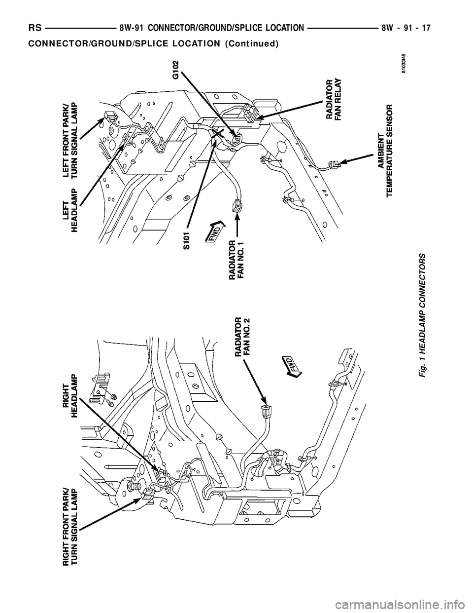
Fig. 1 HEADLAMP CONNECTORS
RS8W-91 CONNECTOR/GROUND/SPLICE LOCATION8W-91-17
CONNECTOR/GROUND/SPLICE LOCATION (Continued)
Page 1496 of 2585
FRAME & BUMPERS
TABLE OF CONTENTS
page page
BUMPERS
SPECIFICATIONS - TORQUE...............1
FRONT FASCIA
REMOVAL.............................1
INSTALLATION..........................1
FRONT BUMPER REINFORCEMENT
REMOVAL.............................2
INSTALLATION..........................2
REAR FASCIA
REMOVAL.............................2
INSTALLATION..........................2
REAR BUMPER REINFORCEMENT
REMOVAL.............................3
INSTALLATION..........................3
REAR FASCIA - SCUFF PAD
REMOVAL.............................3INSTALLATION..........................4
FRAME
SPECIFICATIONS
FRAME DIMENSIONS...................4
SPECIFICATIONS - TORQUE.............9
FRONT CRADLE CROSSMEMBER
DESCRIPTION
DESCRIPTION - FRONT CRADLE
CROSSMEMBER.......................9
DESCRIPTION - FRONT CRADLE
CROSSMEMBER THREAD REPAIR.........9
REMOVAL.............................10
INSTALLATION.........................11
FRONT CROSSMEMBER MOUNT BUSHINGS
REMOVAL.............................12
INSTALLATION.........................12
BUMPERS
SPECIFICATIONS - TORQUE
DESCRIPTION N´m Ft. Lbs. In. Lbs.
Front bumper reinforcement attaching nut 54 40 Ð
Rear bumper reinforcement attaching nut 27 20 Ð
FRONT FASCIA
REMOVAL
(1) Release hood latch and open hood.
(2) Remove the headlamp assemblies (Refer to 8 -
ELECTRICAL/LAMPS/LIGHTING - EXTERIOR/
HEADLAMP - REMOVAL).
(3) Hoist vehicle and support with safety stands.
(4) Remove the five bolts attaching bottom of fas-
cia/air dam to radiator closure panel.
(5) Remove front wheels.
(6) Remove front wheelhouse splash shields fasten-
ers as necessary to gain access to bolts attaching
front fascia to fender. (Refer to 23 - BODY/EXTERI-
OR/ WHEELHOUSE SPLASH SHIELD -
REMOVAL).
(7) Remove the two bolts and two nuts attaching
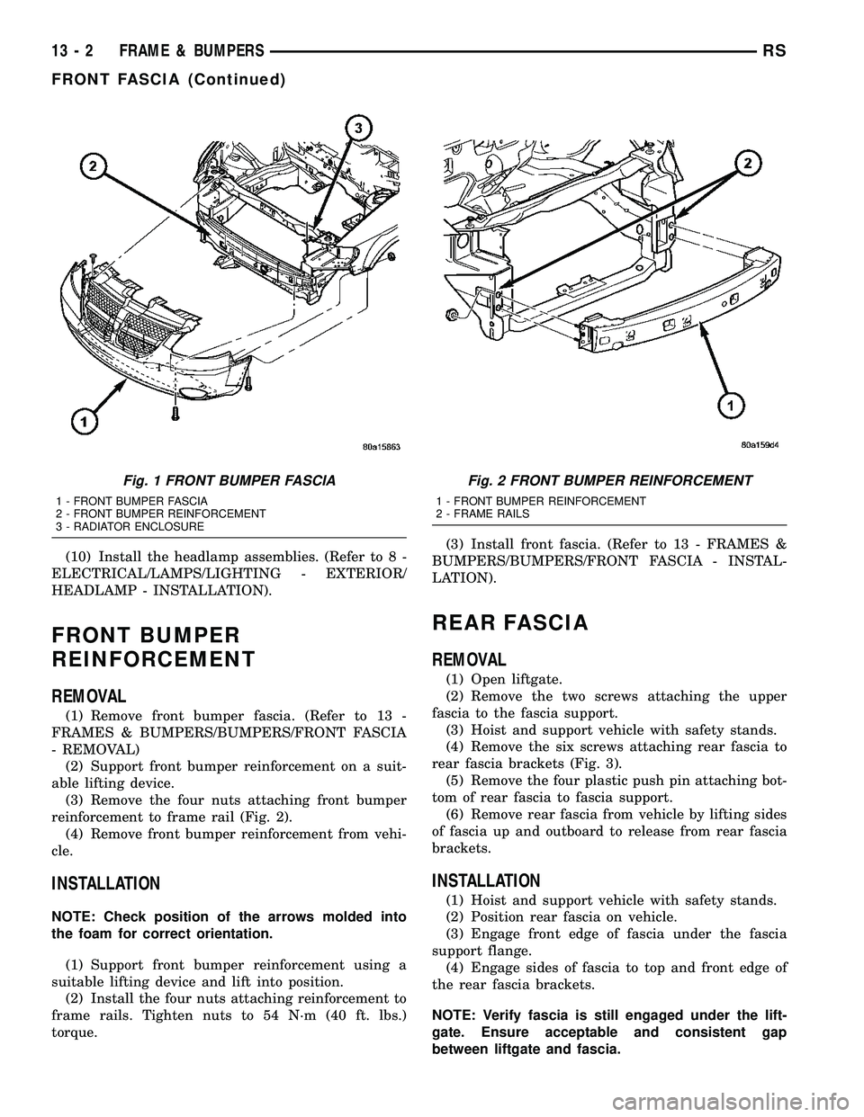
fascia to the front fenders (Fig. 1).
(8) Disconnect fog lamp wire connectors, if neces-
sary.
(9) Lower vehicle.(10) Remove two bolts attaching the upper grille
support to the headlamp mounting panel at each side
of the grille.
(11) Remove bumper fascia from vehicle.
INSTALLATION
(1) Position front bumper fascia on vehicle.
(2) Install the two bolts attaching fascia to head-
lamp mounting panel at each side of grille.
(3) Hoist vehicle and support with safety stands.
(4) Install the two bolts and two nuts attaching
fascia to the front fenders (Fig. 1). The fascia should
be flush to fender.
(5) Install front wheelhouse splash shields fasten-
ers. (Refer to 23 - BODY/EXTERIOR/ WHEEL-
HOUSE SPLASH SHIELD - INSTALLATION).
(6) Install front wheels.
(7) Connect fog lamp wire connectors, if necessary.
(8) Install the five bolts attaching bottom of fascia
to radiator closure panel.
(9) Lower the vehicle.
RSFRAME & BUMPERS13-1
Page 1497 of 2585
(10) Install the headlamp assemblies. (Refer to 8 -
ELECTRICAL/LAMPS/LIGHTING - EXTERIOR/
HEADLAMP - INSTALLATION).
FRONT BUMPER
REINFORCEMENT
REMOVAL
(1) Remove front bumper fascia. (Refer to 13 -
FRAMES & BUMPERS/BUMPERS/FRONT FASCIA
- REMOVAL)
(2) Support front bumper reinforcement on a suit-
able lifting device.
(3) Remove the four nuts attaching front bumper
reinforcement to frame rail (Fig. 2).
(4) Remove front bumper reinforcement from vehi-
cle.
INSTALLATION
NOTE: Check position of the arrows molded into
the foam for correct orientation.
(1) Support front bumper reinforcement using a
suitable lifting device and lift into position.
(2) Install the four nuts attaching reinforcement to
frame rails. Tighten nuts to 54 N´m (40 ft. lbs.)
torque.(3) Install front fascia. (Refer to 13 - FRAMES &
BUMPERS/BUMPERS/FRONT FASCIA - INSTAL-
LATION).
REAR FASCIA
REMOVAL
(1) Open liftgate.
(2) Remove the two screws attaching the upper
fascia to the fascia support.
(3) Hoist and support vehicle with safety stands.
(4) Remove the six screws attaching rear fascia to
rear fascia brackets (Fig. 3).
(5) Remove the four plastic push pin attaching bot-
tom of rear fascia to fascia support.
(6) Remove rear fascia from vehicle by lifting sides
of fascia up and outboard to release from rear fascia
brackets.
INSTALLATION
(1) Hoist and support vehicle with safety stands.
(2) Position rear fascia on vehicle.
(3) Engage front edge of fascia under the fascia
support flange.
(4) Engage sides of fascia to top and front edge of
the rear fascia brackets.
NOTE: Verify fascia is still engaged under the lift-
gate. Ensure acceptable and consistent gap
between liftgate and fascia.
Fig. 1 FRONT BUMPER FASCIA
1 - FRONT BUMPER FASCIA
2 - FRONT BUMPER REINFORCEMENT
3 - RADIATOR ENCLOSURE
Fig. 2 FRONT BUMPER REINFORCEMENT
1 - FRONT BUMPER REINFORCEMENT
2 - FRAME RAILS
13 - 2 FRAME & BUMPERSRS
FRONT FASCIA (Continued)
Page 2163 of 2585
FRONT FENDER
REMOVAL
(1) Remove headlamp housing. (Refer to 8 - ELEC-
TRICAL/LAMPS/LIGHTING - EXTERIOR/HEAD-
LAMP UNIT - REMOVAL)
(2) Remove mud guard.
(3) Remove inner splash shield.
(4) Remove fender to fascia nuts.
(5) Remove outboard cowl grille/fender bracket
screw.
(6) Remove fender bolt to lower rocker panel.
(7) Remove fender bolt to lower cowl.
(8) Pull fascia away from fender.
(9) Remove bolts attaching fender to upper rail.
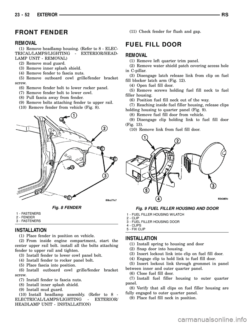
(10) Remove fender from vehicle (Fig. 8).
INSTALLATION
(1) Place fender in position on vehicle.
(2) From inside engine compartment, start the
center upper rail bolt. install all the bolts attaching
fender to upper rail and tighten.
(3) Install fender to lower cowl panel bolt.
(4) Install fender to rocker panel bolt.
(5) Place fascia into position.
(6) Install outboard cowl grille/fender bracket
screw.
(7) Install fender to fascia nuts.
(8) Install inner splash shield.
(9) Install mud guard.
(10) Install headlamp assembly. (Refer to 8 -
ELECTRICAL/LAMPS/LIGHTING - EXTERIOR/
HEADLAMP UNIT - INSTALLATION)(11) Check fender for flush and gap.
FUEL FILL DOOR
REMOVAL
(1) Remove left quarter trim panel.
(2) Remove water shield patch covering access hole
in C-pillar.
(3) Disengage latch release link from clip on fuel
fill blocker latch arm (Fig. 12).
(4) Open fuel fill door.
(5) Remove screws holding fuel fill neck to fuel
filler housing.
(6) Position fuel fill neck out of the way.
(7) Reaching inside fuel filler housing, release clips
holding housing to quarter panel (Fig. 9).
(8) Remove fuel fill door from vehicle.
(9) Disengage clip holding link to fuel fill door
(Fig. 13).
(10) Remove link from fuel fill door.
INSTALLATION
(1) Install spring to housing and door
(2) Snap door into housing.
(3) Insert lockout link into clip on fuel fill door.
(4) Engage clip to hold link to fuel fill door.
(5) Insert lockout link through grommet in panel
between inner and outer quarter panel.
(6) Close fuel fill door.
(7) Install fuel filler housing to outer quarter
panel.
(8) Verify that all clips on fuel filler housing are
fully engaged to outer quarter panel.
(9) Place fuel fill neck in position.
Fig. 8 FENDER
1 - FASTENERS
2 - FENDER
3 - FASTENERS
Fig. 9 FUEL FILLER HOUSING AND DOOR
1 - FUEL FILLER HOUSING W/LATCH
2 - CLIP
3 - FUEL FILLER HOUSING DOOR
4 - CLIPS
5 - FIX CLIP
23 - 52 EXTERIORRS
Page 2182 of 2585
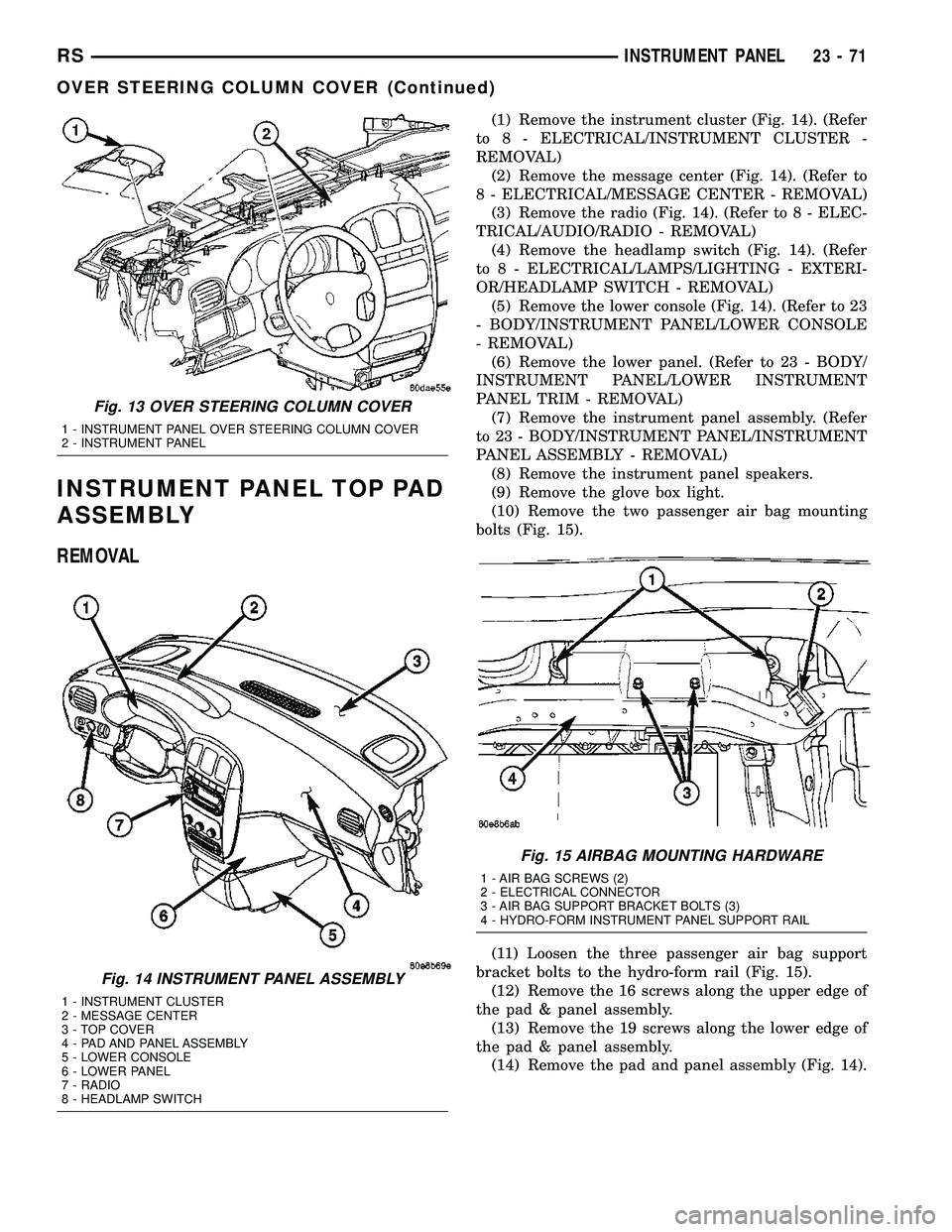
INSTRUMENT PANEL TOP PAD
ASSEMBLY
REMOVAL
(1) Remove the instrument cluster (Fig. 14). (Refer
to 8 - ELECTRICAL/INSTRUMENT CLUSTER -
REMOVAL)
(2) Remove the message center (Fig. 14). (Refer to
8 - ELECTRICAL/MESSAGE CENTER - REMOVAL)
(3) Remove the radio (Fig. 14). (Refer to 8 - ELEC-
TRICAL/AUDIO/RADIO - REMOVAL)
(4) Remove the headlamp switch (Fig. 14). (Refer
to 8 - ELECTRICAL/LAMPS/LIGHTING - EXTERI-
OR/HEADLAMP SWITCH - REMOVAL)
(5) Remove the lower console (Fig. 14). (Refer to 23
- BODY/INSTRUMENT PANEL/LOWER CONSOLE
- REMOVAL)
(6) Remove the lower panel. (Refer to 23 - BODY/
INSTRUMENT PANEL/LOWER INSTRUMENT
PANEL TRIM - REMOVAL)
(7) Remove the instrument panel assembly. (Refer
to 23 - BODY/INSTRUMENT PANEL/INSTRUMENT
PANEL ASSEMBLY - REMOVAL)
(8) Remove the instrument panel speakers.
(9) Remove the glove box light.
(10) Remove the two passenger air bag mounting
bolts (Fig. 15).
(11) Loosen the three passenger air bag support
bracket bolts to the hydro-form rail (Fig. 15).
(12) Remove the 16 screws along the upper edge of
the pad & panel assembly.
(13) Remove the 19 screws along the lower edge of
the pad & panel assembly.
(14) Remove the pad and panel assembly (Fig. 14).
Fig. 13 OVER STEERING COLUMN COVER
1 - INSTRUMENT PANEL OVER STEERING COLUMN COVER
2 - INSTRUMENT PANEL
Fig. 14 INSTRUMENT PANEL ASSEMBLY
1 - INSTRUMENT CLUSTER
2 - MESSAGE CENTER
3 - TOP COVER
4 - PAD AND PANEL ASSEMBLY
5 - LOWER CONSOLE
6 - LOWER PANEL
7 - RADIO
8 - HEADLAMP SWITCH
Fig. 15 AIRBAG MOUNTING HARDWARE
1 - AIR BAG SCREWS (2)
2 - ELECTRICAL CONNECTOR
3 - AIR BAG SUPPORT BRACKET BOLTS (3)
4 - HYDRO-FORM INSTRUMENT PANEL SUPPORT RAIL
RSINSTRUMENT PANEL23-71
OVER STEERING COLUMN COVER (Continued)
Page 2183 of 2585
INSTALLATION
(1) Position the pad & panel assembly onto the
instrument panel support structure.
(2) Install the 19 screws along the lower edge of
the pad & panel assembly.
(3) Install the 16 screws along the upper edge of
the pad & panel assembly.
(4) Install and tighten the two passenger air bag
mounting screws.
(5) Tighten the three passenger air bag support
bracket bolts to the hydro-form tube.
(6) Install the glove box light.
(7) Install the instrument panel speakers.
(8) Install the instrument panel assembly. (Refer
to 23 - BODY/INSTRUMENT PANEL/INSTRUMENT
PANEL ASSEMBLY - INSTALLATION)
(9) Install the lower panel. (Refer to 23 - BODY/
INSTRUMENT PANEL/LOWER INSTRUMENT
PANEL TRIM - INSTALLATION)(10) Install the lower console. (Refer to 23 - BODY/
INSTRUMENT PANEL/LOWER CONSOLE -
INSTALLATION)
(11) Install the headlamp switch. (Refer to 8 -
ELECTRICAL/LAMPS/LIGHTING - EXTERIOR/
HEADLAMP SWITCH - INSTALLATION)
(12) Install the radio. (Refer to 8 - ELECTRICAL/
AUDIO/RADIO - INSTALLATION)
(13) Install the message center. (Refer to 8 -
ELECTRICAL/MESSAGE CENTER - INSTALLA-
TION)
(14) Install the instrument cluster. (Refer to 8 -
ELECTRICAL/INSTRUMENT CLUSTER - INSTAL-
LATION)
23 - 72 INSTRUMENT PANELRS
INSTRUMENT PANEL TOP PAD ASSEMBLY (Continued)
Page 2237 of 2585
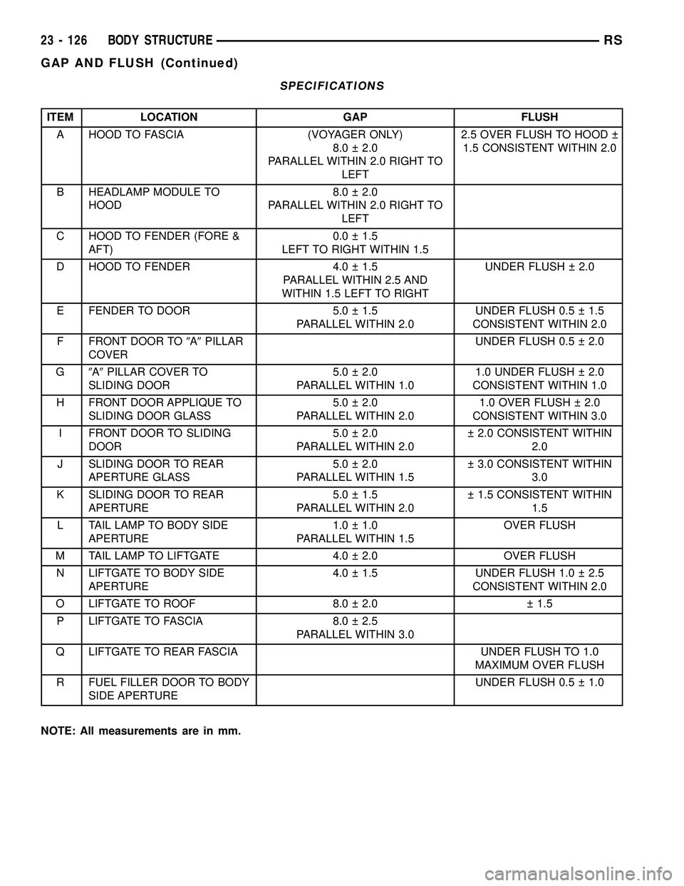
SPECIFICATIONS
ITEM LOCATION GAP FLUSH
A HOOD TO FASCIA (VOYAGER ONLY)
8.0 2.0
PARALLEL WITHIN 2.0 RIGHT TO
LEFT2.5 OVER FLUSH TO HOOD
1.5 CONSISTENT WITHIN 2.0
B HEADLAMP MODULE TO
HOOD8.0 2.0
PARALLEL WITHIN 2.0 RIGHT TO
LEFT
C HOOD TO FENDER (FORE &
AFT)0.0 1.5
LEFT TO RIGHT WITHIN 1.5
D HOOD TO FENDER 4.0 1.5
PARALLEL WITHIN 2.5 AND
WITHIN 1.5 LEFT TO RIGHTUNDER FLUSH 2.0
E FENDER TO DOOR 5.0 1.5
PARALLEL WITHIN 2.0UNDER FLUSH 0.5 1.5
CONSISTENT WITHIN 2.0
F FRONT DOOR TO9A9PILLAR
COVERUNDER FLUSH 0.5 2.0
G9A9PILLAR COVER TO
SLIDING DOOR5.0 2.0
PARALLEL WITHIN 1.01.0 UNDER FLUSH 2.0
CONSISTENT WITHIN 1.0
H FRONT DOOR APPLIQUE TO
SLIDING DOOR GLASS5.0 2.0
PARALLEL WITHIN 2.01.0 OVER FLUSH 2.0
CONSISTENT WITHIN 3.0
I FRONT DOOR TO SLIDING
DOOR5.0 2.0
PARALLEL WITHIN 2.0 2.0 CONSISTENT WITHIN
2.0
J SLIDING DOOR TO REAR
APERTURE GLASS5.0 2.0
PARALLEL WITHIN 1.5 3.0 CONSISTENT WITHIN
3.0
K SLIDING DOOR TO REAR
APERTURE5.0 1.5
PARALLEL WITHIN 2.0 1.5 CONSISTENT WITHIN
1.5
L TAIL LAMP TO BODY SIDE
APERTURE1.0 1.0
PARALLEL WITHIN 1.5OVER FLUSH
M TAIL LAMP TO LIFTGATE 4.0 2.0 OVER FLUSH
N LIFTGATE TO BODY SIDE
APERTURE4.0 1.5 UNDER FLUSH 1.0 2.5
CONSISTENT WITHIN 2.0
O LIFTGATE TO ROOF 8.0 2.0 1.5
P LIFTGATE TO FASCIA 8.0 2.5
PARALLEL WITHIN 3.0
Q LIFTGATE TO REAR FASCIA UNDER FLUSH TO 1.0
MAXIMUM OVER FLUSH
R FUEL FILLER DOOR TO BODY
SIDE APERTUREUNDER FLUSH 0.5 1.0
NOTE: All measurements are in mm.
23 - 126 BODY STRUCTURERS
GAP AND FLUSH (Continued)