2004 CHRYSLER VOYAGER key battery
[x] Cancel search: key batteryPage 1803 of 2585
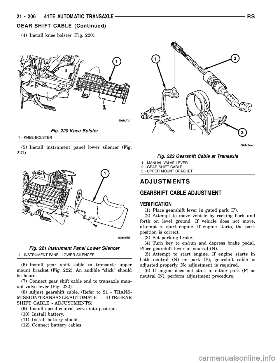
(4) Install knee bolster (Fig. 220).
(5) Install instrument panel lower silencer (Fig.
221).
(6) Install gear shift cable to transaxle upper
mount bracket (Fig. 222). An audible ªclickº should
be heard.
(7) Connect gear shift cable end to transaxle man-
ual valve lever (Fig. 222).
(8) Adjust gearshift cable. (Refer to 21 - TRANS-
MISSION/TRANSAXLE/AUTOMATIC - 41TE/GEAR
SHIFT CABLE - ADJUSTMENTS)
(9) Install speed control servo into position.
(10) Install battery.
(11) Install battery shield.
(12) Connect battery cables.
ADJUSTMENTS
GEARSHIFT CABLE ADJUSTMENT
VERIFICATION
(1) Place gearshift lever in gated park (P).
(2) Attempt to move vehicle by rocking back and
forth on level ground. If vehicle does not move,
attempt to start engine. If engine starts, the park
position is correct.
(3) Set parking brake.
(4) Turn key to on/run and depress brake pedal.
Place gearshift lever in neutral (N).
(5) Attempt to start engine. If engine starts in
both neutral (N) or park (P), gearshift cable is
adjusted properly. No adjustment is required.
(6) If engine does not start in either park (P) or
neutral (N), perform adjustment procedure.
Fig. 220 Knee Bolster
1 - KNEE BOLSTER
Fig. 221 Instrument Panel Lower Silencer
1 - INSTRUMENT PANEL LOWER SILENCER
Fig. 222 Gearshift Cable at Transaxle
1 - MANUAL VALVE LEVER
2 - GEAR SHIFT CABLE
3 - UPPER MOUNT BRACKET
21 - 206 41TE AUTOMATIC TRANSAXLERS
GEAR SHIFT CABLE (Continued)
Page 1830 of 2585
INSTALLATION
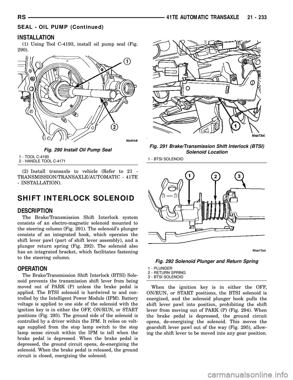
(1) Using Tool C-4193, install oil pump seal (Fig.
290).
(2) Install transaxle to vehicle (Refer to 21 -
TRANSMISSION/TRANSAXLE/AUTOMATIC - 41TE
- INSTALLATION).
SHIFT INTERLOCK SOLENOID
DESCRIPTION
The Brake/Transmission Shift Interlock system
consists of an electro-magnetic solenoid mounted to
the steering column (Fig. 291). The solenoid's plunger
consists of an integrated hook, which operates the
shift lever pawl (part of shift lever assembly), and a
plunger return spring (Fig. 292). The solenoid also
has an integrated bracket, which facilitates fastening
to the steering column.
OPERATION
The Brake/Transmission Shift Interlock (BTSI) Sole-
noid prevents the transmission shift lever from being
moved out of PARK (P) unless the brake pedal is
applied. The BTSI solenoid is hardwired to and con-
trolled by the Intelligent Power Module (IPM). Battery
voltage is applied to one side of the solenoid with the
ignition key is in either the OFF, ON/RUN, or START
positions (Fig. 293). The ground side of the solenoid is
controlled by a driver within the IPM. It relies on volt-
age supplied from the stop lamp switch to the stop
lamp sense circuit within the IPM to tell when the
brake pedal is depressed. When the brake pedal is
depressed, the ground circuit opens, de-energizing the
solenoid. When the brake pedal is released, the ground
circuit is closed, energizing the solenoid.
When the ignition key is in either the OFF,
ON/RUN, or START positions, the BTSI solenoid is
energized, and the solenoid plunger hook pulls the
shift lever pawl into position, prohibiting the shift
lever from moving out of PARK (P) (Fig. 294). When
the brake pedal is depressed, the ground circuit
opens, de-energizing the solenoid. This moves the
gearshift lever pawl out of the way (Fig. 295), allow-
ing the shift lever to be moved into any gear position.
Fig. 290 Install Oil Pump Seal
1 - TOOL C-4193
2 - HANDLE TOOL C-4171
Fig. 291 Brake/Transmission Shift Interlock (BTSI)
Solenoid Location
1 - BTSI SOLENOID
Fig. 292 Solenoid Plunger and Return Spring
1 - PLUNGER
2 - RETURN SPRING
3 - BTSI SOLENOID
RS41TE AUTOMATIC TRANSAXLE21 - 233
SEAL - OIL PUMP (Continued)
Page 1832 of 2585
DIAGNOSIS AND TESTING - BRAKE/
TRANSMISSION SHIFT INTERLOCK SOLENOID
For intended BTSI system operation, refer to the
following chart:
ACTION EXPECTED RESPONSE
1. Turn key to the9OFF9
position.1. Shifter CAN be shifted
out of park with brake
pedal applied.
2. Turn key to the
9ON/RUN9position.2. Shifter CANNOT be
shifted out of park.
3. Turn key to the
9ON/RUN9position and
depress the brake pedal.3. Shifter CAN be shifted
out of park.
4. Leave shifter in any
gear and try to return key
to the9LOCK9or9ACC9
position.4. Key cannot be
returned to the9LOCK9or
9ACC9position.
5. Return shifter to
9PARK9and try to remove
the key.5. Key can be removed
(after returning to9LOCK9
position).
6. With the key removed,
try to shift out of9PARK9.6. Shifter cannot be
shifted out of9PARK9.
NOTE: Any failure to meet these expected
responses requires system repair. Refer to the
appropriate Diagnostic Information.
REMOVAL
(1) Disconnect battery negative cable.
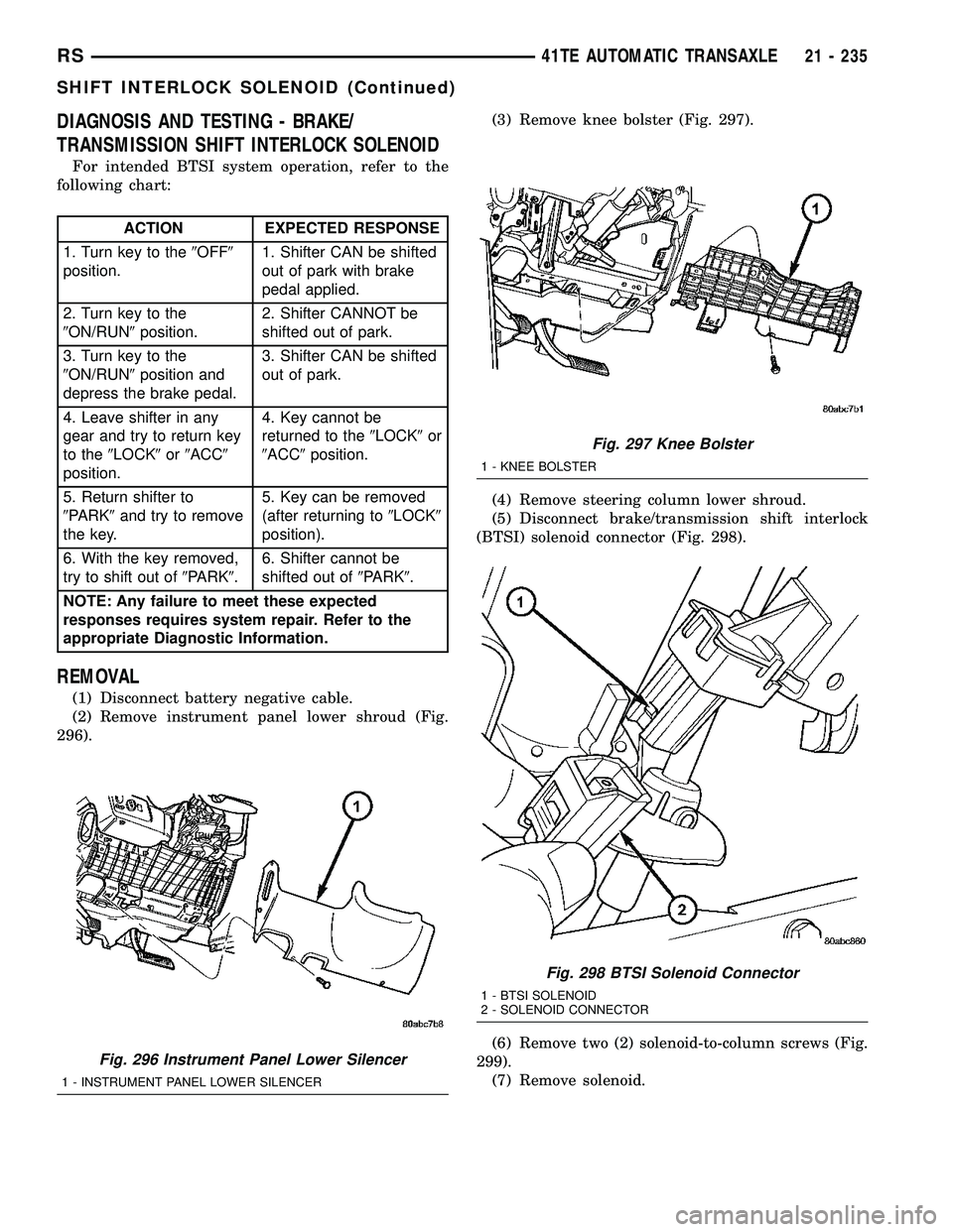
(2) Remove instrument panel lower shroud (Fig.
296).(3) Remove knee bolster (Fig. 297).
(4) Remove steering column lower shroud.
(5) Disconnect brake/transmission shift interlock
(BTSI) solenoid connector (Fig. 298).
(6) Remove two (2) solenoid-to-column screws (Fig.
299).
(7) Remove solenoid.
Fig. 296 Instrument Panel Lower Silencer
1 - INSTRUMENT PANEL LOWER SILENCER
Fig. 297 Knee Bolster
1 - KNEE BOLSTER
Fig. 298 BTSI Solenoid Connector
1 - BTSI SOLENOID
2 - SOLENOID CONNECTOR
RS41TE AUTOMATIC TRANSAXLE21 - 235
SHIFT INTERLOCK SOLENOID (Continued)
Page 1845 of 2585
OPERATION
The relay is supplied fused B+ voltage, energized
by the PCM/TCM, and is used to supply power to the
solenoid pack when the transmission is in normal
operating mode. When the relay is ªoffº, no power is
supplied to the solenoid pack and the transmission is
in ªlimp-inº mode. After a controller reset (ignition
key turned to the ªrunº position or after cranking
engine), the PCM/TCM energizes the relay. Prior to
this, the PCM/TCM verifies that the contacts are
open by checking for no voltage at the switched bat-
tery terminals. After this is verified, the voltage at
the solenoid pack pressure switches is checked. After
the relay is energized, the PCM/TCM monitors the
terminals to verify that the voltage is greater than 3
volts.
TRANSMISSION RANGE
SENSOR
DESCRIPTION
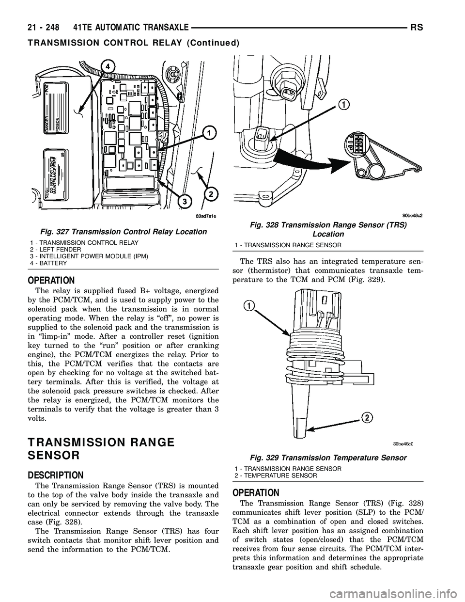
The Transmission Range Sensor (TRS) is mounted
to the top of the valve body inside the transaxle and
can only be serviced by removing the valve body. The
electrical connector extends through the transaxle
case (Fig. 328).
The Transmission Range Sensor (TRS) has four
switch contacts that monitor shift lever position and
send the information to the PCM/TCM.The TRS also has an integrated temperature sen-
sor (thermistor) that communicates transaxle tem-
perature to the TCM and PCM (Fig. 329).
OPERATION
The Transmission Range Sensor (TRS) (Fig. 328)
communicates shift lever position (SLP) to the PCM/
TCM as a combination of open and closed switches.
Each shift lever position has an assigned combination
of switch states (open/closed) that the PCM/TCM
receives from four sense circuits. The PCM/TCM inter-
prets this information and determines the appropriate
transaxle gear position and shift schedule.
Fig. 327 Transmission Control Relay Location
1 - TRANSMISSION CONTROL RELAY
2 - LEFT FENDER
3 - INTELLIGENT POWER MODULE (IPM)
4 - BATTERY
Fig. 328 Transmission Range Sensor (TRS)
Location
1 - TRANSMISSION RANGE SENSOR
Fig. 329 Transmission Temperature Sensor
1 - TRANSMISSION RANGE SENSOR
2 - TEMPERATURE SENSOR
21 - 248 41TE AUTOMATIC TRANSAXLERS
TRANSMISSION CONTROL RELAY (Continued)
Page 1995 of 2585
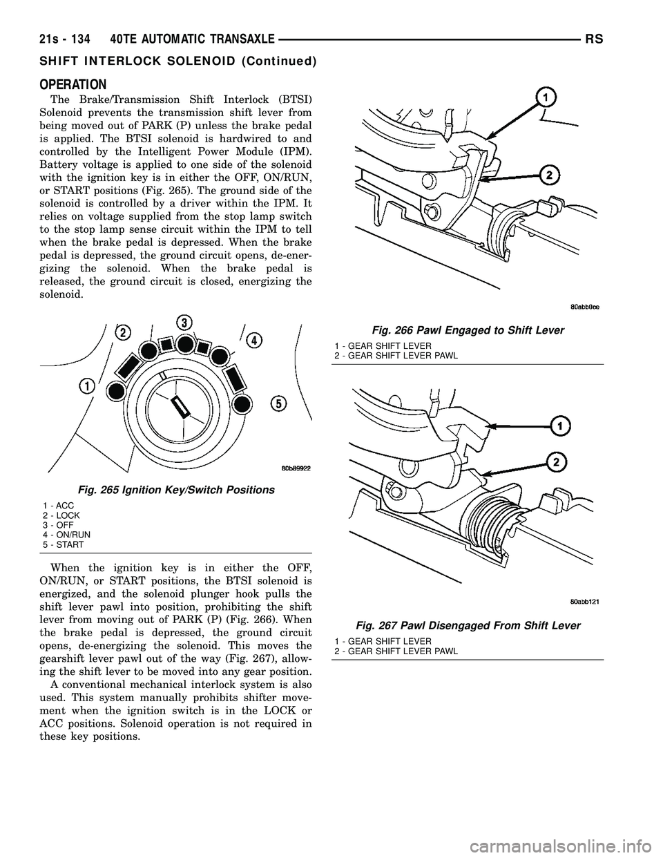
OPERATION
The Brake/Transmission Shift Interlock (BTSI)
Solenoid prevents the transmission shift lever from
being moved out of PARK (P) unless the brake pedal
is applied. The BTSI solenoid is hardwired to and
controlled by the Intelligent Power Module (IPM).
Battery voltage is applied to one side of the solenoid
with the ignition key is in either the OFF, ON/RUN,
or START positions (Fig. 265). The ground side of the
solenoid is controlled by a driver within the IPM. It
relies on voltage supplied from the stop lamp switch
to the stop lamp sense circuit within the IPM to tell
when the brake pedal is depressed. When the brake
pedal is depressed, the ground circuit opens, de-ener-
gizing the solenoid. When the brake pedal is
released, the ground circuit is closed, energizing the
solenoid.
When the ignition key is in either the OFF,
ON/RUN, or START positions, the BTSI solenoid is
energized, and the solenoid plunger hook pulls the
shift lever pawl into position, prohibiting the shift
lever from moving out of PARK (P) (Fig. 266). When
the brake pedal is depressed, the ground circuit
opens, de-energizing the solenoid. This moves the
gearshift lever pawl out of the way (Fig. 267), allow-
ing the shift lever to be moved into any gear position. A conventional mechanical interlock system is also
used. This system manually prohibits shifter move-
ment when the ignition switch is in the LOCK or
ACC positions. Solenoid operation is not required in
these key positions.
Fig. 265 Ignition Key/Switch Positions
1 - ACC
2 - LOCK
3 - OFF
4 - ON/RUN
5-START
Fig. 266 Pawl Engaged to Shift Lever
1 - GEAR SHIFT LEVER
2 - GEAR SHIFT LEVER PAWL
Fig. 267 Pawl Disengaged From Shift Lever
1 - GEAR SHIFT LEVER
2 - GEAR SHIFT LEVER PAWL
21s - 134 40TE AUTOMATIC TRANSAXLERS
SHIFT INTERLOCK SOLENOID (Continued)
Page 1996 of 2585
For intended BTSI system operation, refer to the
following chart:
ACTION EXPECTED RESPONSE
1. Turn key to the 9OFF 9
position. 1. Shifter CAN be shifted
out of park with brake
pedal applied.
2. Turn key to the
9 ON/RUN 9position. 2. Shifter CANNOT be
shifted out of park.
3. Turn key to the
9 ON/RUN 9position and
depress the brake pedal. 3. Shifter CAN be shifted
out of park.
4. Leave shifter in any
gear and try to return key
to the 9LOCK 9or 9ACC 9
position. 4. Key cannot be
returned to the
9LOCK 9or
9 ACC 9position.
5. Return shifter to
9 PARK 9and try to remove
the key. 5. Key can be removed
(after returning to
9LOCK 9
position).
6. With the key removed,
try to shift out of 9PARK 9. 6. Shifter cannot be
shifted out of
9PARK 9.
NOTE: Any failure to meet these expected
responses requires system adjustment or repair.
DIAGNOSIS AND TESTING - BRAKE/
TRANSMISSION SHIFT INTERLOCK SOLENOID
For intended BTSI system operation, refer to the
following chart:
ACTION EXPECTED RESPONSE
1. Turn key to the 9OFF 9
position. 1. Shifter CAN be shifted
out of park with brake
pedal applied.
2. Turn key to the
9 ON/RUN 9position. 2. Shifter CANNOT be
shifted out of park.
3. Turn key to the
9 ON/RUN 9position and
depress the brake pedal. 3. Shifter CAN be shifted
out of park.
4. Leave shifter in any
gear and try to return key
to the 9LOCK 9or 9ACC 9
position. 4. Key cannot be
returned to the
9LOCK 9or
9 ACC 9position.
5. Return shifter to
9 PARK 9and try to remove
the key. 5. Key can be removed
(after returning to
9LOCK 9
position).
6. With the key removed,
try to shift out of 9PARK 9. 6. Shifter cannot be
shifted out of
9PARK 9.
NOTE: Any failure to meet these expected
responses requires system repair. Refer to the
appropriate Diagnostic Information.
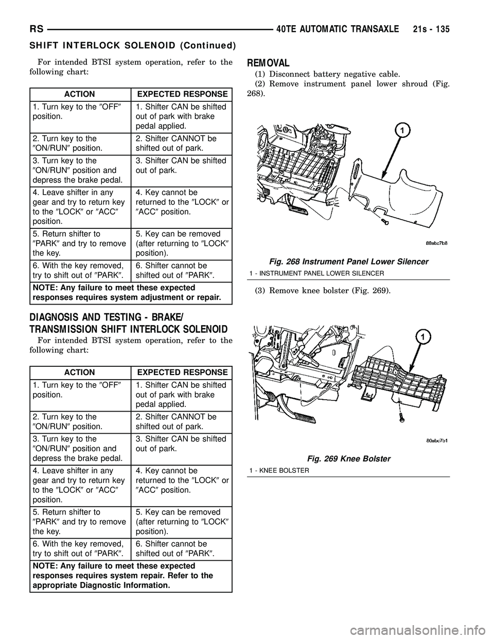
REMOVAL
(1) Disconnect battery negative cable.
(2) Remove instrument panel lower shroud (Fig.
268).
(3) Remove knee bolster (Fig. 269).
Fig. 268 Instrument Panel Lower Silencer
1 - INSTRUMENT PANEL LOWER SILENCER
Fig. 269 Knee Bolster
1 - KNEE BOLSTER
RS 40TE AUTOMATIC TRANSAXLE21s - 135
SHIFT INTERLOCK SOLENOID (Continued)
Page 2011 of 2585
(9)Fill the transmission with the recommended fluid.
(Refer to 21 - TRANSMISSION/TRANSAXLE/AUTO-
MATIC - 41TE/FLUID - STANDARD PROCEDURE)
TRANSMISSION CONTROL RELAY
DESCRIPTION
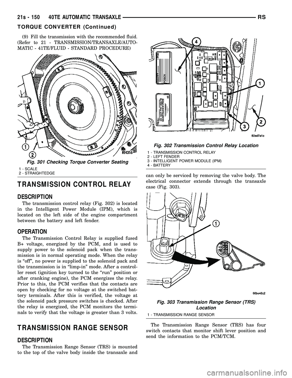
The transmission control relay (Fig. 302) is located
in the Intelligent Power Module (IPM), which is
located on the left side of the engine compartment
between the battery and left fender.
OPERATION
The Transmission Control Relay is supplied fused
B+ voltage, energized by the PCM, and is used to
supply power to the solenoid pack when the trans-
mission is in normal operating mode. When the relay
is ªoffº, no power is supplied to the solenoid pack and
the transmission is in ªlimp-inº mode. After a control-
ler reset (ignition key turned to the ªrunº position or
after cranking engine), the PCM energizes the relay.
Prior to this, the PCM verifies that the contacts are
open by checking for no voltage at the switched bat-
tery terminals. After this is verified, the voltage at
the solenoid pack pressure switches is checked. After
the relay is energized, the PCM monitors the termi-
nals to verify that the voltage is greater than 3 volts.
TRANSMISSION RANGE SENSOR
DESCRIPTION
The Transmission Range Sensor (TRS) is mounted
to the top of the valve body inside the transaxle and can only be serviced by removing the valve body. The
electrical connector extends through the transaxle
case (Fig. 303).
The Transmission Range Sensor (TRS) has four
switch contacts that monitor shift lever position and
send the information to the PCM/TCM.
Fig. 301 Checking Torque Converter Seating
1 - SCALE
2 - STRAIGHTEDGE
Fig. 302 Transmission Control Relay Location
1 - TRANSMISSION CONTROL RELAY
2 - LEFT FENDER
3 - INTELLIGENT POWER MODULE (IPM)
4 - BATTERY
Fig. 303 Transmission Range Sensor (TRS) Location
1 - TRANSMISSION RANGE SENSOR
21s - 150 40TE AUTOMATIC TRANSAXLERS
TORQUE CONVERTER (Continued)
Page 2102 of 2585
TIRES/WHEELS
TABLE OF CONTENTS
page page
TIRE PRESSURE MONITORING............... 1TIRES................................... 5
TIRE PRESSURE MONITORING
TABLE OF CONTENTS
page page
TIRE PRESSURE MONITORING DESCRIPTION ..........................1
OPERATION ............................1
SENSOR - TPM DESCRIPTION ..........................1
OPERATION ............................2
CAUTION ..............................2 DIAGNOSIS AND TESTING - TIRE PRESSURE
SENSOR .............................2
STANDARD PROCEDURE - TIRE PRESSURE SENSOR RETRAIN .....................2
REMOVAL .............................2
INSTALLATION ..........................3
TIRE PRESSURE MONITORING
DESCRIPTION
Some versions of this vehicle are equipped with a
Tire Pressure Monitoring (TPM) system. It monitors
air pressure in the four road tires. Pressure in the
spare tire is not monitored. There is a sensor (transmitter) in each of the vehi-
cle's four road wheels that is built in to the valve
stem. The system alerts the driver when tire pres-
sure falls outside predetermined thresholds (pressure
too low or too high). A message is then displayed on
the Compass Mini Trip Computer (CMTC). For further information, refer to the Owners Man-
ual or the appropriate diagnostic information.
OPERATION
The Tire Pressure Monitoring (TPM) system uses
radio and sensor technology to monitor tire air pres-
sure levels. Sensors, mounted to each road wheel as
part of the valve stem, transmit an RF frequency
indicating their individual pressure to a receiver
located in the Sentry Key Remote Entry Module
(SKREEM). These transmissions occur approximately
once every minute at speeds over 13 mph (20 km/h).
The Tire Pressure Monitoring system remains active
even if no tire pressure related message is displayed.
SENSOR - TPM
DESCRIPTION
On vehicles equipped with Tire Pressure Monitor-
ing, one tire pressure sensor is mounted to each
wheel (Fig. 2). Each sensor has an internal battery
that lasts up to 10 years. The battery is not service-
able. At the time of battery failure, the sensor must
be replaced. The serviceable components of the tire
pressure sensor are: ² Sensor-To-Wheel Grommet
² Valve Stem Cap
² Valve Stem Core
Valve stem caps and cores are specifically designed
for the tire pressure monitoring sensors. Although
similar to standard valve stem caps and cores, they
are different.
CAUTION: Do not use a standard valve stem cap or
core in a tire pressure sensor. Always use the orig-
inal equipment style sensor cap and core.
CAUTION: Do not reuse the Sensor-To Wheel Grom-
met. Always use a new grommet when installing a
pressure sensor and properly torque the sensor
nut.
RS TIRES/WHEELS22s-1