2004 CHRYSLER VOYAGER instrument panel
[x] Cancel search: instrument panelPage 449 of 2585

STARTING
TABLE OF CONTENTS
page page
STARTING
DESCRIPTION.........................28
OPERATION...........................28
DIAGNOSIS AND TESTING
DIAGNOSIS AND TESTING - STARTING
SYSTEM TEST.......................28
DIAGNOSIS AND TESTING - CONTROL
CIRCUIT TEST........................30
DIAGNOSIS AND TESTING - FEED CIRCUIT
RESISTANCE TEST....................32
DIAGNOSIS AND TESTING - FEED CIRCUIT
TEST...............................33SPECIFICATIONS
Torques.............................33
STARTER ...........................34
STARTER MOTOR
REMOVAL
REMOVAL - 2.4L......................34
REMOVAL - 3.3/3.8L...................35
INSTALLATION
INSTALLATION - 2.4L..................35
INSTALLATION - 3.3/3.8L................36
STARTING
DESCRIPTION
The starting system consists of:
²Starter relay
²Starter motor (including an integral starter sole-
noid)
Other components to be considered as part of start-
ing system are:
²Battery
²Battery cables
²Ignition switch and key lock cylinder
²Clutch pedal position switch (manual transmis-
sion)
²Park/neutral position switch (automatic trans-
mission)
²Wire harnesses and connections.
The Battery, Starting, and Charging systems oper-
ate in conjunction with one another, and must be
tested as a complete system. For correct operation of
starting/charging systems, all components used in
these 3 systems must perform within specifications.
When attempting to diagnose any of these systems, it
is important that you keep their interdependency in
mind.
The diagnostic procedures used in each of these
groups include the most basic conventional diagnostic
methods, to the more sophisticated On-Board Diag-
nostics (OBD) built into the Powertrain Control Mod-
ule (PCM). Use of an induction-type milliampere
ammeter, volt/ohmmeter, battery charger, carbon pile
rheostat (load tester), and 12-volt test lamp may be
required.
OPERATION
These components form two separate circuits. A
high amperage circuit that feeds the starter motor up
to 300+ amps, and a control circuit that operates on
less than 20 amps.
The PCM controls a double start over-ride safety
that does not allow the starter to be engaged if the
engine is already running.
DIAGNOSIS AND TESTING
DIAGNOSIS AND TESTING - STARTING
SYSTEM TEST
For circuit descriptions and diagrams, refer to the
Wiring Diagrams.
WARNING: ON VEHICLES EQUIPPED WITH AIR-
BAGS, REFER TO THE PASSIVE RESTRAINT SYS-
TEMS BEFORE ATTEMPTING STEERING WHEEL,
STEERING COLUMN, OR INSTRUMENT PANEL
COMPONENT DIAGNOSIS OR SERVICE. FAILURE
TO TAKE THE PROPER PRECAUTIONS COULD
RESULT IN ACCIDENTAL AIRBAG DEPLOYMENT
AND POSSIBLE PERSONAL INJURY.
INSPECTION
Before removing any unit from the starting system
for repair or diagnosis, perform the following inspec-
tions:
²Battery- Visually inspect the battery for indi-
cations of physical damage and loose or corroded
cable connections. Determine the state-of-charge and
cranking capacity of the battery. Charge or replace
8F - 28 STARTINGRS
Page 478 of 2585

ULES/POWERTRAIN CONTROL MODULE -
DESCRIPTION) section for more DTC information.The Charging system ªBatteryº light indicates
problems with the charging system (voltage too high/
low, generator failure, etc.). If an extreme condition is
indicated, the lamp will be illuminated. The signal to
activate the lamp is sent via the PCI bus circuits.
The lamp is located on the instrument panel. Refer
to the Instrument Cluster section for additional infor-
mation. The PCM uses the ambient air temperature sensor
to control the charge system voltage. This tempera-
ture, along with data from monitored line voltage, is
used by the PCM to vary the battery charging rate.
The system voltage is higher at cold temperatures
and is gradually reduced as the calculated battery
temperature increases. The ambient temperature sensor is used to control
the battery voltage based upon ambient temperature
(approximation of battery temperature). The PCM
maintains the optimal output of the generator by
monitoring battery voltage and controlling it to a
range of 13.5 - 14.7 volts based on battery tempera-
ture.
DIAGNOSIS AND TESTING - ON-BOARD
DIAGNOSTIC SYSTEM
The Powertrain Control Module (PCM) monitors
critical input and output circuits of the charging sys-
tem, making sure they are operational. A Diagnostic
Trouble Code (DTC) is assigned to each input and
output circuit monitored by the OBD system. Some
circuits are checked continuously and some are
checked only under certain conditions. If the OBD system senses that a monitored circuit
is bad, it will put a DTC into electronic memory. The
DTC will stay in electronic memory as long as the
circuit continues to be bad. The PCM is programmed
to clear the memory after 40 good trip if the problem
does not occur again.
DIAGNOSTIC TROUBLE CODES
A DTC description can be read using the DRBIII t
scan tool. Refer to the appropriate Powertrain Diag-
nostic Procedures manual for information. A DTC does not identify which component in a cir-
cuit is bad. Thus, a DTC should be treated as a
symptom, not as the cause for the problem. In some
cases, because of the design of the diagnostic test
procedure, a DTC can be the reason for another DTC
to be set. Therefore, it is important that the test pro-
cedures be followed in sequence, to understand what
caused a DTC to be set. ERASING DIAGNOSTIC TROUBLE CODES
The DRBIII tScan Tool must be used to erase a
DTC. The following procedures may be used to diagnose
the charging system if: ² the check gauges lamp or battery lamp is illumi-
nated with the engine running ² the voltmeter (if equipped) does not register
properly ² an undercharged or overcharged battery condi-
tion occurs. Remember that an undercharged battery is often
caused by: ² accessories being left on with the engine not
running ² a faulty or improperly adjusted switch that
allows a lamp to stay on. Refer to Ignition-Off Draw
Test (Refer t o 8 - ELECTRICAL/BATTERY SYSTEM/
BATTERY - STANDARD PROCEDURE) ² loose generator belt.
INSPECTION The Powertrain Control Module (PCM) monitors
critical input and output circuits of the charging sys-
tem, making sure they are operational. A Diagnostic
Trouble Code (DTC) is assigned to each input and
output circuit monitored by the On-Board Diagnostic
(OBD) system. Some charging system circuits are
checked continuously, and some are checked only
under certain conditions. Refer to Diagnostic Trouble Codes in; Powertrain
Control Module; Electronic Control Modules for more
DTC information. This will include a complete list of
DTC's including DTC's for the charging system. To perform a complete test of the charging system,
refer to the appropriate Powertrain Diagnostic Proce-
dures service manual and the DRBIII tscan tool.
Perform the following inspections before attaching
the scan tool. (1) Inspect the battery condition. Refer to the Bat-
tery section (Refer t o 8 - ELECTRICAL/BATTERY
SYSTEM - DIAGNOSIS AND TESTING) for proce-
dures. (2) Inspect condition of battery cable terminals,
battery posts, connections at engine block, starter
solenoid and relay. They should be clean and tight.
Repair as required. (3) Inspect all fuses in both the fuseblock and
Power Distribution Center (PDC) or IPM (if
equipped) for tightness in receptacles. They should be
properly installed and tight. Repair or replace as
required. (4) Inspect generator mounting bolts for tightness.
Replace or tighten bolts if required. Refer to the Gen-
erator Removal/Installation section of this group for
RS CHARGING8Fs-21
CHARGING (Continued)
Page 487 of 2585

STARTING
TABLE OF CONTENTS
page page
STARTING DESCRIPTION .........................30
OPERATION ...........................30
DIAGNOSIS AND TESTING DIAGNOSIS AND TESTING - STARTINGSYSTEM TEST .......................30
DIAGNOSIS AND TESTING - CONTROL CIRCUIT TEST ........................32
DIAGNOSIS AND TESTING - FEED CIRCUIT RESISTANCE TEST ....................34
DIAGNOSIS AND TESTING - FEED CIRCUIT TEST ...............................35 SPECIFICATIONS
Torques .............................35
STARTER ...........................36
STARTER MOTOR REMOVAL REMOVAL - 2.4L ......................36
REMOVAL - 3.3/3.8L ...................36
REMOVAL - 2.5L ......................36
INSTALLATION INSTALLATION - 2.4L ..................37
INSTALLATION - 3.3/3.8L ................37
INSTALLATION - 2.5L ..................38
STARTING
DESCRIPTION
The starting system consists of:
²Starter relay
² Starter motor (including an integral starter sole-
noid) Other components to be considered as part of start-
ing system are: ² Battery
² Battery cables
² Ignition switch and key lock cylinder
² Clutch pedal position switch (manual transmis-
sion) ² Park/neutral position switch (automatic trans-
mission) ² Wire harnesses and connections.
The Battery, Starting, and Charging systems oper-
ate in conjunction with one another, and must be
tested as a complete system. For correct operation of
starting/charging systems, all components used in
these 3 systems must perform within specifications.
When attempting to diagnose any of these systems, it
is important that you keep their interdependency in
mind. The diagnostic procedures used in each of these
groups include the most basic conventional diagnostic
methods, to the more sophisticated On-Board Diag-
nostics (OBD) built into the Powertrain Control Mod-
ule (PCM). Use of an induction-type milliampere
ammeter, volt/ohmmeter, battery charger, carbon pile
rheostat (load tester), and 12-volt test lamp may be
required.
OPERATION
These components form two separate circuits. A
high amperage circuit that feeds the starter motor up
to 300+ amps, and a control circuit that operates on
less than 20 amps. The PCM controls a double start over-ride safety
that does not allow the starter to be engaged if the
engine is already running.
DIAGNOSIS AND TESTING
DIAGNOSIS AND TESTING - STARTING
SYSTEM TEST
For circuit descriptions and diagrams, refer to the
Wiring Diagrams.
WARNING: ON VEHICLES EQUIPPED WITH AIR-
BAGS, REFER TO THE PASSIVE RESTRAINT SYS-
TEMS BEFORE ATTEMPTING STEERING WHEEL,
STEERING COLUMN, OR INSTRUMENT PANEL
COMPONENT DIAGNOSIS OR SERVICE. FAILURE
TO TAKE THE PROPER PRECAUTIONS COULD
RESULT IN ACCIDENTAL AIRBAG DEPLOYMENT
AND POSSIBLE PERSONAL INJURY.
INSPECTION
Before removing any unit from the starting system
for repair or diagnosis, perform the following inspec-
tions: ² Battery - Visually inspect the battery for indi-
cations of physical damage and loose or corroded
cable connections. Determine the state-of-charge and
cranking capacity of the battery. Charge or replace
8Fs - 30 STARTINGRS
Page 496 of 2585

HEATED SYSTEMS
TABLE OF CONTENTS
page page
HEATED GLASS........................... 1
HEATED MIRRORS......................... 6HEATED SEAT SYSTEM..................... 7
HEATED GLASS
TABLE OF CONTENTS
page page
HEATED GLASS
DESCRIPTION..........................1
OPERATION............................2
DIAGNOSIS AND TESTING - REAR WINDOW
DEFOGGER SYSTEM...................2
REAR WINDOW DEFOGGER RELAY
DESCRIPTION..........................3
OPERATION............................3REMOVAL.............................3
INSTALLATION..........................3
REAR WINDOW DEFOGGER SWITCH
DESCRIPTION..........................4
OPERATION............................4
REAR WINDOW DEFOGGER GRID
STANDARD PROCEDURE - GRID LINE AND
TERMINAL REPAIR.....................4
HEATED GLASS
DESCRIPTION
CAUTION: Grid lines can be damaged or scraped
off with sharp instruments. Care should be taken in
cleaning glass or removing foreign materials,
decals or stickers. Normal glass cleaning solvents
or hot water used with rags or toweling is recom-
mended.
The rear window defogger system consists of two
vertical bus bars linked by a series of grid lines fired
onto the inside surface of the rear window (Fig. 1).
The rear window defogger system is turned ON or
OFF by a control switch located on the A/C-heater
control at the center of the instrument panel and by
a rear window defogger relay timing circuit integral
to the integrated power module (IPM) (Refer to 8 -
ELECTRICAL/HEATED GLASS/REAR WINDOW
DEFOGGER SWITCH - DESCRIPTION).
Circuit protection is provided by a 40 amp fuse
located in the IPM.
Fig. 1 Rear Window Defogger - Typical
1 - REAR DEFOGGER GRID
2 - REAR WINDOW
RSHEATED SYSTEMS8G-1
Page 497 of 2585
OPERATION
When the rear window defogger button is
depressed to the On position, current is directed to
the rear defogger grid lines and the heated power
mirrors (if equipped). The heated grid lines heat the
glass to help clear the rear window and side mirror
surfaces of fog or frost.
The defogger system is controlled by a momentary
switch located in the A/C-heater control on the
instrument panel. A yellow indicator in the switch
will illuminate to indicate when the defogger system
is turned on. The integrated power module (IPM)
contains the defogger system control circuitry.
NOTE:
The rear window defogger turns off automat-
ically after approximately 10 minutes of initial opera-
tion. Each following activation cycle of the defogger
system will last approximately five minutes.
The defogger system will be automatically turned
off after a programmed time interval of about ten
minutes. After the initial time interval has expired, if
the defogger switch is turned on again during the
same ignition cycle, the defogger system will auto-
matically turn off after about five minutes.
The defogger system will automatically shut off if
the ignition switch is turned to the Off position, or it
can be turned off manually by depressing the defog-
ger switch a second time.
DIAGNOSIS AND TESTING - REAR WINDOW
DEFOGGER SYSTEM
The electrically heated rear window defogger oper-
ation can be checked on the vehicle in the following
manner:
(1) Turn the ignition switch to the On position.
(2) Make sure that the defogger switch is Off.
(3) Using a ammeter on the battery, turn the rear
defogger control switch to the On position, a distinct
increase in amperage draw should be noted.
(4) The rear window defogger operation can be
checked by feeling the glass. A distinct difference in
temperature between the grid lines and adjacent
clear glass should be detected in three to four min-
utes of operation.
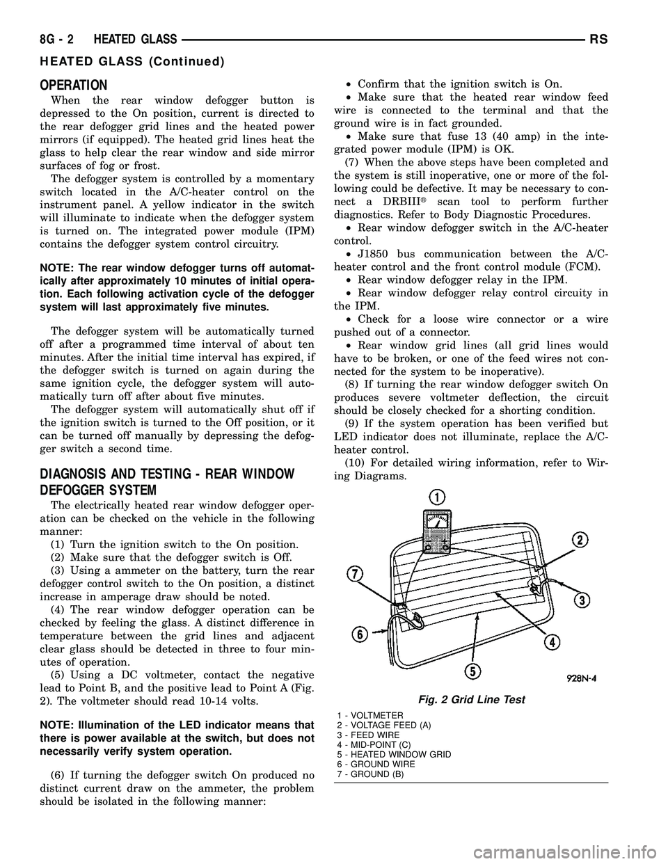
(5) Using a DC voltmeter, contact the negative
lead to Point B, and the positive lead to Point A (Fig.
2). The voltmeter should read 10-14 volts.
NOTE: Illumination of the LED indicator means that
there is power available at the switch, but does not
necessarily verify system operation.
(6) If turning the defogger switch On produced no
distinct current draw on the ammeter, the problem
should be isolated in the following manner:²Confirm that the ignition switch is On.
²Make sure that the heated rear window feed
wire is connected to the terminal and that the
ground wire is in fact grounded.
²Make sure that fuse 13 (40 amp) in the inte-
grated power module (IPM) is OK.
(7) When the above steps have been completed and
the system is still inoperative, one or more of the fol-
lowing could be defective. It may be necessary to con-
nect a DRBIIItscan tool to perform further
diagnostics. Refer to Body Diagnostic Procedures.
²Rear window defogger switch in the A/C-heater
control.
²J1850 bus communication between the A/C-
heater control and the front control module (FCM).
²Rear window defogger relay in the IPM.
²Rear window defogger relay control circuity in
the IPM.
²Check for a loose wire connector or a wire
pushed out of a connector.
²Rear window grid lines (all grid lines would
have to be broken, or one of the feed wires not con-
nected for the system to be inoperative).
(8) If turning the rear window defogger switch On
produces severe voltmeter deflection, the circuit
should be closely checked for a shorting condition.
(9) If the system operation has been verified but
LED indicator does not illuminate, replace the A/C-
heater control.
(10) For detailed wiring information, refer to Wir-
ing Diagrams.
Fig. 2 Grid Line Test
1 - VOLTMETER
2 - VOLTAGE FEED (A)
3 - FEED WIRE
4 - MID-POINT (C)
5 - HEATED WINDOW GRID
6 - GROUND WIRE
7 - GROUND (B)
8G - 2 HEATED GLASSRS
HEATED GLASS (Continued)
Page 499 of 2585

(2) Position the rear window defogger relay into
the proper receptacle in the IPM.
(3) Align the rear window defogger relay terminals
with the terminal cavities in the IPM receptacle.
(4) Push down firmly on the rear window defogger
relay until the terminals are fully seated in the ter-
minal cavities in the IPM receptacle.
(5) Install the cover onto the IPM.
(6) Reconnect the battery negative cable.
REAR WINDOW DEFOGGER
SWITCH
DESCRIPTION
The rear window defogger switch is integrated into
the A/C-heater control mounted in the center of the
instrument panel (Fig. 5). The rear window defogger
switch and the rear window defogger LED indicator
cannot be repaired and, if faulty or damaged, the
A/C-heater control must be replaced.
OPERATION
An LED indicator will illuminate when the rear
window defogger switch is activated. The switch
energizes the A/C-heater control module which then
requests the front control module (FCM) to activate
the rear window defogger relay via the J1850 com-
munication bus. The rear window defogger relay con-
trols the current to flow to the grids of the rear
window defogger and the heated power side view
mirrors. The defogger relay will be on for approxi-
mately 10 minutes or until the control switch or igni-
tion is turned off.
REAR WINDOW DEFOGGER
GRID
STANDARD PROCEDURE - GRID LINE AND
TERMINAL REPAIR
REAR WINDOW DEFOGGER GRID LINE REPAIR
WARNING: THE REPAIR KIT CONTAINS EPOXY
RESIN AND AMINE TYPE HARDENER WHICH MAY
CAUSE SKIN OR EYE IRRITATION AND CAN BE
HARMFUL IF SWALLOWED. USE WITH ADEQUATE
VENTILATION. DO NOT USE NEAR FIRE OR OPEN
FLAME THE CONTENTS CONTAIN FLAMMABLE
SOLVENTS. KEEP OUT OF REACH OF CHILDREN.
²DO NOT TAKE INTERNALLY, IF SWALLOWED
INDUCE VOMITING AND CALL A PHYSICIAN IMME-
DIATELY.
²IF SKIN CONTACT OCCURS, WASH AFFECTED
AREAS WITH SOAP AND WATER.
²IF EYE CONTACT OCCURS, FLUSH WITH
PLENTY OF WATER.
The repair of the grid lines is possible using the
MopartGrid Line Repair Package or an equivalent.
(1) Mask the repair area so the conductive epoxy
can be extended onto the grid line(s) or the bus bar
(Fig. 6).
(2) Follow the instructions in the repair kit for
preparing the damaged area.
(3) Remove the package separator clamp and mix
the conductive epoxy thoroughly. Fold in half and cut
the center corner to dispense the epoxy.
(4) Apply the conductive epoxy through the slit in
the masking tape. Overlap both ends of the break(s)
by 19 mm (3/4 inch).
(5) Carefully remove the masking tape from the
grid line(s).
CAUTION: To prevent the glass from fracturing, do
not allow the glass surface to exceed 204É C (400É
F).
(6) Allow the epoxy to cure 24 hours at room tem-
perature or use a heat gun with a 260É to 371É C
(500É to 700É F) range for 15 minutes. Hold the heat
gun approximately 254 mm (10 inches) from the
repaired area.
(7) After the conductive epoxy is properly cured,
verify operation of the rear window defogger.
Fig. 5 A/C-Heater Control - Typical
1 - TRIM BEZEL
2 - INFRARED TEMPERATURE SENSOR
3 - A/C REQUEST SWITCH
4 - REAR WINDOW DEFOGGER/HEATED MIRRORS SWITCH
5 - FRONT WINDOW DEFROSTER MODE SELECTOR
8G - 4 HEATED GLASSRS
REAR WINDOW DEFOGGER RELAY (Continued)
Page 502 of 2585

HEATED SEAT SYSTEM
TABLE OF CONTENTS
page page
HEATED SEAT SYSTEM
DESCRIPTION..........................7
OPERATION............................8
DIAGNOSIS AND TESTING - HEATED SEAT
SYSTEM.............................8
DRIVER HEATED SEAT SWITCH
DESCRIPTION..........................8
OPERATION............................8
DIAGNOSIS AND TESTING - DRIVER HEATED
SEAT SWITCH.........................9
REMOVAL.............................10
INSTALLATION.........................10
HEATED SEAT ELEMENTS
DESCRIPTION.........................10
OPERATION...........................10
DIAGNOSIS AND TESTING - HEATED SEAT
ELEMENTS..........................10REMOVAL.............................11
INSTALLATION.........................11
HEATED SEAT SENSOR
DESCRIPTION.........................12
OPERATION...........................12
DIAGNOSIS AND TESTING - HEATED SEAT
SENSOR............................12
PASSENGER HEATED SEAT SWITCH
DESCRIPTION.........................12
OPERATION...........................12
DIAGNOSIS AND TESTING - PASSENGER
HEATED SEAT SWITCH.................13
REMOVAL.............................14
INSTALLATION.........................14
HEATED SEAT SYSTEM
DESCRIPTION
Vehicles with the heated seat option can be visu-
ally identified by the two separate heated seatswitches located in the instrument panel center
stack, just above the radio (Fig. 1). The heated seat
system allows the front seat driver and passenger to
select from two different levels of supplemental elec-
trical seat heating (HI/LO), or no seat heating to suit
their individual comfort requirements. The heated
seat system for this vehicle includes the following
major components, which are described in further
detail later in this section:
²Heated Seat Elements- Four heated seat ele-
ments are used per vehicle, two for each front seat.
One heated seat element is integral to each front
seat trim cover, one in the seat back and one in the
seat bottom (cushion). Service replacement heating
elements are available, refer to heated seat elements
later in this section for additional information.
²Heated Seat Modules- Two heated seat mod-
ules are used per vehicle. One module is mounted to
each of the seat cushion pans, located under the for-
ward edge of each front seat. Refer to heated seat
module in the electronic control modules section of
the service manual for additional information.
²Heated Seat Sensors- Two heated seat sen-
sors are used per vehicle, one for each front seat. The
heated seat sensors are integral to each of the heated
seat bottoms (cushions).
²Heated Seat Switch- Two heated seat
switches are used per vehicle, one for the driver and
one for the passenger side front seats. The switches
are mounted in the instrument panel center stack.
Fig. 1 HEATED SEAT SWITCH LOCATIONS
1 - HEATED SEAT SWITCHES
RSHEATED SEAT SYSTEM8G-7
Page 503 of 2585

Refer to the description of the heated seat switch
later in this section for additional information.
Hard wired circuitry connects the heated seat sys-
tem components to each other through the electrical
system of the vehicle. These hard wired circuits are
integral to several wire harnesses, which are routed
throughout the vehicle and retained by many differ-
ent methods. These circuits may be connected to each
other, to the vehicle electrical system and to the
heated seat system components through the use of a
combination of soldered splices and splice block con-
nectors. Refer to Wiring for complete system wiring
schematics. The wiring information also includes the
proper wire and connector repair procedures, further
details on wire harness routing and retention, as well
as pin-out and location views for the various wire
harness connectors, splices and grounds.
OPERATION
The heated seat system components operate on
battery current received through a fuse in the Inte-
grated Power Module (IPM) on a fused ignition
switch output (run) circuit from the Body Control
Module. The system will only operate when the igni-
tion switch is in the On position. The heated seat
system will be turned Off automatically whenever
the ignition switch is turned to any position except
On. Also, the heated seat system will not operate
when the surface temperature of the seat cushion
cover at either heated seat sensor is above the
designed temperature set points of the system. See
the owner's manual in the vehicle glove box for more
information on the features, use and operation of the
heated seat system.
DIAGNOSIS AND TESTING - HEATED SEAT
SYSTEM
The most reliable, efficient, and accurate means to
diagnose the heated seat system requires the use of a
DRBIIItscan tool and the proper Diagnostic Proce-
dures manual. The DRBIIItscan tool can provide
confirmation that the PCI data bus is functional, that
all of the electronic modules are sending and receiv-
ing the proper messages on the PCI data bus, and
that the heated seat modules are receiving the
proper hard wired inputs from and relaying the
proper hard wired outputs to the Body Control Mod-
ule in order to perform its functions. Refer toWiring
Diagramsfor complete wiring schematics. The wir-
ing information also includes the proper wire and
connector repair procedures, further details on wire
harness routing and retention, as well as pin-out and
location views for the various wire harness connec-
tors, splices and grounds.
DRIVER HEATED SEAT
SWITCH
DESCRIPTION
The heated seat switches are mounted in the
instrument panel center bezel (Fig. 2). The two three-
position rocker-type switches, one switch for each
front seat, are incorporated into one large switch
assembly that also includes the hazard, rear window
wiper and washer switches. The heated seat switches
each provide a resistor multiplexed signal to its
respective Heated Seat Module (HSM) through sepa-
rate hard wired circuits. Each switch has an Off,
Low, and High position so that both the driver and
the front seat passenger can select a preferred seat
heating mode. Each switch has two Light-Emitting
Diodes (LED) which light to indicate that the heater
for the seat is turned on.
The heated seat switches and their LEDs cannot
be repaired. If either switch or LED is faulty or dam-
aged, the entire switch assembly must be replaced.
OPERATION
There are three positions that can be selected with
each of the heated seat switches: Off, Low, or High.
When the left side of the switch rocker is fully
depressed, the Low position is selected and the low
position LED indicator illuminates. When the right
side of the switch rocker is fully depressed, the High
position is selected and the high position LED indi-
Fig. 2 HEATED SEAT SWITCH LOCATION
1 - HEATED SEAT SWITCHES
8G - 8 HEATED SEAT SYSTEMRS
HEATED SEAT SYSTEM (Continued)