2004 CHRYSLER VOYAGER fuel pump
[x] Cancel search: fuel pumpPage 1839 of 2585
INSTALLATION
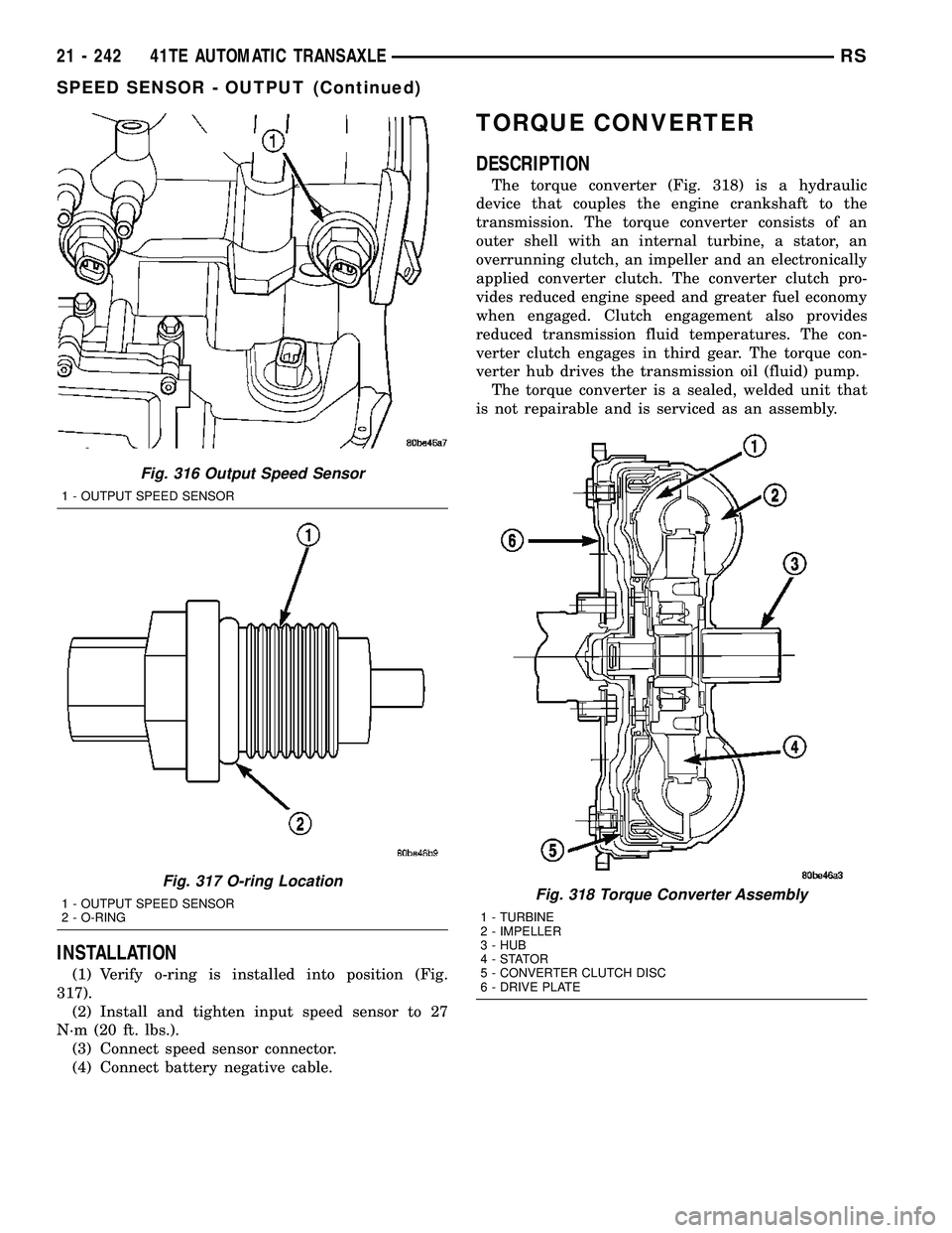
(1) Verify o-ring is installed into position (Fig.
317).
(2) Install and tighten input speed sensor to 27
N´m (20 ft. lbs.).
(3) Connect speed sensor connector.
(4) Connect battery negative cable.
TORQUE CONVERTER
DESCRIPTION
The torque converter (Fig. 318) is a hydraulic
device that couples the engine crankshaft to the
transmission. The torque converter consists of an
outer shell with an internal turbine, a stator, an
overrunning clutch, an impeller and an electronically
applied converter clutch. The converter clutch pro-
vides reduced engine speed and greater fuel economy
when engaged. Clutch engagement also provides
reduced transmission fluid temperatures. The con-
verter clutch engages in third gear. The torque con-
verter hub drives the transmission oil (fluid) pump.
The torque converter is a sealed, welded unit that
is not repairable and is serviced as an assembly.
Fig. 316 Output Speed Sensor
1 - OUTPUT SPEED SENSOR
Fig. 317 O-ring Location
1 - OUTPUT SPEED SENSOR
2 - O-RINGFig. 318 Torque Converter Assembly
1 - TURBINE
2 - IMPELLER
3 - HUB
4-STATOR
5 - CONVERTER CLUTCH DISC
6 - DRIVE PLATE
21 - 242 41TE AUTOMATIC TRANSAXLERS
SPEED SENSOR - OUTPUT (Continued)
Page 2005 of 2585
TORQUE CONVERTER
DESCRIPTION
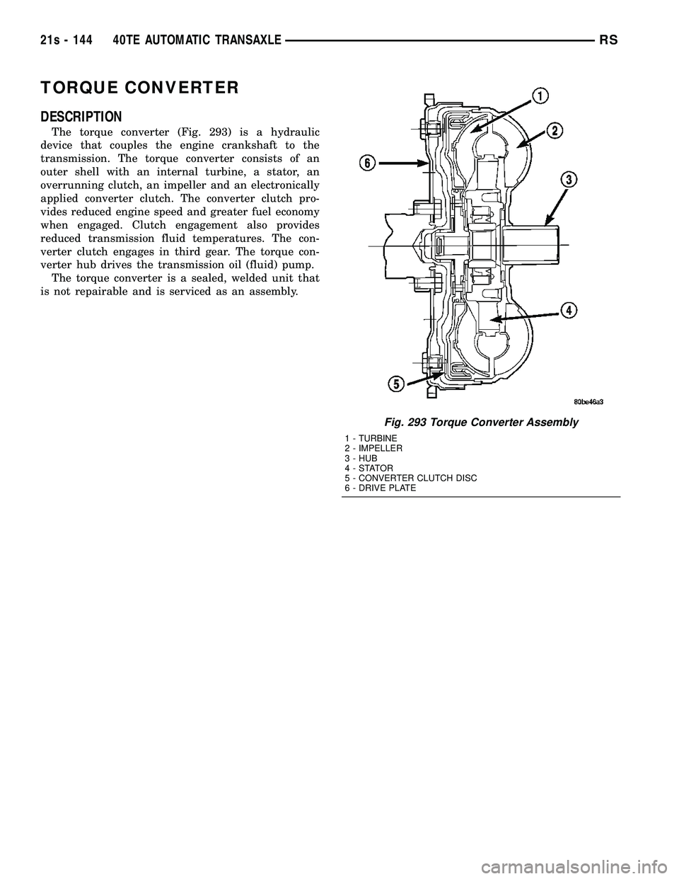
The torque converter (Fig. 293) is a hydraulic
device that couples the engine crankshaft to the
transmission. The torque converter consists of an
outer shell with an internal turbine, a stator, an
overrunning clutch, an impeller and an electronically
applied converter clutch. The converter clutch pro-
vides reduced engine speed and greater fuel economy
when engaged. Clutch engagement also provides
reduced transmission fluid temperatures. The con-
verter clutch engages in third gear. The torque con-
verter hub drives the transmission oil (fluid) pump. The torque converter is a sealed, welded unit that
is not repairable and is serviced as an assembly.
Fig. 293 Torque Converter Assembly
1 - TURBINE
2 - IMPELLER
3 - HUB
4-STATOR
5 - CONVERTER CLUTCH DISC
6 - DRIVE PLATE
21s - 144 40TE AUTOMATIC TRANSAXLERS
Page 2507 of 2585
CABIN HEATER
TABLE OF CONTENTS
page page
CABIN HEATER
DESCRIPTION........................112
OPERATION
OPERATION - MANUAL TEMPERATURE
CONTROL SYSTEM...................112
OPERATION - AUTOMATIC TEMPERATURE
CONTROL SYSTEM...................112
DIAGNOSIS AND TESTING - DIESEL
SUPPLEMENTAL CABIN HEATER........113
AIR INTAKE PIPE
REMOVAL............................113
INSTALLATION........................114
EXHAUST TUBE
REMOVAL............................114
INSTALLATION........................115FUEL DOSING PUMP
DESCRIPTION........................115
OPERATION..........................115
REMOVAL............................115
INSTALLATION........................116
FUEL LINE
STANDARD PROCEDURE - CLEANING.....117
REMOVAL............................117
INSTALLATION........................118
HEATER UNIT
REMOVAL............................118
INSTALLATION........................119
SUPPLEMENTAL DIESEL HEATER WIRING
REMOVAL............................119
INSTALLATION........................119
CABIN HEATER
DESCRIPTION
Vehicles equipped with the diesel engine are also
equipped with a supplemental cabin heater. This
cabin heater is mounted under the vehicle and oper-
ates similar to an oil fired furnace. The heater burns
small amounts of fuel to provide additional heat to
the coolant. Coolant is routed from the engine, to the
supplemental cabin heater and then to the front
heater core. This provides additional heat to the pas-
senger compartment. The supplemental cabin heater
system is interfaced to the vehicles on-board com-
puter systems and DRBIIItdiagnostics.
The supplemental cabin heater has an electronic
control module that monitors the heat output of the
heater. The cabin heater operates at full load (5 kW),
half load or idle mode (no additional heat) depending
on engine coolant temperature.
OPERATION
OPERATION - MANUAL TEMPERATURE
CONTROL SYSTEM
The supplemental cabin heater is activated via the
temperature slide control or knob on the A/C-heater
control when equipped with the manual temperature
control (MTC) system. If the slide control or knob is
moved to or above the upper set point the cabin
heater is activated. The cabin heater can operate in a
full or partial load range as well as an idle mode alldependent on the engine coolant temperature. The
cabin heater will also turn off if the A/C-heater tem-
perature control is lowered to less than the lower set
point. The cabin heater can take up to three minutes
to completely shut down when either the heater tem-
perature is set below the lower set point or the vehi-
cle ignition is shut down.
NOTE: Do not apply a strong vacuum source such
as a garage ventilation system directly on the sup-
plemental cabin heater exhaust line. Too strong of a
vacuum can prevent the supplemental cabin heater
from starting. If required, place the vacuum source
at least 75 mm (3 in.) away from the exhaust line.
The supplemental cabin heater only operates when
the engine is running, the mileage exceeds 8 kilome-
ter (5 mph) and the fuel tank volume exceeds 1/8 of a
tank. The supplemental heater control module moni-
tors blower speed and combustion during its start-up.
The cabin heater should operate if the coolant tem-
perature is below 40É C (104É F).
OPERATION - AUTOMATIC TEMPERATURE
CONTROL SYSTEM
The automatic temperature control (ATC) system
will activate the supplemental cabin heater based on
engine coolant temperature and interior component
settings. The cabin heater can operate in a full or
partial load range as well as an idle mode all depen-
dent on the engine coolant temperature. The cabin
heater will also turn off if the A/C-heater tempera-
ture control is lowered to less than the lower set
24 - 112 CABIN HEATERRS
Page 2509 of 2585
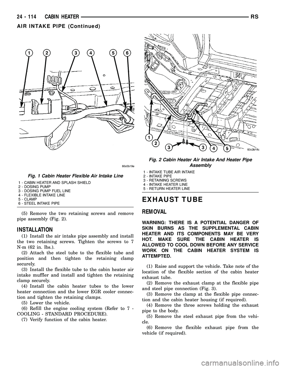
(5) Remove the two retaining screws and remove
pipe assembly (Fig. 2).
INSTALLATION
(1) Install the air intake pipe assembly and install
the two retaining screws. Tighten the screws to 7
N´m (62 in. lbs.).
(2) Attach the steel tube to the flexible tube and
position and then tighten the retaining clamp
securely.
(3) Install the flexible tube to the cabin heater air
intake muffler and install and tighten the retaining
clamp securely.
(4) Install the cabin heater tubes to the lower
heater connection and the lower EGR cooler connec-
tion and tighten the retaining clamps.
(5) Lower the vehicle.
(6) Refill the engine cooling system (Refer to 7 -
COOLING - STANDARD PROCEDURE).
(7) Verify function of the cabin heater.
EXHAUST TUBE
REMOVAL
WARNING: THERE IS A POTENTIAL DANGER OF
SKIN BURNS AS THE SUPPLEMENTAL CABIN
HEATER AND ITS COMPONENTS MAY BE VERY
HOT. MAKE SURE THE CABIN HEATER IS
ALLOWED TO COOL DOWN BEFORE ANY SERVICE
WORK ON THE CABIN HEATER SYSTEM IS
ATTEMPTED.
(1) Raise and support the vehicle. Take note of the
location of the flexible section of the cabin heater
exhaust tube.
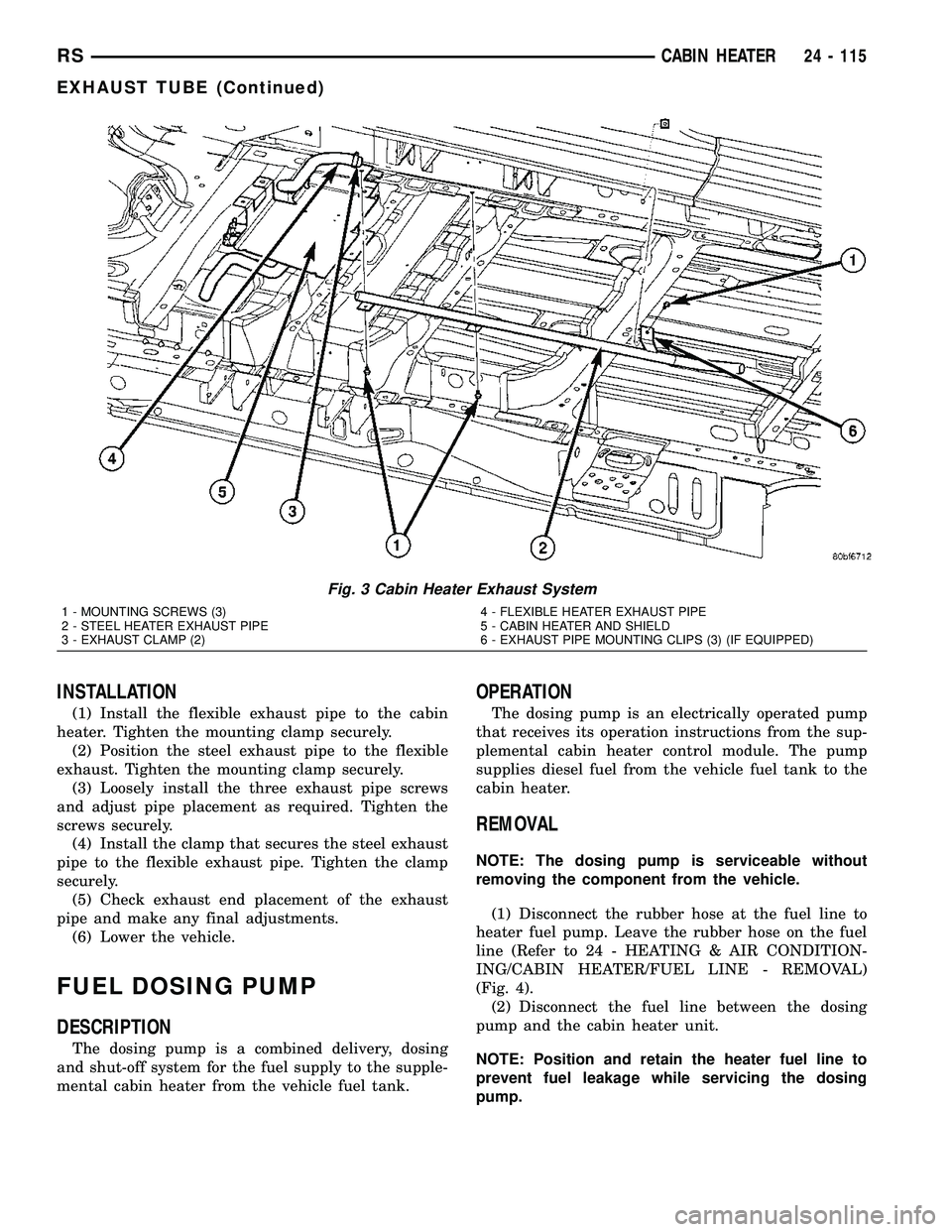
(2) Remove the exhaust clamp at the flexible pipe
and steel pipe connection (Fig. 3).
(3) Remove the clamp at the flexible pipe connec-
tion and the cabin heater housing (if required).
(4) Remove the three screws holding the exhaust
pipe to the body.
(5) Remove the steel exhaust pipe from the vehi-
cle.
(6) Remove the flexible exhaust pipe from the
vehicle (if required).
Fig. 1 Cabin Heater Flexible Air Intake Line
1 - CABIN HEATER AND SPLASH SHIELD
2 - DOSING PUMP
3 - DOSING PUMP FUEL LINE
4 - FLEXIBLE INTAKE LINE
5 - CLAMP
6 - STEEL INTAKE PIPE
Fig. 2 Cabin Heater Air Intake And Heater Pipe
Assembly
1 - INTAKE TUBE AIR INTAKE
2 - INTAKE PIPE
3 - RETAINING SCREWS
4 - INTAKE HEATER LINE
5 - RETURN HEATER LINE
24 - 114 CABIN HEATERRS
AIR INTAKE PIPE (Continued)
Page 2510 of 2585
INSTALLATION
(1) Install the flexible exhaust pipe to the cabin
heater. Tighten the mounting clamp securely.
(2) Position the steel exhaust pipe to the flexible
exhaust. Tighten the mounting clamp securely.
(3) Loosely install the three exhaust pipe screws
and adjust pipe placement as required. Tighten the
screws securely.
(4) Install the clamp that secures the steel exhaust
pipe to the flexible exhaust pipe. Tighten the clamp
securely.
(5) Check exhaust end placement of the exhaust
pipe and make any final adjustments.
(6) Lower the vehicle.
FUEL DOSING PUMP
DESCRIPTION
The dosing pump is a combined delivery, dosing
and shut-off system for the fuel supply to the supple-
mental cabin heater from the vehicle fuel tank.
OPERATION
The dosing pump is an electrically operated pump
that receives its operation instructions from the sup-
plemental cabin heater control module. The pump
supplies diesel fuel from the vehicle fuel tank to the
cabin heater.
REMOVAL
NOTE: The dosing pump is serviceable without
removing the component from the vehicle.
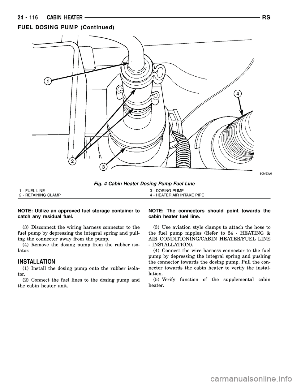
(1) Disconnect the rubber hose at the fuel line to
heater fuel pump. Leave the rubber hose on the fuel
line (Refer to 24 - HEATING & AIR CONDITION-
ING/CABIN HEATER/FUEL LINE - REMOVAL)
(Fig. 4).
(2) Disconnect the fuel line between the dosing
pump and the cabin heater unit.
NOTE: Position and retain the heater fuel line to
prevent fuel leakage while servicing the dosing
pump.
Fig. 3 Cabin Heater Exhaust System
1 - MOUNTING SCREWS (3)
2 - STEEL HEATER EXHAUST PIPE
3 - EXHAUST CLAMP (2)4 - FLEXIBLE HEATER EXHAUST PIPE
5 - CABIN HEATER AND SHIELD
6 - EXHAUST PIPE MOUNTING CLIPS (3) (IF EQUIPPED)
RSCABIN HEATER24 - 115
EXHAUST TUBE (Continued)
Page 2511 of 2585
NOTE: Utilize an approved fuel storage container to
catch any residual fuel.
(3) Disconnect the wiring harness connector to the
fuel pump by depressing the integral spring and pull-
ing the connector away from the pump.
(4) Remove the dosing pump from the rubber iso-
lator.
INSTALLATION
(1) Install the dosing pump onto the rubber isola-
tor.
(2) Connect the fuel lines to the dosing pump and
the cabin heater unit.NOTE: The connectors should point towards the
cabin heater fuel line.
(3) Use aviation style clamps to attach the hose to
the fuel pump nipples (Refer to 24 - HEATING &
AIR CONDITIONING/CABIN HEATER/FUEL LINE
- INSTALLATION).
(4) Connect the wire harness connector to the fuel
pump by depressing the integral spring and pushing
the connector towards the dosing pump. Pull the con-
nector towards the cabin heater to verify the instal-
lation.
(5) Verify function of the supplemental cabin
heater.
Fig. 4 Cabin Heater Dosing Pump Fuel Line
1 - FUEL LINE
2 - RETAINING CLAMP3 - DOSING PUMP
4 - HEATER AIR INTAKE PIPE
24 - 116 CABIN HEATERRS
FUEL DOSING PUMP (Continued)
Page 2512 of 2585
FUEL LINE
STANDARD PROCEDURE - CLEANING
(1) Remove the cabin heater fuel line (Refer to 24 -
HEATING & AIR CONDITIONING/CABIN HEAT-
ER/FUEL LINE - REMOVAL).
(2) With the cabin heater fuel line removed from
the vehicle, place a shop cloth on the fuel tank end of
the fuel line to catch any residue, then apply a small
amount of air pressure to the other end of the fuel
line.
(3) Check to see if air pressure is coming from the
tank end of the line. If pressure is flowing unre-
stricted the line is clean.
(4) If the fuel line shows any signs of being
restricted after air pressure is applied, the fuel line
should be replaced.
(5) Install the cabin heater fuel line (Refer to 24 -
HEATING & AIR CONDITIONING/CABIN HEAT-
ER/FUEL LINE - INSTALLATION).
(6) Verify function of the cabin heater.
REMOVAL
(1) Raise and support the vehicle. Take note of the
location of the flexible section of the cabin heater
exhaust tube.NOTE: Have an approved fuel holding device ready
to capture any diesel fuel that drains from the fuel
line or cabin heater unit.
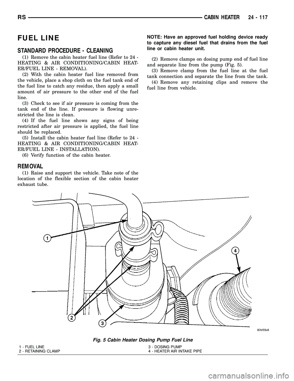
(2) Remove clamps on dosing pump end of fuel line
and separate line from the pump (Fig. 5).
(3) Remove clamp from the fuel line at the fuel
tank connection and separate the line from the tank.
(4) Remove any retaining clips and remove the
fuel line from vehicle.
Fig. 5 Cabin Heater Dosing Pump Fuel Line
1 - FUEL LINE
2 - RETAINING CLAMP3 - DOSING PUMP
4 - HEATER AIR INTAKE PIPE
RSCABIN HEATER24 - 117
Page 2513 of 2585
INSTALLATION
WARNING: DO NOT OPERATE THE DIESEL SUP-
PLEMENTAL CABIN HEATER IN AN ENCLOSED
AREA SUCH AS A GARAGE THAT DOES NOT HAVE
EXHAUST VENTILATION FACILITIES. ALWAYS VENT
THE CABIN HEATER EXHAUST WHEN OPERATING
THE CABIN HEATER. ALLOW THE DIESEL SUPPLE-
MENTAL CABIN HEATER TO COOL BEFORE PER-
FORMING ANY SERVICE PROCEDURES TO THE
CABIN HEATER. VERIFY THAT ALL DIESEL SUP-
PLEMENTAL CABIN HEATER FUEL LINES ARE
SECURELY FASTENED TO THEIR RESPECTIVE
COMPONENTS BEFORE PERFORMING ANY SER-
VICE PROCEDURES TO THE CABIN HEATER. FAIL-
URE TO FOLLOW THESE INSTRUCTION MAY
RESULT IN PERSONAL INJURY OR DEATH.
NOTE: Verify that there is more than 1/8 of a tank of
fuel in the vehicle's fuel tank before performing this
procedure. Add fuel, if necessary.
(1) Install the cabin heater fuel supply line into
vehicle and fuel line retainers.
(2) Install the fuel line connection at the fuel tank
and tighten the connection securely.
(3) Install the fuel line at the dosing pump and
tighten the connection securely.
(4) Lower the vehicle.
NOTE: Failure to prime the dosing pump after drain-
ing the supplemental cabin fuel line will prevent
cabin heater activation during the first attempt to
start the cabin heater. This will also set a diagnostic
trouble code (DTC) in the cabin heater control's
memory. Do not perform the Dosing Pump Priming
procedure if an attempt was made to start the cabin
heater without priming the dosing pump first. This
will put excess fuel in the cabin heater and cause
smoke to emit from the cabin heater exhaust pipe
when cabin heater activation occurs.
(5) Connect the DRBIIItscan tool to the diagnos-
tic link connector.
(6) Turn the ignition to the ON position.
NOTE: Do not activate the dosing pump prime more
than one time. This will put excess fuel in the sup-
plemental cabin heater and cause smoke to emit
from the cabin heater exhaust pipe when cabin
heater activation occurs.
NOTE: A clicking noise heard coming from the dos-
ing pump indicates that the pump is operational.(7) With the DRBIIItscan tool in Cabin Heater,
select System Tests and Dosing Pump Prime. Allow
the dosing pump to run for the full 45 second cycle
time. When the 45 second cycle is complete, press
Page Back on the DRBIIItscan tool key pad to exit
the Dosing Pump Prime. The Dosing Pump Priming
procedure is now complete.
HEATER UNIT
REMOVAL
WARNING: DO NOT OPERATE THE DIESEL SUP-
PLEMENTAL CABIN HEATER IN AN ENCLOSED
AREA SUCH AS A GARAGE THAT DOES NOT HAVE
EXHAUST VENTILATION FACILITIES. ALWAYS VENT
THE CABIN HEATER EXHAUST WHEN OPERATING
THE CABIN HEATER. ALLOW THE DIESEL SUPPLE-
MENTAL CABIN HEATER TO COOL BEFORE PER-
FORMING ANY SERVICE PROCEDURES TO THE
CABIN HEATER. VERIFY THAT ALL DIESEL SUP-
PLEMENTAL CABIN HEATER FUEL LINES ARE
SECURELY FASTENED TO THEIR RESPECTIVE
COMPONENTS BEFORE PERFORMING ANY SER-
VICE PROCEDURES TO THE CABIN HEATER. FAIL-
URE TO FOLLOW THESE INSTRUCTION MAY
RESULT IN PERSONAL INJURY OR DEATH.
(1) Raise and support the vehicle. Take note of the
location of the flexible section of the cabin heater
exhaust tube.
(2) Drain the engine cooling system (Refer to 7 -
COOLING - STANDARD PROCEDURE).
(3) Carefully open one hose to the underbody tube
assembly and drain the remaining coolant. A salvage
hose is a good idea to control the residual coolant, as
flow will occur from both the cabin heater and the
hose and tube assemblies.
(4) Remove the second hose from the underbody
hose and tube assembly.
(5) Loosen the hose and tube assembly from the
toe-board crossmember at two locations.
(6) Disconnect the electrical connector from the
body harness near the toe-board crossmember and
rail.
(7) Remove the wiring harness from the toe-board
crossmember (Refer to 24 - HEATING & AIR CON-
DITIONING/CABIN HEATER/HEATER UNIT -
REMOVAL).
(8) Open the fuel filler cap. Disconnect the rubber
fuel hose between the body tube assembly and the
fuel pump nipple at the body tube joint. A minimal
amount of fuel may flow from the open port.
NOTE: Utilize an approved fuel storage container to
catch any residual fuel.
24 - 118 CABIN HEATERRS
FUEL LINE (Continued)