2004 CHRYSLER VOYAGER OUTLET
[x] Cancel search: OUTLETPage 1167 of 2585
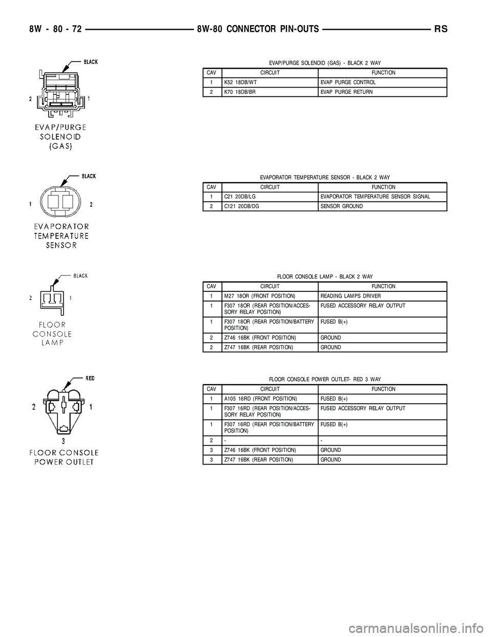
EVAP/PURGE SOLENOID (GAS) - BLACK 2 WAY
CAV CIRCUIT FUNCTION
1 K52 18DB/WT EVAP PURGE CONTROL
2 K70 18DB/BR EVAP PURGE RETURN
EVAPORATOR TEMPERATURE SENSOR - BLACK 2 WAY
CAV CIRCUIT FUNCTION
1 C21 20DB/LG EVAPORATOR TEMPERATURE SENSOR SIGNAL
2 C121 20DB/DG SENSOR GROUND
FLOOR CONSOLE LAMP - BLACK 2 WAY
CAV CIRCUIT FUNCTION
1 M27 18OR (FRONT POSITION) READING LAMPS DRIVER
1 F307 18OR (REAR POSITION/ACCES-
SORY RELAY POSITION)FUSED ACCESSORY RELAY OUTPUT
1 F307 18OR (REAR POSITION/BATTERY
POSITION)FUSED B(+)
2 Z746 16BK (FRONT POSITION) GROUND
2 Z747 16BK (REAR POSITION) GROUND
FLOOR CONSOLE POWER OUTLET- RED 3 WAY
CAV CIRCUIT FUNCTION
1 A105 16RD (FRONT POSITION) FUSED B(+)
1 F307 16RD (REAR POSITION/ACCES-
SORY RELAY POSITION)FUSED ACCESSORY RELAY OUTPUT
1 F307 16RD (REAR POSITION/BATTERY
POSITION)FUSED B(+)
2- -
3 Z746 16BK (FRONT POSITION) GROUND
3 Z747 16BK (REAR POSITION) GROUND
8W - 80 - 72 8W-80 CONNECTOR PIN-OUTSRS
Page 1204 of 2585
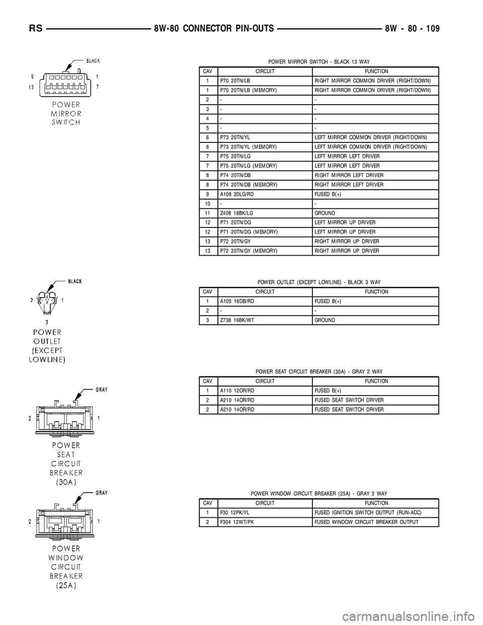
POWER MIRROR SWITCH - BLACK 13 WAY
CAV CIRCUIT FUNCTION
1 P70 20TN/LB RIGHT MIRROR COMMON DRIVER (RIGHT/DOWN)
1 P70 20TN/LB (MEMORY) RIGHT MIRROR COMMON DRIVER (RIGHT/DOWN)
2- -
3- -
4- -
5- -
6 P73 20TN/YL LEFT MIRROR COMMON DRIVER (RIGHT/DOWN)
6 P73 20TN/YL (MEMORY) LEFT MIRROR COMMON DRIVER (RIGHT/DOWN)
7 P75 20TN/LG LEFT MIRROR LEFT DRIVER
7 P75 20TN/LG (MEMORY) LEFT MIRROR LEFT DRIVER
8 P74 20TN/DB RIGHT MIRROR LEFT DRIVER
8 P74 20TN/DB (MEMORY) RIGHT MIRROR LEFT DRIVER
9 A108 20LG/RD FUSED B(+)
10 - -
11 Z408 18BK/LG GROUND
12 P71 20TN/DG LEFT MIRROR UP DRIVER
12 P71 20TN/DG (MEMORY) LEFT MIRROR UP DRIVER
13 P72 20TN/GY RIGHT MIRROR UP DRIVER
13 P72 20TN/GY (MEMORY) RIGHT MIRROR UP DRIVER
POWER OUTLET (EXCEPT LOWLINE) - BLACK 3 WAY
CAV CIRCUIT FUNCTION
1 A105 16DB/RD FUSED B(+)
2- -
3 Z738 16BK/WT GROUND
POWER SEAT CIRCUIT BREAKER (30A) - GRAY 2 WAY
CAV CIRCUIT FUNCTION
1 A110 12OR/RD FUSED B(+)
2 A210 14OR/RD FUSED SEAT SWITCH DRIVER
2 A210 14OR/RD FUSED SEAT SWITCH DRIVER
POWER WINDOW CIRCUIT BREAKER (25A) - GRAY 2 WAY
CAV CIRCUIT FUNCTION
1 F30 12PK/YL FUSED IGNITION SWITCH OUTPUT (RUN-ACC)
2 F304 12WT/PK FUSED WINDOW CIRCUIT BREAKER OUTPUT
RS8W-80 CONNECTOR PIN-OUTS8W - 80 - 109
Page 1214 of 2585
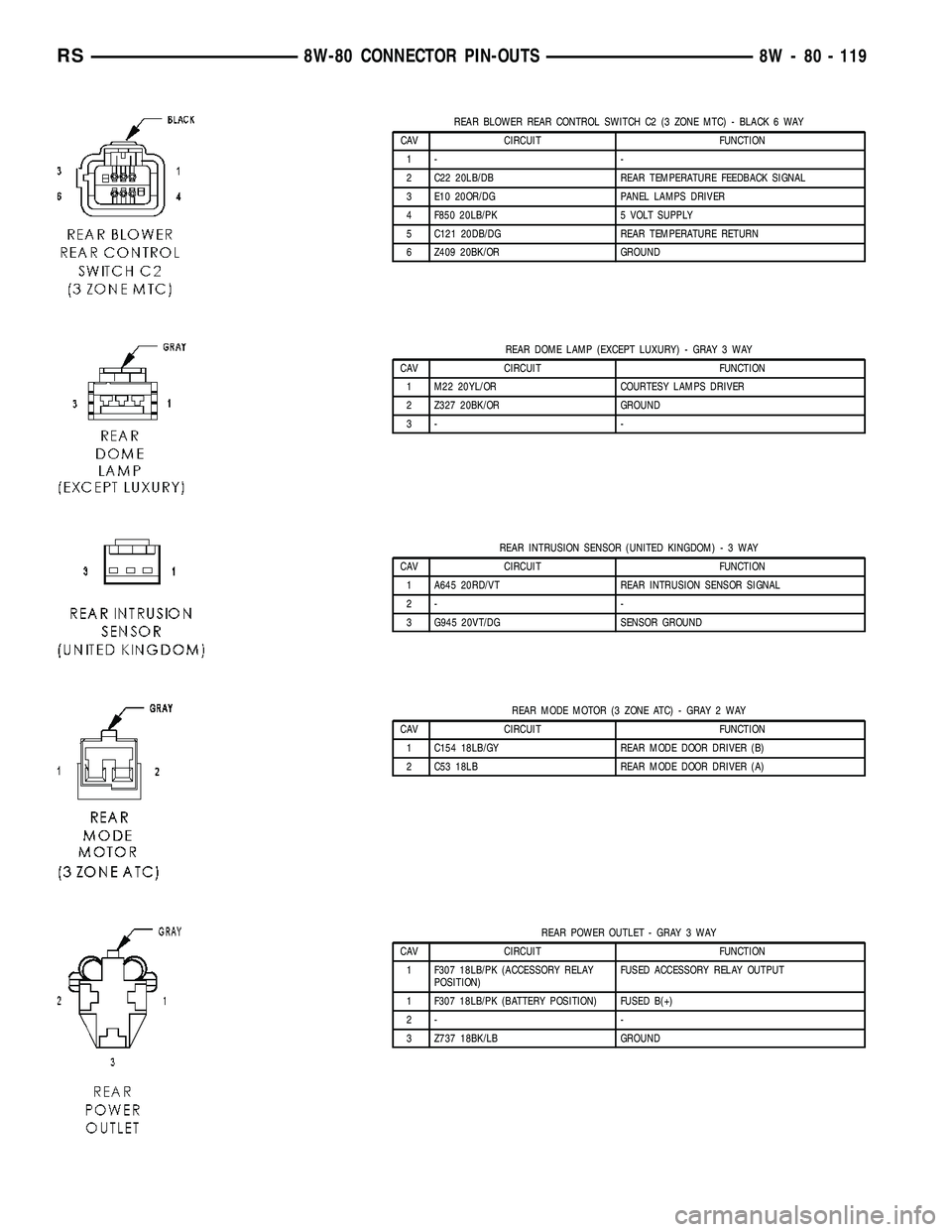
REAR BLOWER REAR CONTROL SWITCH C2 (3 ZONE MTC) - BLACK 6 WAY
CAV CIRCUIT FUNCTION
1- -
2 C22 20LB/DB REAR TEMPERATURE FEEDBACK SIGNAL
3 E10 20OR/DG PANEL LAMPS DRIVER
4 F850 20LB/PK 5 VOLT SUPPLY
5 C121 20DB/DG REAR TEMPERATURE RETURN
6 Z409 20BK/OR GROUND
REAR DOME LAMP (EXCEPT LUXURY) - GRAY 3 WAY
CAV CIRCUIT FUNCTION
1 M22 20YL/OR COURTESY LAMPS DRIVER
2 Z327 20BK/OR GROUND
3- -
REAR INTRUSION SENSOR (UNITED KINGDOM)-3WAY
CAV CIRCUIT FUNCTION
1 A645 20RD/VT REAR INTRUSION SENSOR SIGNAL
2- -
3 G945 20VT/DG SENSOR GROUND
REAR MODE MOTOR (3 ZONE ATC) - GRAY 2 WAY
CAV CIRCUIT FUNCTION
1 C154 18LB/GY REAR MODE DOOR DRIVER (B)
2 C53 18LB REAR MODE DOOR DRIVER (A)
REAR POWER OUTLET - GRAY 3 WAY
CAV CIRCUIT FUNCTION
1 F307 18LB/PK (ACCESSORY RELAY
POSITION)FUSED ACCESSORY RELAY OUTPUT
1 F307 18LB/PK (BATTERY POSITION) FUSED B(+)
2- -
3 Z737 18BK/LB GROUND
RS8W-80 CONNECTOR PIN-OUTS8W - 80 - 119
Page 1236 of 2585
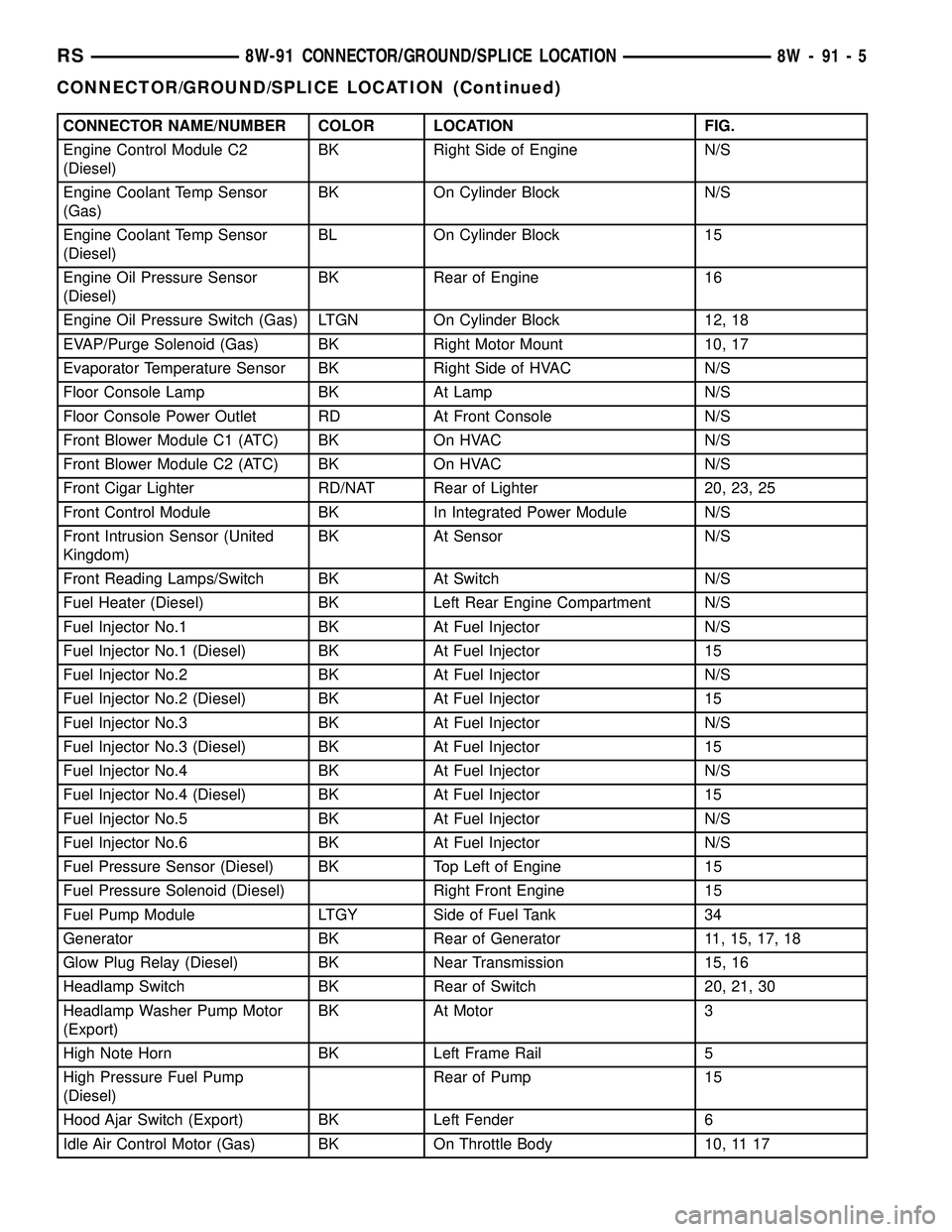
CONNECTOR NAME/NUMBER COLOR LOCATION FIG.
Engine Control Module C2
(Diesel)BK Right Side of Engine N/S
Engine Coolant Temp Sensor
(Gas)BK On Cylinder Block N/S
Engine Coolant Temp Sensor
(Diesel)BL On Cylinder Block 15
Engine Oil Pressure Sensor
(Diesel)BK Rear of Engine 16
Engine Oil Pressure Switch (Gas) LTGN On Cylinder Block 12, 18
EVAP/Purge Solenoid (Gas) BK Right Motor Mount 10, 17
Evaporator Temperature Sensor BK Right Side of HVAC N/S
Floor Console Lamp BK At Lamp N/S
Floor Console Power Outlet RD At Front Console N/S
Front Blower Module C1 (ATC) BK On HVAC N/S
Front Blower Module C2 (ATC) BK On HVAC N/S
Front Cigar Lighter RD/NAT Rear of Lighter 20, 23, 25
Front Control Module BK In Integrated Power Module N/S
Front Intrusion Sensor (United
Kingdom)BK At Sensor N/S
Front Reading Lamps/Switch BK At Switch N/S
Fuel Heater (Diesel) BK Left Rear Engine Compartment N/S
Fuel Injector No.1 BK At Fuel Injector N/S
Fuel Injector No.1 (Diesel) BK At Fuel Injector 15
Fuel Injector No.2 BK At Fuel Injector N/S
Fuel Injector No.2 (Diesel) BK At Fuel Injector 15
Fuel Injector No.3 BK At Fuel Injector N/S
Fuel Injector No.3 (Diesel) BK At Fuel Injector 15
Fuel Injector No.4 BK At Fuel Injector N/S
Fuel Injector No.4 (Diesel) BK At Fuel Injector 15
Fuel Injector No.5 BK At Fuel Injector N/S
Fuel Injector No.6 BK At Fuel Injector N/S
Fuel Pressure Sensor (Diesel) BK Top Left of Engine 15
Fuel Pressure Solenoid (Diesel) Right Front Engine 15
Fuel Pump Module LTGY Side of Fuel Tank 34
Generator BK Rear of Generator 11, 15, 17, 18
Glow Plug Relay (Diesel) BK Near Transmission 15, 16
Headlamp Switch BK Rear of Switch 20, 21, 30
Headlamp Washer Pump Motor
(Export)BK At Motor 3
High Note Horn BK Left Frame Rail 5
High Pressure Fuel Pump
(Diesel)Rear of Pump 15
Hood Ajar Switch (Export) BK Left Fender 6
Idle Air Control Motor (Gas) BK On Throttle Body 10, 11 17
RS8W-91 CONNECTOR/GROUND/SPLICE LOCATION8W-91-5
CONNECTOR/GROUND/SPLICE LOCATION (Continued)
Page 1240 of 2585
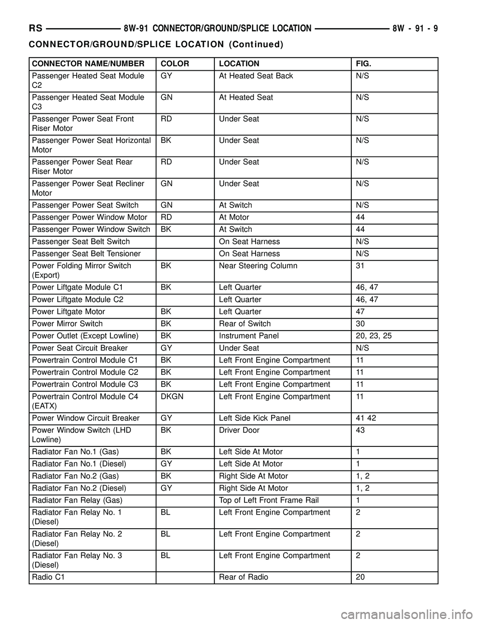
CONNECTOR NAME/NUMBER COLOR LOCATION FIG.
Passenger Heated Seat Module
C2GY At Heated Seat Back N/S
Passenger Heated Seat Module
C3GN At Heated Seat N/S
Passenger Power Seat Front
Riser MotorRD Under Seat N/S
Passenger Power Seat Horizontal
MotorBK Under Seat N/S
Passenger Power Seat Rear
Riser MotorRD Under Seat N/S
Passenger Power Seat Recliner
MotorGN Under Seat N/S
Passenger Power Seat Switch GN At Switch N/S
Passenger Power Window Motor RD At Motor 44
Passenger Power Window Switch BK At Switch 44
Passenger Seat Belt Switch On Seat Harness N/S
Passenger Seat Belt Tensioner On Seat Harness N/S
Power Folding Mirror Switch
(Export)BK Near Steering Column 31
Power Liftgate Module C1 BK Left Quarter 46, 47
Power Liftgate Module C2 Left Quarter 46, 47
Power Liftgate Motor BK Left Quarter 47
Power Mirror Switch BK Rear of Switch 30
Power Outlet (Except Lowline) BK Instrument Panel 20, 23, 25
Power Seat Circuit Breaker GY Under Seat N/S
Powertrain Control Module C1 BK Left Front Engine Compartment 11
Powertrain Control Module C2 BK Left Front Engine Compartment 11
Powertrain Control Module C3 BK Left Front Engine Compartment 11
Powertrain Control Module C4
(EATX)DKGN Left Front Engine Compartment 11
Power Window Circuit Breaker GY Left Side Kick Panel 41 42
Power Window Switch (LHD
Lowline)BK Driver Door 43
Radiator Fan No.1 (Gas) BK Left Side At Motor 1
Radiator Fan No.1 (Diesel) GY Left Side At Motor 1
Radiator Fan No.2 (Gas) BK Right Side At Motor 1, 2
Radiator Fan No.2 (Diesel) GY Right Side At Motor 1, 2
Radiator Fan Relay (Gas) Top of Left Front Frame Rail 1
Radiator Fan Relay No. 1
(Diesel)BL Left Front Engine Compartment 2
Radiator Fan Relay No. 2
(Diesel)BL Left Front Engine Compartment 2
Radiator Fan Relay No. 3
(Diesel)BL Left Front Engine Compartment 2
Radio C1 Rear of Radio 20
RS8W-91 CONNECTOR/GROUND/SPLICE LOCATION8W-91-9
CONNECTOR/GROUND/SPLICE LOCATION (Continued)
Page 1241 of 2585
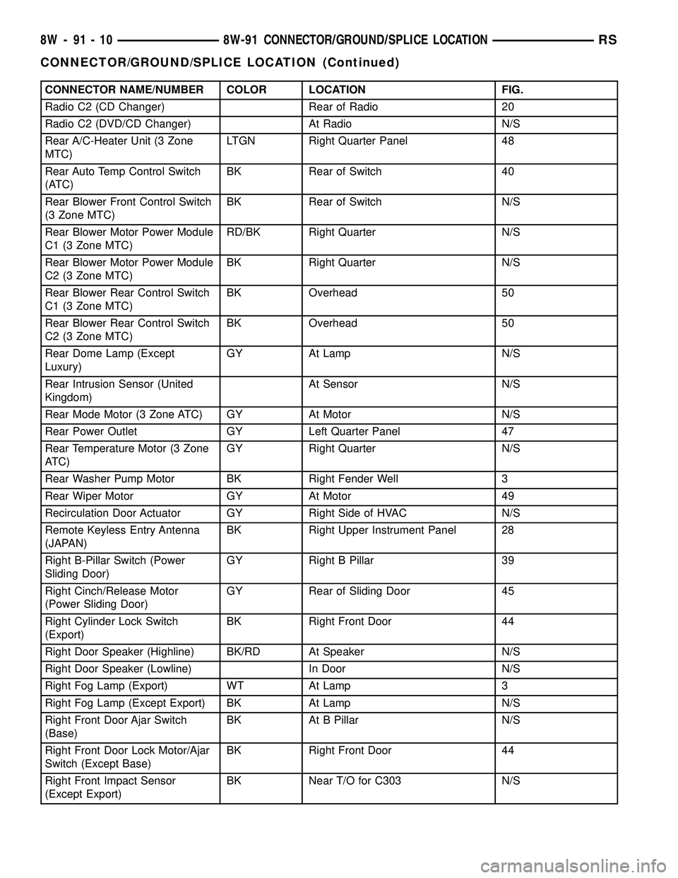
CONNECTOR NAME/NUMBER COLOR LOCATION FIG.
Radio C2 (CD Changer) Rear of Radio 20
Radio C2 (DVD/CD Changer) At Radio N/S
Rear A/C-Heater Unit (3 Zone
MTC)LTGN Right Quarter Panel 48
Rear Auto Temp Control Switch
(ATC)BK Rear of Switch 40
Rear Blower Front Control Switch
(3 Zone MTC)BK Rear of Switch N/S
Rear Blower Motor Power Module
C1 (3 Zone MTC)RD/BK Right Quarter N/S
Rear Blower Motor Power Module
C2 (3 Zone MTC)BK Right Quarter N/S
Rear Blower Rear Control Switch
C1 (3 Zone MTC)BK Overhead 50
Rear Blower Rear Control Switch
C2 (3 Zone MTC)BK Overhead 50
Rear Dome Lamp (Except
Luxury)GY At Lamp N/S
Rear Intrusion Sensor (United
Kingdom)At Sensor N/S
Rear Mode Motor (3 Zone ATC) GY At Motor N/S
Rear Power Outlet GY Left Quarter Panel 47
Rear Temperature Motor (3 Zone
ATC)GY Right Quarter N/S
Rear Washer Pump Motor BK Right Fender Well 3
Rear Wiper Motor GY At Motor 49
Recirculation Door Actuator GY Right Side of HVAC N/S
Remote Keyless Entry Antenna
(JAPAN)BK Right Upper Instrument Panel 28
Right B-Pillar Switch (Power
Sliding Door)GY Right B Pillar 39
Right Cinch/Release Motor
(Power Sliding Door)GY Rear of Sliding Door 45
Right Cylinder Lock Switch
(Export)BK Right Front Door 44
Right Door Speaker (Highline) BK/RD At Speaker N/S
Right Door Speaker (Lowline) In Door N/S
Right Fog Lamp (Export) WT At Lamp 3
Right Fog Lamp (Except Export) BK At Lamp N/S
Right Front Door Ajar Switch
(Base)BK At B Pillar N/S
Right Front Door Lock Motor/Ajar
Switch (Except Base)BK Right Front Door 44
Right Front Impact Sensor
(Except Export)BK Near T/O for C303 N/S
8W - 91 - 10 8W-91 CONNECTOR/GROUND/SPLICE LOCATIONRS
CONNECTOR/GROUND/SPLICE LOCATION (Continued)
Page 1292 of 2585
8W-97 POWER DISTRIBUTION SYSTEM
TABLE OF CONTENTS
page page
POWER DISTRIBUTION SYSTEM
DESCRIPTION..........................1
OPERATION............................1
SPECIAL TOOLS
POWER DISTRIBUTION SYSTEMS.........1
INTEGRATED POWER MODULE
DESCRIPTION..........................2
OPERATION............................2
REMOVAL.............................2
INSTALLATION..........................3IOD FUSE
DESCRIPTION..........................3
OPERATION............................3
POWER OUTLET
DESCRIPTION..........................4
OPERATION............................4
DIAGNOSIS AND TESTING
DIAGNOSIS & TESTING - POWER OUTLET . . 4
REMOVAL.............................5
INSTALLATION..........................5
POWER DISTRIBUTION
SYSTEM
DESCRIPTION
This group covers the various standard and
optional power distribution components used on this
model. The power distribution system for this vehicle
consists of the following components:
²Integrated Power Module (IPM)
²Front Control Module (FCM)
²Power Outlets
Refer to Wiring Diagrams for complete circuit sche-
matics.
The power distribution system also incorporates
various types of circuit control and protection fea-
tures, including:
²Automatic resetting circuit breakers
²Blade-type fuses
²Bus bars
²Cartridge fuses
²Circuit splice blocks
²Flashers
²Fusible links
²Relays
Following are general descriptions of the major
components in the power distribution system. See the
owner's manual in the vehicle glove box for more
information on the features and use of all of the
power distribution system components.
OPERATION
The power distribution system for this vehicle is
designed to provide safe, reliable, and centralized dis-
tribution points for the electrical current required to
operate all of the many standard and optional facto-
ry-installed electrical and electronic powertrain,
chassis, safety, security, comfort and convenience sys-
tems. At the same time, the power distribution sys-
tem was designed to provide ready access to these
electrical distribution points for the vehicle techni-
cian to use when conducting diagnosis and repair of
faulty circuits. The power distribution system can
also prove useful for the sourcing of additional elec-
trical circuits that may be required to provide the
electrical current needed to operate many accessories
that the vehicle owner may choose to have installed
in the aftermarket.
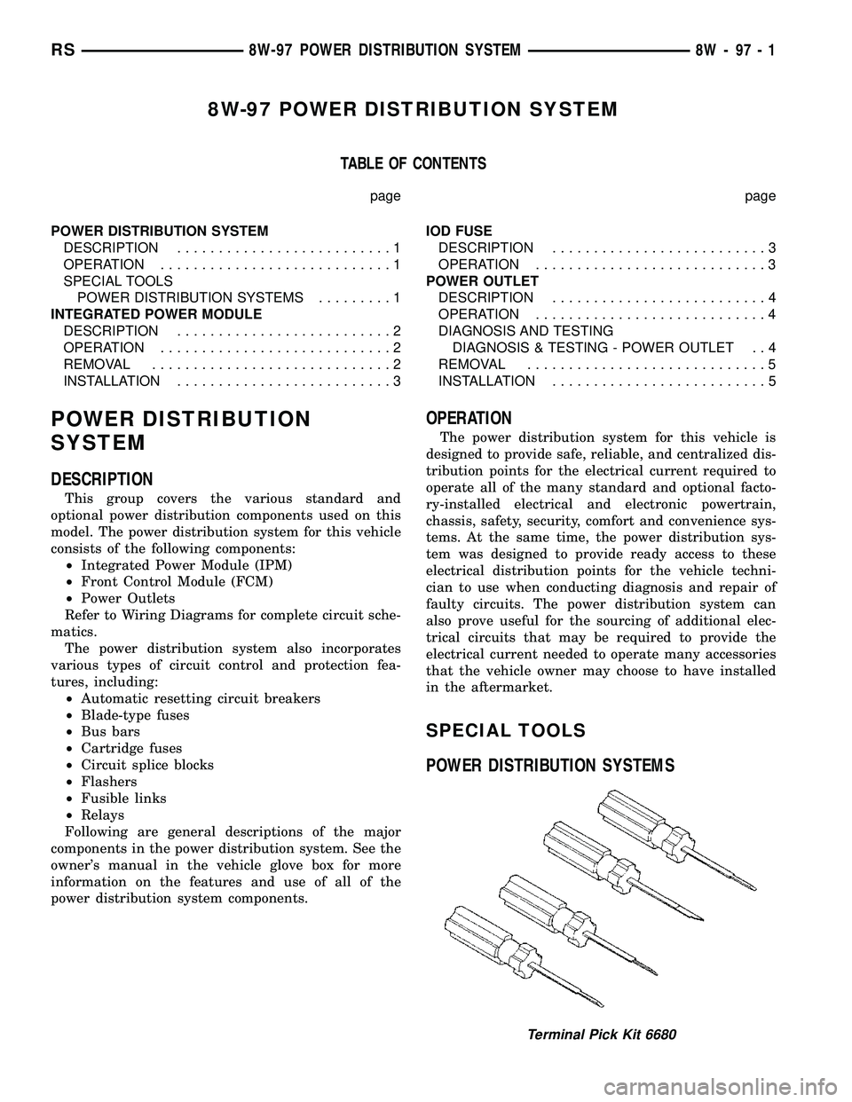
SPECIAL TOOLS
POWER DISTRIBUTION SYSTEMS
Terminal Pick Kit 6680
RS8W-97 POWER DISTRIBUTION SYSTEM8W-97-1
Page 1295 of 2585
POWER OUTLET
DESCRIPTION
Accessory power outlets are standard equipment on
this model. Two power outlets are installed in the
instrument panel center lower bezel, which is located
near the bottom of the instrument panel center stack
area. Two additional power outlets are also incorpo-
rated into the vehicle, one on the left rear C-pillar
trim and the other in the center console, if equipped.
The power outlets bases are secured by a snap fit in
the appropriate bezels. A hinged plug flips closed to
conceal and protect the power outlet base when the
power outlet is not being used.
The power outlet receptacle unit and the power
outlet plugs are each available for service replace-
ment.
OPERATION
The power outlet base or receptacle shell is con-
nected to ground, and an insulated contact in the
bottom of the shell is connected to battery current.
The power outlet on the instrument panel marked
with a battery receives battery voltage from a fuse in
the Integrated Power Module (IPM) at all times. The
other power outlet on the instrument panel marked
with a key receives battery voltage only when the
key is in the on position.
The power outlet located in the center console
receives battery voltage all the time when positioned
between thefront seatsand key-on voltage when
positioned between therear seats. The power outlet
located on the C-pillar receives battery voltage only
when the key is in the on position.
DIAGNOSIS AND TESTING
DIAGNOSIS & TESTING - POWER OUTLET
For complete circuit diagrams, refer toCigar
Lighter/Power Outletin Wiring Diagrams.
WARNING: ON VEHICLES EQUIPPED WITH AIR-
BAGS, REFER TO RESTRAINTS BEFORE ATTEMPT-
ING ANY STEERING WHEEL, STEERING COLUMN,
SEAT OR INSTRUMENT PANEL COMPONENT DIAG-
NOSIS OR SERVICE. FAILURE TO TAKE THE
PROPER PRECAUTIONS COULD RESULT IN ACCI-
DENTAL AIRBAG DEPLOYMENT AND POSSIBLE
PERSONAL INJURY.
(1) Check the fused B(+) fuse in the Integrated
Power Module (IPM). If OK, go to Step 2. If not OK,
repair the shorted circuit or component as required
and replace the faulty fuse.
(2) Check for battery voltage at the fused B(+) fuse
in the IPM. If OK, go to Step 3. If not OK, repair the
open fused B(+) circuit to the IPM fuse as required.
(3) Open the power outlet door. Check for continu-
ity between the inside circumference of the power
outlet receptacle and a good ground. There should be
continuity. If OK, go to Step 4. If not OK, go to Step
5.
(4) Check for battery voltage at the insulated con-
tact located at the back of the power outlet recepta-
cle. If not OK, go to Step 5.
(5) Disconnect and isolate the battery negative
cable. Remove the appropriate bezel. Check for conti-
nuity between the ground circuit cavity of the power
outlet wire harness connector and a good ground.
There should be continuity. If OK, go to Step 6. If not
OK, repair the open ground circuit to ground as
required.
(6) Connect the battery negative cable. Check for
battery voltage at the fused B(+) circuit cavity of the
power outlet wire harness connector. If OK, replace
the faulty power outlet receptacle. If not OK, repair
the open fused B(+) circuit to the IPM fuse as
required.
8W - 97 - 4 8W-97 POWER DISTRIBUTION SYSTEMRS