2004 CHRYSLER VOYAGER engine
[x] Cancel search: enginePage 1593 of 2585
CAUTION: Use care not to bend tube ends of the
power steering hoses when installing. Leaks and
restrictions may occur.
CAUTION: Power steering fluid hoses must remain
away from the exhaust system and must not come
in contact with any unfriendly surfaces on the vehi-
cle.
(4) Route hose up behind engine toward pump
avoiding tight bends or kinking.
(5) Install power steering pressure hose end into
pump pressure outlet fitting (Fig. 21). Thread tube
nut into outlet fitting, but do not tighten at this time.
(6) Attach pressure hose routing bracket to engine
(Fig. 21). Tighten bolt to 23 N´m (200 in. lbs.) torque.
(7) Tighten hose tube nut at pump outlet fitting to
31 N´m (275 in. lbs.) torque.
(8) Route hose behind cradle crossmember and
start hose end into gear port. Do not tighten hose
tube nut at this time.
(9) Attach hose to suspension cradle crossmember
and steel reinforcement using two routing clamps
and bolts (Fig. 20). Tighten clamp bolt at steel rein-
forcement to 11 N´m (100 in. lbs.) torque. Tighten
clamp bolt at cradle crossmember to 23 N´m (200 in.
lbs.) torque.
(10) Tighten hose tube nut at power steering gear
port to 31 N´m (275 in. lbs.) torque.
(11) Install front emissions vapor canister. (Refer
to 25 - EMISSIONS CONTROL/EVAPORATIVE
EMISSIONS/VAPOR CANISTER - INSTALLATION)
(12) Lower vehicle.
(13) Fill and bleed the power steering system
using the Power Steering Pump Initial Operation
Procedure. (Refer to 19 - STEERING/PUMP - STAN-
DARD PROCEDURE)
(14) Inspect system for leaks.
HOSE - POWER STEERING
RETURN
REMOVAL
REMOVAL - 2.4L ENGINE
NOTE: Before proceeding, review all WARNINGS
and CAUTIONS. (Refer to 19 - STEERING/PUMP -
WARNING)(Refer to 19 - STEERING/PUMP - CAU-
TION)
(1) Remove cap from power steering fluid reser-
voir.(2) Using a siphon pump, remove as much power
steering fluid as possible from power steering fluid
reservoir.
(3) Raise vehicle. (Refer to LUBRICATION &
MAINTENANCE/HOISTING - STANDARD PROCE-
DURE)
(4) Remove front emissions vapor canister. (Refer
to 25 - EMISSIONS CONTROL/EVAPORATIVE
EMISSIONS/VAPOR CANISTER - REMOVAL)
(5) Place an oil drain pan under vehicle to catch
power steering fluid.
(6) Cut tie-strap securing insulating heat sleeve to
power steering fluid return hose near power steering
pump. Pull back heat sleeve to expose hose clamp.
(7) Remove clamp, then return hose from power
steering pump (Fig. 19).
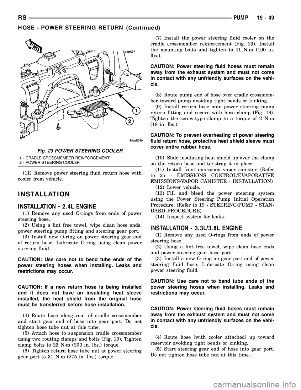
(8) Remove 2 bolts attaching power steering cooler
to cradle crossmember reinforcement (Fig. 23).
(9) Remove bolts attaching routing clamps to front
suspension cradle crossmember (Fig. 19). Remove
return hose from clamps.
(10) Back out return hose tube nut at power steer-
ing gear and remove hose (Fig. 19).
REMOVAL - 3.3L/3.8L ENGINE
NOTE: Before proceeding, review all WARNINGS
and CAUTIONS. (Refer to 19 - STEERING/PUMP -
WARNING)(Refer to 19 - STEERING/PUMP - CAU-
TION)
(1) Remove cap from power steering fluid reser-
voir.
(2) Using a siphon pump, remove as much power
steering fluid as possible from power steering fluid
reservoir.
(3) Place an oil drain pan under vehicle to catch
any draining power steering fluid.
(4) Remove clamp attaching return hose to power
steering fluid reservoir. Disconnect hose from reser-
voir (Fig. 21).
(5) Follow return hose downward and open
retainer at ABS bracket (Fig. 20). Remove hose tube
from retainer.
(6) Raise vehicle. (Refer to LUBRICATION &
MAINTENANCE/HOISTING - STANDARD PROCE-
DURE)
(7) Remove front emissions vapor canister. (Refer
to 25 - EMISSIONS CONTROL/EVAPORATIVE
EMISSIONS/VAPOR CANISTER - REMOVAL)
(8) Remove bolt securing return hose routing
clamp to suspension cradle crossmember (Fig. 20).
(9) Remove 2 bolts attaching power steering cooler
to cradle crossmember reinforcement (Fig. 23).
(10) Disconnect return hose at power steering gear
(Fig. 20).
19 - 48 PUMPRS
HOSE - POWER STEERING PRESSURE (Continued)
Page 1594 of 2585
(11) Remove power steering fluid return hose with
cooler from vehicle.
INSTALLATION
INSTALLATION - 2.4L ENGINE
(1) Remove any used O-rings from ends of power
steering hose.
(2) Using a lint free towel, wipe clean hose ends,
power steering pump fitting and steering gear port.
(3) Install new O-ring on power steering gear end
of return hose. Lubricate O-ring using clean power
steering fluid.
CAUTION: Use care not to bend tube ends of the
power steering hoses when installing. Leaks and
restrictions may occur.
CAUTION: If a new return hose is being installed
and it does not have an insulating heat sleeve
installed, the heat shield from the original hose
must be transferred before hose installation.
(4) Route hose along rear of cradle crossmember
and start gear end of hose into gear port. Do not
tighten hose tube nut at this time.
(5) Attach hose to suspension cradle crossmember
using two routing clamps and bolts (Fig. 19). Tighten
clamp bolts to 23 N´m (200 in. lbs.) torque.
(6) Tighten return hose tube nut at power steering
gear port to 31 N´m (275 in. lbs.) torque.(7) Install the power steering fluid cooler on the
cradle crossmember reinforcement (Fig. 23). Install
the mounting bolts and tighten to 11 N´m (100 in.
lbs.).
CAUTION: Power steering fluid hoses must remain
away from the exhaust system and must not come
in contact with any unfriendly surfaces on the vehi-
cle.
(8) Route pump end of hose over cradle crossmem-
ber toward pump avoiding tight bends or kinking.
(9) Install return hose onto power steering pump
return fitting and secure with hose clamp (Fig. 19).
Tighten the screw-type clamp to a torque of 2 N´m
(18 in. lbs.).
CAUTION: To prevent overheating of power steering
fluid return hose, protective heat shield sleeve must
cover entire rubber hose.
(10) Slide insulating heat shield up over the clamp
on the return hose and tie-strap it in place.
(11) Install front emissions vapor canister. (Refer
to 25 - EMISSIONS CONTROL/EVAPORATIVE
EMISSIONS/VAPOR CANISTER - INSTALLATION)
(12) Lower vehicle.
(13) Fill and bleed the power steering system
using the Power Steering Pump Initial Operation
Procedure. (Refer to 19 - STEERING/PUMP - STAN-
DARD PROCEDURE)
(14) Inspect system for leaks.
INSTALLATION - 3.3L/3.8L ENGINE
(1) Remove any used O-rings from ends of power
steering hose.
(2) Using a lint free towel, wipe clean hose ends
and power steering gear hose port.
(3) Install a new O-ring on gear port end of power
steering fluid hose. Lubricate O-ring using clean
power steering fluid.
CAUTION: Use care not to bend tube ends of the
power steering hoses when installing. Leaks and
restrictions may occur.
CAUTION: Power steering fluid hoses must remain
away from the exhaust system and must not come
in contact with any unfriendly surfaces on the vehi-
cle.
(4) Route hose (with cooler attached) up toward
reservoir avoiding tight bends or kinking.
(5) Start steering gear end of hose into gear port.
Do not tighten hose tube nut at this time.
Fig. 23 POWER STEERING COOLER
1 - CRADLE CROSSMEMBER REINFORCEMENT
2 - POWER STEERING COOLER
RSPUMP19-49
HOSE - POWER STEERING RETURN (Continued)
Page 1595 of 2585
(6) Attach return hose tubes to suspension cradle
crossmember using routing clamp and bolt (Fig. 20).
Tighten clamp bolt to 23 N´m (200 in. lbs.) torque.
(7) Install the power steering fluid cooler on the
cradle crossmember reinforcement (Fig. 23). Install
the mounting bolts and tighten to 11 N´m (100 in.
lbs.). When installing mounting bolts, include pres-
sure hose routing clamp.
(8) Tighten hose tube nut at power steering gear
port to 31 N´m (275 in. lbs.) torque.
(9) Install front emissions vapor canister. (Refer to
25 - EMISSIONS CONTROL/EVAPORATIVE EMIS-
SIONS/VAPOR CANISTER - INSTALLATION)
(10) Lower vehicle.
(11) Install return hose tube into retainer on ABS
bracket (Fig. 20). Close the bracket.
(12) Install return hose onto reservoir (Fig. 21).
Slide the hose clamp into position on fluid reservoir
and attach it.Be sure hose clamp in installed
past bead on fluid reservoir fitting.
(13) Fill and bleed power steering system using
the Power Steering Pump Initial Operation Proce-
dure. (Refer to 19 - STEERING/PUMP - STANDARD
PROCEDURE)
(14) Inspect system for leaks.
HOSE - POWER STEERING
SUPPLY
REMOVAL
REMOVAL - 2.4L ENGINE
(1) Remove filler cap from power steering fluid res-
ervoir.
(2) Using a siphon pump, remove as much power
steering fluid as possible from the power steering
fluid reservoir.
(3) Raise vehicle. (Refer to LUBRICATION &
MAINTENANCE/HOISTING - STANDARD PROCE-
DURE)
(4) Remove hose clamp securing supply hose to
power steering pump, then remove supply hose from
pump fitting.
(5) Lower vehicle.
(6) Remove hose clamp attaching power steering
fluid supply hose to power steering fluid reservoir,
then remove supply hose.
(7) Remove the power steering fluid supply hose
from the vehicle.
REMOVAL - 3.3L/3.8L ENGINE
NOTE: Before proceeding, review all WARNINGS
and CAUTIONS. (Refer to 19 - STEERING/PUMP -WARNING)(Refer to 19 - STEERING/PUMP - CAU-
TION)
(1) Remove cap from power steering fluid reser-
voir.
(2) Using a siphon pump, remove as much power
steering fluid as possible from power steering fluid
reservoir.
(3) Place an oil drain pan under vehicle to catch
any draining power steering fluid.
(4) Remove clamp attaching supply hose to power
steering fluid reservoir. Disconnect hose from reser-
voir (Fig. 21).
(5) Pull upward on hose routing clip releasing it
from bracket on cylinder head cover (Fig. 21).
NOTE: It may be necessary to remove air cleaner
housing to gain greater access to supply hose at
power steering pump. (Refer to 9 - ENGINE/AIR
INTAKE SYSTEM/AIR CLEANER HOUSING -
REMOVAL)
(6) Remove clamp attaching supply hose to power
steering pump. Disconnect hose from pump and
remove from vehicle (Fig. 21).
INSTALLATION
INSTALLATION - 2.4L ENGINE
(1) Install and correctly route power steering fluid
supply hose from remote fluid reservoir to power
steering pump.
(2) Install fluid supply hose onto power steering
fluid reservoir. Install hose clamp.Be sure hose
clamp is installed past bead on fluid reservoir
fitting.
(3) Raise vehicle. (Refer to LUBRICATION &
MAINTENANCE/HOISTING - STANDARD PROCE-
DURE)
(4) Install power steering fluid supply hose on
power steering pump supply fitting. Install hose
clamp.Be sure hose clamp is installed past bead
on pump fitting.
(5) Lower vehicle.
(6) Fill and bleed power steering system using
Power Steering Pump Initial Operation Procedure.
(Refer to 19 - STEERING/PUMP - STANDARD PRO-
CEDURE)
(7) Inspect system for leaks.
INSTALLATION - 3.3L/3.8L ENGINE
(1) Install supply hose onto supply fitting on power
steering pump (Fig. 21). Slide the hose clamp into
position on fluid reservoir and attach it.Be sure
hose clamp in installed past bead on fluid res-
ervoir fitting.
19 - 50 PUMPRS
HOSE - POWER STEERING RETURN (Continued)
Page 1596 of 2585
(2) Align routing clip located toward center of sup-
ply hose with hole in bracket on cylinder head cover
and push into place (Fig. 21).
(3) Install supply hose onto reservoir (Fig. 21).
Slide the hose clamp into position on fluid reservoir
and attach it.Be sure hose clamp in installed
past bead on fluid reservoir fitting.
(4) Fill and bleed power steering system using
Power Steering Pump Initial Operation Procedure.
(Refer to 19 - STEERING/PUMP - STANDARD PRO-
CEDURE)
(5) Inspect system for leaks.
RESERVOIR - POWER
STEERING FLUID
DESCRIPTION
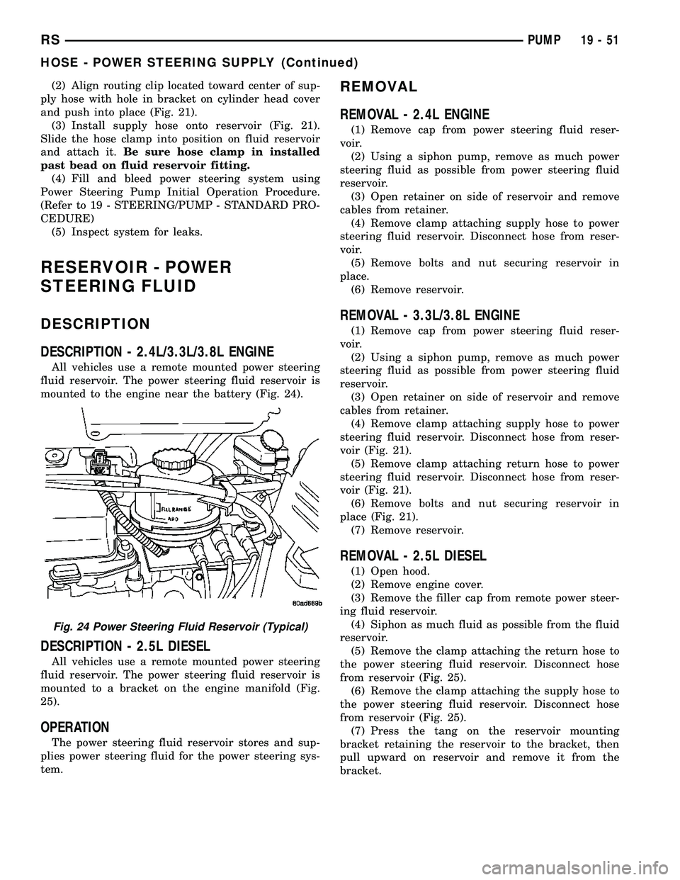
DESCRIPTION - 2.4L/3.3L/3.8L ENGINE
All vehicles use a remote mounted power steering
fluid reservoir. The power steering fluid reservoir is
mounted to the engine near the battery (Fig. 24).
DESCRIPTION - 2.5L DIESEL
All vehicles use a remote mounted power steering
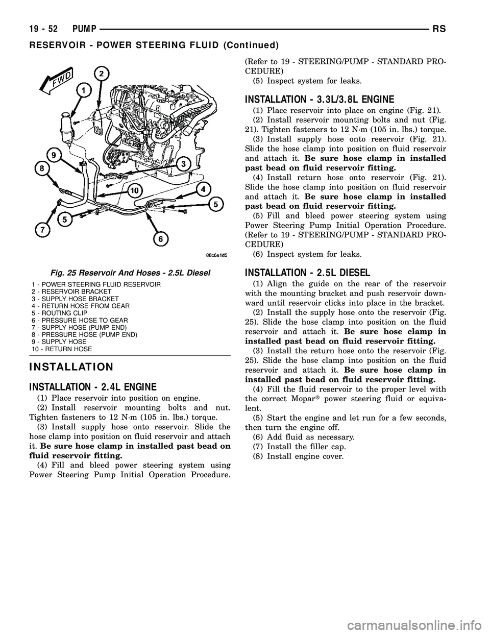
fluid reservoir. The power steering fluid reservoir is
mounted to a bracket on the engine manifold (Fig.
25).
OPERATION
The power steering fluid reservoir stores and sup-
plies power steering fluid for the power steering sys-
tem.
REMOVAL
REMOVAL - 2.4L ENGINE
(1) Remove cap from power steering fluid reser-
voir.
(2) Using a siphon pump, remove as much power
steering fluid as possible from power steering fluid
reservoir.
(3) Open retainer on side of reservoir and remove
cables from retainer.
(4) Remove clamp attaching supply hose to power
steering fluid reservoir. Disconnect hose from reser-
voir.
(5) Remove bolts and nut securing reservoir in
place.
(6) Remove reservoir.
REMOVAL - 3.3L/3.8L ENGINE
(1) Remove cap from power steering fluid reser-
voir.
(2) Using a siphon pump, remove as much power
steering fluid as possible from power steering fluid
reservoir.
(3) Open retainer on side of reservoir and remove
cables from retainer.
(4) Remove clamp attaching supply hose to power
steering fluid reservoir. Disconnect hose from reser-
voir (Fig. 21).
(5) Remove clamp attaching return hose to power
steering fluid reservoir. Disconnect hose from reser-
voir (Fig. 21).
(6) Remove bolts and nut securing reservoir in
place (Fig. 21).
(7) Remove reservoir.
REMOVAL - 2.5L DIESEL
(1) Open hood.
(2) Remove engine cover.
(3) Remove the filler cap from remote power steer-
ing fluid reservoir.
(4) Siphon as much fluid as possible from the fluid
reservoir.
(5) Remove the clamp attaching the return hose to
the power steering fluid reservoir. Disconnect hose
from reservoir (Fig. 25).
(6) Remove the clamp attaching the supply hose to
the power steering fluid reservoir. Disconnect hose
from reservoir (Fig. 25).
(7) Press the tang on the reservoir mounting
bracket retaining the reservoir to the bracket, then
pull upward on reservoir and remove it from the
bracket.
Fig. 24 Power Steering Fluid Reservoir (Typical)
RSPUMP19-51
HOSE - POWER STEERING SUPPLY (Continued)
Page 1597 of 2585
INSTALLATION
INSTALLATION - 2.4L ENGINE
(1) Place reservoir into position on engine.
(2) Install reservoir mounting bolts and nut.
Tighten fasteners to 12 N´m (105 in. lbs.) torque.
(3) Install supply hose onto reservoir. Slide the
hose clamp into position on fluid reservoir and attach
it.Be sure hose clamp in installed past bead on
fluid reservoir fitting.
(4) Fill and bleed power steering system using
Power Steering Pump Initial Operation Procedure.(Refer to 19 - STEERING/PUMP - STANDARD PRO-
CEDURE)
(5) Inspect system for leaks.
INSTALLATION - 3.3L/3.8L ENGINE
(1) Place reservoir into place on engine (Fig. 21).
(2) Install reservoir mounting bolts and nut (Fig.
21). Tighten fasteners to 12 N´m (105 in. lbs.) torque.
(3) Install supply hose onto reservoir (Fig. 21).
Slide the hose clamp into position on fluid reservoir
and attach it.Be sure hose clamp in installed
past bead on fluid reservoir fitting.
(4) Install return hose onto reservoir (Fig. 21).
Slide the hose clamp into position on fluid reservoir
and attach it.Be sure hose clamp in installed
past bead on fluid reservoir fitting.
(5) Fill and bleed power steering system using
Power Steering Pump Initial Operation Procedure.
(Refer to 19 - STEERING/PUMP - STANDARD PRO-
CEDURE)
(6) Inspect system for leaks.
INSTALLATION - 2.5L DIESEL
(1) Align the guide on the rear of the reservoir
with the mounting bracket and push reservoir down-
ward until reservoir clicks into place in the bracket.
(2) Install the supply hose onto the reservoir (Fig.
25). Slide the hose clamp into position on the fluid
reservoir and attach it.Be sure hose clamp in
installed past bead on fluid reservoir fitting.
(3) Install the return hose onto the reservoir (Fig.
25). Slide the hose clamp into position on the fluid
reservoir and attach it.Be sure hose clamp in
installed past bead on fluid reservoir fitting.
(4) Fill the fluid reservoir to the proper level with
the correct Mopartpower steering fluid or equiva-
lent.
(5) Start the engine and let run for a few seconds,
then turn the engine off.
(6) Add fluid as necessary.
(7) Install the filler cap.
(8) Install engine cover.
Fig. 25 Reservoir And Hoses - 2.5L Diesel
1 - POWER STEERING FLUID RESERVOIR
2 - RESERVOIR BRACKET
3 - SUPPLY HOSE BRACKET
4 - RETURN HOSE FROM GEAR
5 - ROUTING CLIP
6 - PRESSURE HOSE TO GEAR
7 - SUPPLY HOSE (PUMP END)
8 - PRESSURE HOSE (PUMP END)
9 - SUPPLY HOSE
10 - RETURN HOSE
19 - 52 PUMPRS
RESERVOIR - POWER STEERING FLUID (Continued)
Page 1601 of 2585
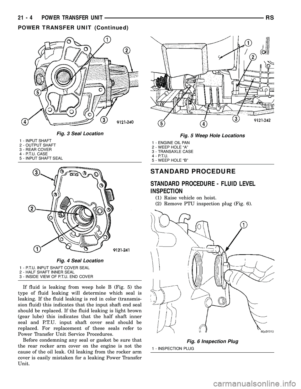
If fluid is leaking from weep hole B (Fig. 5) the
type of fluid leaking will determine which seal is
leaking. If the fluid leaking is red in color (transmis-
sion fluid) this indicates that the input shaft end seal
should be replaced. If the fluid leaking is light brown
(gear lube) this indicates that the half shaft inner
seal and P.T.U. input shaft cover seal should be
replaced. For replacement of these seals refer to
Power Transfer Unit Service Procedures.
Before condemning any seal or gasket be sure that
the rear rocker arm cover on the engine is not the
cause of the oil leak. Oil leaking from the rocker arm
cover is easily mistaken for a leaking Power Transfer
Unit.
STANDARD PROCEDURE
STANDARD PROCEDURE - FLUID LEVEL
INSPECTION
(1) Raise vehicle on hoist.
(2) Remove PTU inspection plug (Fig. 6).
Fig. 3 Seal Location
1 - INPUT SHAFT
2 - OUTPUT SHAFT
3 - REAR COVER
4 - P.T.U. CASE
5 - INPUT SHAFT SEAL
Fig. 4 Seal Location
1 - P.T.U. INPUT SHAFT COVER SEAL
2 - HALF SHAFT INNER SEAL
3 - INSIDE VIEW OF P.T.U. END COVER
Fig. 5 Weep Hole Locations
1 - ENGINE OIL PAN
2 - WEEP HOLE ªAº
3 - TRANSAXLE CASE
4 - P.T.U.
5 - WEEP HOLE ªBº
Fig. 6 Inspection Plug
1 - INSPECTION PLUG
21 - 4 POWER TRANSFER UNITRS
POWER TRANSFER UNIT (Continued)
Page 1620 of 2585
The NV T850 transaxle is available with the 2.4L
Gas and 2.5L Turbo Diesel engine options. Unique
gearing tailored to the performance characteristics of
each engine provides optimum driveability, gradabil-
ity, and acceleration. The gear ratios are as follows:
GEARRATIO (2.4L
Gas)RATIO (2.5L
TD)
1st 3.65 3.65
2nd 2.05 2.05
3rd 1.39 1.37
4th 1.03 0.97
5th 0.83 0.76
Reverse 3.47 3.47
Final Drive
Ratio3.77 3.77
Overall Top
Gear3.12 2.67
TRANSAXLE IDENTIFICATION
NOTE: Since transaxles use unique gear ratios for
each of the two engine applications, it is imperative
that the transaxle is properly identified, and the cor-
rect transaxle assembly number is used when
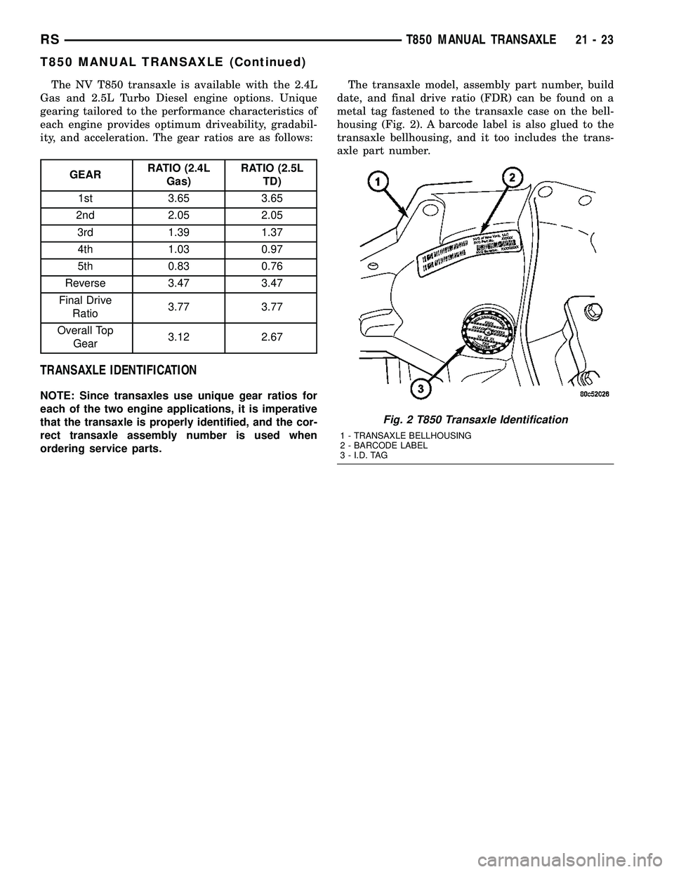
ordering service parts.The transaxle model, assembly part number, build
date, and final drive ratio (FDR) can be found on a
metal tag fastened to the transaxle case on the bell-
housing (Fig. 2). A barcode label is also glued to the
transaxle bellhousing, and it too includes the trans-
axle part number.
Fig. 2 T850 Transaxle Identification
1 - TRANSAXLE BELLHOUSING
2 - BARCODE LABEL
3 - I.D. TAG
RST850 MANUAL TRANSAXLE21-23
T850 MANUAL TRANSAXLE (Continued)
Page 1621 of 2585
OPERATION
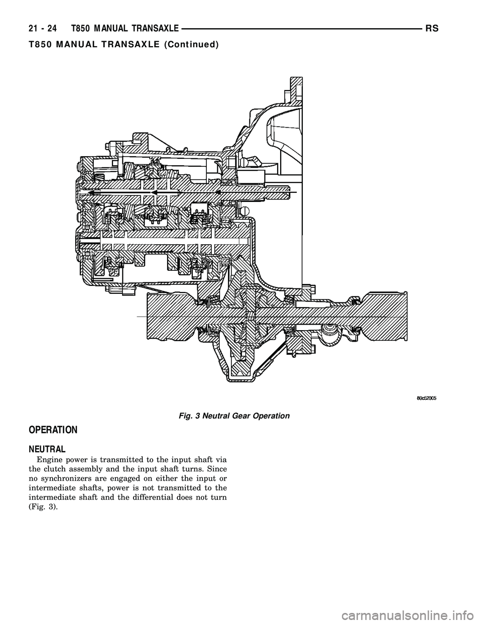
NEUTRAL
Engine power is transmitted to the input shaft via
the clutch assembly and the input shaft turns. Since
no synchronizers are engaged on either the input or
intermediate shafts, power is not transmitted to the
intermediate shaft and the differential does not turn
(Fig. 3).
Fig. 3 Neutral Gear Operation
21 - 24 T850 MANUAL TRANSAXLERS
T850 MANUAL TRANSAXLE (Continued)