2004 CHRYSLER VOYAGER tire pressure
[x] Cancel search: tire pressurePage 683 of 2585

message must be sent to the Powertrain Control
Module (PCM) within two seconds of ignition ON to
free the engine from immobilization.
The SKREEM contains a Radio Frequency (RF)
transceiver and a microprocessor. The SKREEM
retains in memory the ID numbers of any Sentry Key
that is programmed to it. The maximum number of
keys that may be programmed to each module is
eight (8). The SKREEM also communicates over the
Programmable Communication Interface (PCI) data
bus with the Powertrain Control Module (PCM), the
Body Control Module (BCM), the Mechanical Instru-
ment Cluster (MIC), and the DRB IIItscan tool. The
SKREEM transmits and receives RF signals through
a tuned antenna enclosed within a molded plastic
ring formation that is integral to the SKREEM hous-
ing. When the SKREEM is properly installed on the
steering column, the antenna ring fits snugly around
the circumference of the ignition lock cylinder hous-
ing. If this ring is not mounted properly, communica-
tion problems may arise in the form of transponder-
related faults.
For added system security, each SKREEM is pro-
grammed with a unique9Secret Key9code. This code
is stored in memory and is sent over the PCI bus to
the PCM and to each key that is programmed to
work with the vehicle. The9Secret Key9code is there-
fore a common element found in all components of
the Sentry Key Immobilizer System (SKIS). In the
event that a SKREEM replacement is required, the
9Secret Key9code can be restored from the PCM by
following the SKIM replacement procedure found in
the DRB IIItscan tool. Proper completion of this
task will allow the existing ignition keys to be repro-
grammed. Therefore, new keys will NOT be needed.
In the event that the original9Secret Key9code can
not be recovered, new ignition keys will be required.
The DRB IIItscan tool will alert the technician if
key replacement is necessary. Another security code,
called a PIN, is used to gain secured access to the
SKREEM for service. The SKREEM also stores in its
memory the Vehicle Identification Number (VIN),
which it learns through a bus message from the
assembly plant tester. The SKIS scrambles the infor-
mation that is communicated between its components
in order to reduce the possibility of unauthorized
SKREEM access and/or disabling.
REMOTE KEYLESS ENTRY (RKE)
The RKE transmitter uses radio frequency signals
to communicate with the SKREEM. The SKREEM is
on the PCI bus. When the operator presses a button
on the transmitter, it sends a specific request to the
SKREEM. In turn the SKREEM sends the appropri-
ate request over the PCI Bus to the:²Body Control Module (BCM) to control the door
lock and unlock functions, the liftgate lock and
unlock functions, the arming and disarming of the
Vehicle Theft Security System (VTSS) (if equipped),
and the activation of illuminated entry.
²Integrated Power Module (IPM) to activate the
park lamps, the headlamps, and the horn for horn
chirp. If requested, the BCM sends a request over
the PCI Bus to the:
TIRE PRESSURE MONITORING (TPM)
If equipped with the Tire Pressure Monitoring
(TPM) System, each of the vehicles four wheels will
have a valve stem with a pressure sensor and radio
transmitter built in. Signals from the tire pressure
sensor/transmitter are received and interpreted by
the SKREEM.
A sensor/transmitter in a mounted wheel will
broadcast its detected pressure once per minute
when the vehicle is moving faster than 15 mph (24
km/h). Each sensor/transmitter's broadcast is
uniquely coded so that the SKREEM can determine
the location.
OPERATION
SENTRY KEY IMMOBILIZER
The Sentry Key Remote Entry Module (SKREEM)
receives an encrypted Radio Frequency (RF) signal
from the transponder key. The SKREEM then
decrypts the signal and broadcasts the requested
remote commands to the appropriate modules in the
vehicle over the Programmable Communication
Interface (PCI) data bus. A valid transponder key ID
must be incorporated into the RF signal in order for
the SKREEM to pass the message on to the appro-
priate modules.
Automatic transponder key synchronization is done
by the SKREEM if a valid transponder key is
inserted into the ignition cylinder, and the ignition is
turned ON. This provides a maximum operation win-
dow for RKE functions.
Each Sentry Key Remote Entry System (SKREES)
consists of a SKREEM and a transponder key. Each
system has a secret key code unique to that system.
The secret key is electronically coded in the
SKREEM and in all programmed transponder keys.
It is used for immobilization and RKE functions for
data security. In addition, each transponder key will
have a unique identification.
When the ignition switch is moved to the RUN
position, the SKREEM transmits an Radio Frequency
(RF) signal to the transponder in the ignition key.
The SKREEM then waits for a response RF signal
from the transponder in the key. If the response
received identifies the key as valid, the SKREEM
8Q - 4 VEHICLE THEFT SECURITYRS
SENTRY KEY REMOTE ENTRY MODULE (Continued)
Page 684 of 2585

sends a9valid key9message to the Powertrain Con-
trol Module (PCM) over the Programmable Commu-
nication Interface (PCI) data bus. If the response
received identifies the key as invalid or no response
is received from the transponder in the ignition key,
the SKREEM sends an9invalid key9message to the
PCM. The PCM will enable or disable engine opera-
tion based upon the status of the SKREEM mes-
sages. It is important to note that the default
condition in the PCM is9invalid key.9Therefore, if no
response is received by the PCM, the engine will be
immobilized after two (2) seconds of running.
The SKREEM also sends indicator light status
messages to the Mechanical Instrument Cluster
(MIC) to operate the light. This is the method used to
turn the light ON solid or to flash it after the indi-
cator light test is complete to signify a fault in the
SKREES. If the light comes ON and stays ON solid
after the indicator light test, this signifies that the
SKREEM has detected a system malfunction and/or
that the SKREES has become inoperative. If the
SKREEM detects an invalid keyORa key-related
fault exists, the indicator light will flash following
the indicator light test. The SKREEM may also
request an audible chime if the customer key pro-
gramming feature is available and the procedure is
being utilized (Refer to 8 - ELECTRICAL/VEHICLE
THEFT SECURITY/TRANSPONDER KEY - STAN-
DARD PROCEDURE).
REMOTE KEYLESS ENTRY (RKE)
After pressing the lock button on the RKE trans-
mitter, all of the door locks will lock, the illuminated
entry will turn off (providing all doors are closed),
and the VTSS (if equipped) will arm. After pressing
the unlock button, on the RKE transmitter, one time,
the driver door lock will unlock, the illuminated
entry will turn on the courtesy lamps, and the VTSS
(if equipped) will disarm. After pressing the unlock
button a second time, the remaining door locks will
unlock. The Electronic Vehicle Information Center
(EVIC) or the DRBIIItscan tool can reprogram this
feature to unlock all of the door locks with one press
of the unlock button. If the vehicle is equipped with
the memory system, the memory message will iden-
tify which transmitter (1 or 2) sent the signal.
The SKREEM is capable of retaining up to 8 indi-
vidual access codes (8 transmitters). If the PRNDL is
in any position except park, the SKREEM will dis-
able the RKE. The 4 button transmitter uses
1-CR2032 battery. The minimum battery life is
approximately 4.7 years based on 20 transmissions a
day at 84ÉF (25ÉC). Use the DRBIIItscan tool or the
Miller Tool 9001 RF Detector to test the RKE trans-
mitter. Use the DRBIIItor the customer program-
ming method to program the RKE system. However,the SKREEM will only allow RKE programming
when the ignition is in the ON position, the PRNDL
is in park position, and the VTSS (if equipped) is dis-
armed.
TIRE PRESSURE MONITORING (TPM)
The SKREEM monitors the signals from the tire
pressure sensor/transmitters and determines if any
tire has gone below the low pressure threshold LOW
TIRE PRESSURE THRESHOLDS table.
LOW TIRE PRESSURE THRESHOLDS
SYSTEM STATUS
INDICATORTIRE PRESSURE
ON 193 kPa (28 PSI)
OFF 227 kPa (33 PSI)
CRITICAL AND NON-CRITICAL SYSTEM ALERTS
CRITICAL:A critical alert will be triggered when
a tire pressure has gone below a set threshold pres-
sure. The SKREEM will display ªX TIRE(S) LOW
PRESSUREº. ªXº will be the number of tires report-
ing low pressure. The message will display for the
duration of the current ignition cycle or until an
EVIC button is pressed. If the display is removed
without correcting the condition, it will reappear 300
seconds to warn the driver of the low pressure condi-
tion.
NON-CRITICAL:A non-critical alert will be trig-
gered when no signal is received from a sensor/trans-
mitter. The EVIC display in the cluster will display
ªSERVICE TIRE SYSTEM SOON.º
DIAGNOSIS AND TESTING - SENTRY KEY
REMOTE ENTRY MODULE
For proper diagnosis and testing of the Sentry Key
Remote Entry Module (SKREEM), use a DRBllltand
refer to the proper Body Diagnostic Procedures infor-
mation.
REMOVAL
(1) Disconnect and isolate the battery negative
cable.
(2) Remove the Steering Column Opening Cover
(Refer to 23 - BODY/INSTRUMENT PANEL/STEER-
ING COLUMN OPENING COVER - REMOVAL).
(3) Remove the steering column upper and lower
shrouds (Refer to 19 - STEERING/COLUMN/UPPER
SHROUD - REMOVAL) and (Refer to 19 - STEER-
ING/COLUMN/LOWER SHROUD - REMOVAL).
(4) Disengage the steering column wire harness
from the Sentry Key Remote Entry Module
(SKREEM).
(5) Remove the one screws securing the SKREEM
to the steering column.
RSVEHICLE THEFT SECURITY8Q-5
SENTRY KEY REMOTE ENTRY MODULE (Continued)
Page 1305 of 2585
CONDITION POSSIBLE CAUSES CORRECTION
OIL CONSUMPTION OR SPARK
PLUGS FOULED1. PCV system malfunction. 1. Check system and repair as
necessary. (Refer to 25 -
EMISSIONS CONTROL/
EVAPORATIVE EMISSIONS/PCV
VALVE - DIAGNOSIS AND
TESTING)
2. Worn, scuffed or broken rings. 2. Hone cylinder bores. Install new
rings.
3. Carbon in oil ring slots. 3. Install new rings.
4. Rings fitted too tightly in grooves. 4. Remove rings and check
grooves. If groove is not proper
width, replace piston.
5. Worn valve guide(s). 5. Replace cylinder head assembly.
6. Valve stem seal(s) worn or
damaged.6. Replace seal(s).
DIAGNOSIS AND TESTING - ENGINE OIL LEAK
INSPECTION
Begin with a thorough visual inspection of the
engine, particularly at the area of the suspected leak.
If an oil leak source is not readily identifiable, the
following steps should be followed:
(1) Do not clean or degrease the engine at this
time because some solvents may cause rubber to
swell, temporarily stopping the leak.
(2) Add an oil soluble dye (use as recommended by
manufacturer). Start the engine and let idle for
approximately 15 minutes. Check the oil dipstick to
make sure the dye is thoroughly mixed as indicated
with a bright yellow color under a black light.
(3) Using a black light, inspect the entire engine
for fluorescent dye, particularly at the suspected area
of oil leak. If the oil leak is found and identified,
repair as necessary.
(4) If dye is not observed, drive the vehicle at var-
ious speeds for approximately 24 km (15 miles), and
repeat inspection.
(5)If the oil leak source is not positively
identified at this time, proceed with the air leak
detection test method as follows:
²Disconnect the fresh air hose (make-up air) at
the cylinder head cover and plug or cap the nipple on
the cover.
²Remove the PCV valve hose from the cylinder
head cover. Cap or plug the PCV valve nipple on the
cover.
²Attach an air hose with pressure gauge and reg-
ulator to the dipstick tube.
CAUTION: Do not subject the engine assembly to
more than 20.6 kpa (3 PSI) of test pressure.²Gradually apply air pressure from 1 psi to 2.5
psi maximum while applying soapy water at the sus-
pected source. Adjust the regulator to the suitable
test pressure that provides the best bubbles which
will pinpoint the leak source. If the oil leak is
detected and identified, repair per service manual
procedures.
²If the leakage occurs at the crankshaft rear oil
seal area, refer to the section, Inspection for Rear
Seal Area Leak.
(6) If no leaks are detected, turn off the air supply.
Remove the air hose, all plugs, and caps. Install the
PCV valve and fresh air hose (make-up air). Proceed
to next step.
(7) Clean the oil off the suspect oil leak area using
a suitable solvent. Drive the vehicle at various
speeds approximately 24 km (15 miles). Inspect the
engine for signs of an oil leak by using a black light.
NOTE: If oil leakage is observed at the dipstick tube
to block location; remove the tube, clean and reseal
using MoparTStud & Bearing Mount (press fit tube
applications only), and for O-ring style tubes,
remove tube and replace the O-ring seal.
INSPECTION FOR REAR SEAL AREA LEAKS
Since it is sometimes difficult to determine the
source of an oil leak in the rear seal area of the
engine, a more involved inspection is necessary. The
following steps should be followed to help pinpoint
the source of the leak.
If the leakage occurs at the crankshaft rear oil seal
area:
(1) Disconnect the battery.
(2) Raise the vehicle.
9 - 8 ENGINE 2.4LRS
ENGINE 2.4L (Continued)
Page 1309 of 2585
NOTE: Multi-Layer Steel (MLS) head gaskets require
a scratch free sealing surface.
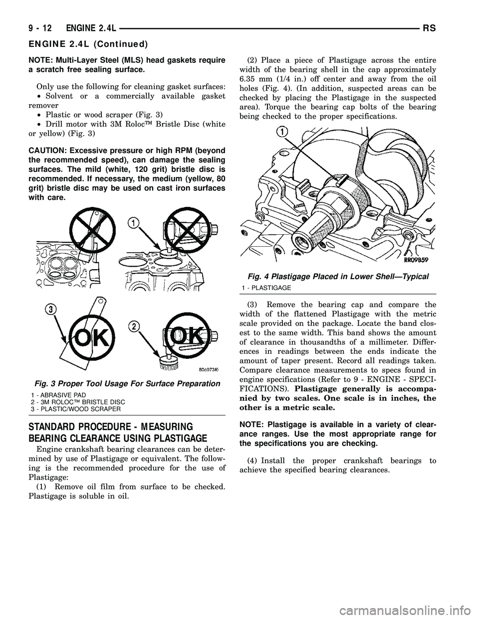
Only use the following for cleaning gasket surfaces:
²Solvent or a commercially available gasket
remover
²Plastic or wood scraper (Fig. 3)
²Drill motor with 3M RolocŸ Bristle Disc (white
or yellow) (Fig. 3)
CAUTION: Excessive pressure or high RPM (beyond
the recommended speed), can damage the sealing
surfaces. The mild (white, 120 grit) bristle disc is
recommended. If necessary, the medium (yellow, 80
grit) bristle disc may be used on cast iron surfaces
with care.
STANDARD PROCEDURE - MEASURING
BEARING CLEARANCE USING PLASTIGAGE
Engine crankshaft bearing clearances can be deter-
mined by use of Plastigage or equivalent. The follow-
ing is the recommended procedure for the use of
Plastigage:
(1) Remove oil film from surface to be checked.
Plastigage is soluble in oil.(2) Place a piece of Plastigage across the entire
width of the bearing shell in the cap approximately
6.35 mm (1/4 in.) off center and away from the oil
holes (Fig. 4). (In addition, suspected areas can be
checked by placing the Plastigage in the suspected
area). Torque the bearing cap bolts of the bearing
being checked to the proper specifications.
(3) Remove the bearing cap and compare the
width of the flattened Plastigage with the metric
scale provided on the package. Locate the band clos-
est to the same width. This band shows the amount
of clearance in thousandths of a millimeter. Differ-
ences in readings between the ends indicate the
amount of taper present. Record all readings taken.
Compare clearance measurements to specs found in
engine specifications (Refer to 9 - ENGINE - SPECI-
FICATIONS).Plastigage generally is accompa-
nied by two scales. One scale is in inches, the
other is a metric scale.
NOTE: Plastigage is available in a variety of clear-
ance ranges. Use the most appropriate range for
the specifications you are checking.
(4) Install the proper crankshaft bearings to
achieve the specified bearing clearances.
Fig. 3 Proper Tool Usage For Surface Preparation
1 - ABRASIVE PAD
2 - 3M ROLOCŸ BRISTLE DISC
3 - PLASTIC/WOOD SCRAPER
Fig. 4 Plastigage Placed in Lower ShellÐTypical
1 - PLASTIGAGE
9 - 12 ENGINE 2.4LRS
ENGINE 2.4L (Continued)
Page 1310 of 2585
REMOVAL - ENGINE ASSEMBLY
(1) Perform fuel pressure release procedure (Refer
to 14 - FUEL SYSTEM/FUEL DELIVERY - STAN-
DARD PROCEDURE)
(2) Disconnect battery negative cable.
(3) Remove air cleaner housing and inlet tube.
(4) Disconnect the fuel line from fuel rail. (Refer to
14 - FUEL SYSTEM/FUEL DELIVERY/FUEL LINES
- STANDARD PROCEDURE)
(5) Disconnect all vacuum hoses.
(6) Drain cooling system. (Refer to 7 - COOLING -
STANDARD PROCEDURE)
(7) Remove radiator fans. (Refer to 7 - COOLING/
ENGINE/RADIATOR FAN - REMOVAL)
(8) Remove radiator upper and lower hoses.
NOTE: When the transaxle cooler lines are removed
from the rolled-groove type fittings at the transaxle,
damage to the inner wall of the hose will occur. To
prevent prevent potential leakage, the cooler hoses
must be cut off flush at the transaxle fitting, and a
service cooler hose splice kit must be installed
upon reassembly.(9) Using a blade or suitable hose cutter, cut trans-
axle oil cooler lines off flush with fittings. Plug cooler
lines and fittings to prevent debris from entering
transaxle or cooler circuit. A service splice kit will be
installed upon reassembly.
(10) Disconnect transmission shift linkage and
electrical connectors.
(11) Disconnect throttle body linkage.
(12) Disconnect engine wiring harness.
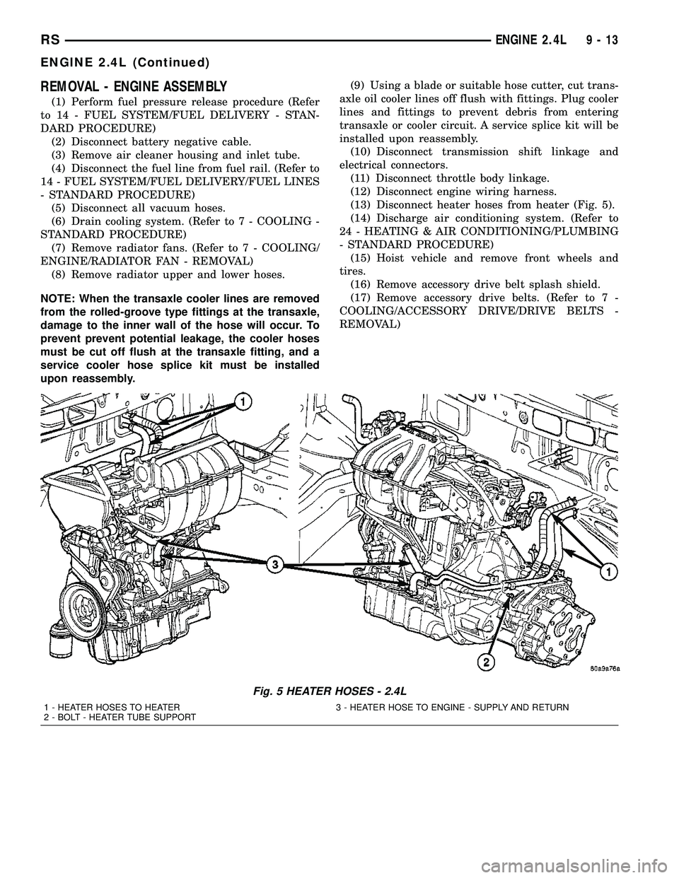
(13) Disconnect heater hoses from heater (Fig. 5).
(14) Discharge air conditioning system. (Refer to
24 - HEATING & AIR CONDITIONING/PLUMBING
- STANDARD PROCEDURE)
(15) Hoist vehicle and remove front wheels and
tires.
(16) Remove accessory drive belt splash shield.
(17) Remove accessory drive belts. (Refer to 7 -
COOLING/ACCESSORY DRIVE/DRIVE BELTS -
REMOVAL)
Fig. 5 HEATER HOSES - 2.4L
1 - HEATER HOSES TO HEATER 3 - HEATER HOSE TO ENGINE - SUPPLY AND RETURN
2 - BOLT - HEATER TUBE SUPPORT
RSENGINE 2.4L9-13
ENGINE 2.4L (Continued)
Page 1379 of 2585
CONDITION POSSIBLE CAUSES CORRECTION
OIL CONSUMPTION OR SPARK
PLUGS FOULED1. PCV system malfunction. 1. Check system and repair as
necessary. (Refer to 25 -
EMISSIONS CONTROL/
EVAPORATIVE EMISSIONS/PCV
VALVE - DIAGNOSIS AND
TESTING)
2. Worn, scuffed or broken rings. 2. Hone cylinder bores. Install new
rings.
3. Carbon in oil ring slots. 3. Install new rings.
4. Rings fitted too tightly in grooves. 4. Remove rings and check
grooves. If groove is not proper
width, replace piston.
5. Worn valve guide(s). 5. Replace cylinder head assembly.
6. Valve stem seal(s) worn or
damaged.6. Replace seal(s).
DIAGNOSIS AND TESTING - ENGINE OIL LEAK
INSPECTION
Begin with a thorough visual inspection of the
engine, particularly at the area of the suspected leak.
If an oil leak source is not readily identifiable, the
following steps should be followed:
(1) Do not clean or degrease the engine at this
time because some solvents may cause rubber to
swell, temporarily stopping the leak.
(2) Add an oil soluble dye (use as recommended by
manufacturer). Start the engine and let idle for
approximately 15 minutes. Check the oil dipstick to
make sure the dye is thoroughly mixed as indicated
with a bright yellow color under a black light.
(3) Using a black light, inspect the entire engine
for fluorescent dye, particularly at the suspected area
of oil leak. If the oil leak is found and identified,
repair as necessary.
(4) If dye is not observed, drive the vehicle at var-
ious speeds for approximately 24 km (15 miles), and
repeat inspection.
(5)If the oil leak source is not positively
identified at this time, proceed with the air leak
detection test method as follows:
²Disconnect the fresh air hose (make-up air) at
the cylinder head cover and plug or cap the nipple on
the cover.
²Remove the PCV valve hose from the cylinder
head cover. Cap or plug the PCV valve nipple on the
cover.
²Attach an air hose with pressure gauge and reg-
ulator to the dipstick tube.
CAUTION: Do not subject the engine assembly to
more than 20.6 kpa (3 PSI) of test pressure.²Gradually apply air pressure from 1 psi to 2.5
psi maximum while applying soapy water at the sus-
pected source. Adjust the regulator to the suitable
test pressure that provides the best bubbles which
will pinpoint the leak source. If the oil leak is
detected and identified, repair per service manual
procedures.
²If the leakage occurs at the crankshaft rear oil
seal area, refer to the section, Inspection for Rear
Seal Area Leak.
(6) If no leaks are detected, turn off the air supply.
Remove the air hose, all plugs, and caps. Install the
PCV valve and fresh air hose (make-up air). Proceed
to next step.
(7) Clean the oil off the suspect oil leak area using
a suitable solvent. Drive the vehicle at various
speeds approximately 24 km (15 miles). Inspect the
engine for signs of an oil leak by using a black light.
NOTE: If oil leakage is observed at the dipstick tube
to block location; remove the tube, clean and reseal
using MoparTStud & Bearing Mount (press fit tube
applications only), and for O-ring style tubes,
remove tube and replace the O-ring seal.
INSPECTION FOR REAR SEAL AREA LEAKS
Since it is sometimes difficult to determine the
source of an oil leak in the rear seal area of the
engine, a more involved inspection is necessary. The
following steps should be followed to help pinpoint
the source of the leak.
If the leakage occurs at the crankshaft rear oil seal
area:
(1) Disconnect the battery.
(2) Raise the vehicle.
9 - 82 ENGINE 3.3/3.8LRS
ENGINE 3.3/3.8L (Continued)
Page 1381 of 2585
Calibrate the tester according to the manufactur-
er's instructions. The shop air source for testing
should maintain 483 kPa (70 psi) minimum, 1,379
kPa (200 psi) maximum, with 552 kPa (80 psi) rec-
ommended.
Perform the test procedures on each cylinder
according to the tester manufacturer's instructions.
While testing, listen for pressurized air escaping
through the throttle body, tailpipe and oil filler cap
opening. Check for bubbles in the coolant.
All gauge pressure indications should be equal,
with no more than 25% leakage per cylinder.
FOR EXAMPLE:At 552 kPa (80 psi) input pres-
sure, a minimum of 414 kPa (60 psi) should be main-
tained in the cylinder.
STANDARD PROCEDURE
STANDARD PROCEDURE - MEASURING
BEARING CLEARANCE USING PLASTIGAGE
Engine crankshaft bearing clearances can be deter-
mined by use of Plastigage or equivalent. The follow-
ing is the recommended procedure for the use of
Plastigage:
(1) Remove oil film from surface to be checked.
Plastigage is soluble in oil.
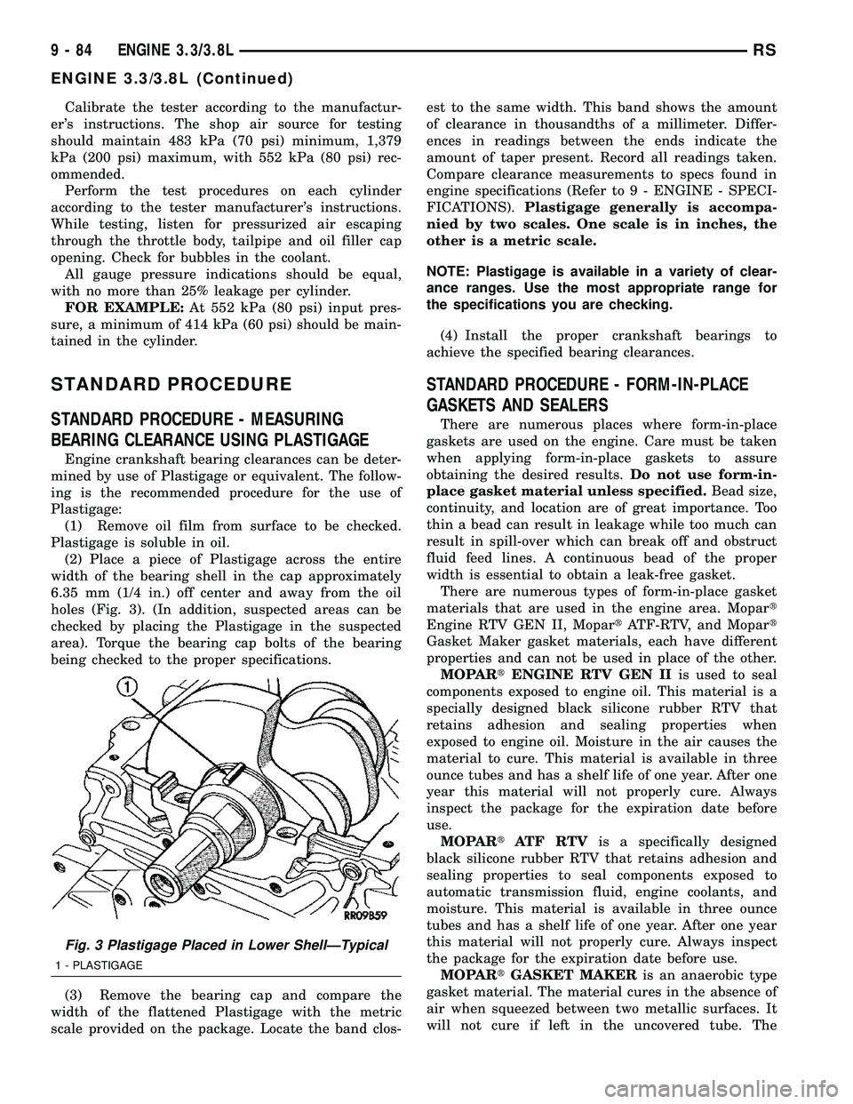
(2) Place a piece of Plastigage across the entire
width of the bearing shell in the cap approximately
6.35 mm (1/4 in.) off center and away from the oil
holes (Fig. 3). (In addition, suspected areas can be
checked by placing the Plastigage in the suspected
area). Torque the bearing cap bolts of the bearing
being checked to the proper specifications.
(3) Remove the bearing cap and compare the
width of the flattened Plastigage with the metric
scale provided on the package. Locate the band clos-est to the same width. This band shows the amount
of clearance in thousandths of a millimeter. Differ-
ences in readings between the ends indicate the
amount of taper present. Record all readings taken.
Compare clearance measurements to specs found in
engine specifications (Refer to 9 - ENGINE - SPECI-
FICATIONS).Plastigage generally is accompa-
nied by two scales. One scale is in inches, the
other is a metric scale.
NOTE: Plastigage is available in a variety of clear-
ance ranges. Use the most appropriate range for
the specifications you are checking.
(4) Install the proper crankshaft bearings to
achieve the specified bearing clearances.
STANDARD PROCEDURE - FORM-IN-PLACE
GASKETS AND SEALERS
There are numerous places where form-in-place
gaskets are used on the engine. Care must be taken
when applying form-in-place gaskets to assure
obtaining the desired results.Do not use form-in-
place gasket material unless specified.Bead size,
continuity, and location are of great importance. Too
thin a bead can result in leakage while too much can
result in spill-over which can break off and obstruct
fluid feed lines. A continuous bead of the proper
width is essential to obtain a leak-free gasket.
There are numerous types of form-in-place gasket
materials that are used in the engine area. Mopart
Engine RTV GEN II, MopartATF-RTV, and Mopart
Gasket Maker gasket materials, each have different
properties and can not be used in place of the other.
MOPARtENGINE RTV GEN IIis used to seal
components exposed to engine oil. This material is a
specially designed black silicone rubber RTV that
retains adhesion and sealing properties when
exposed to engine oil. Moisture in the air causes the
material to cure. This material is available in three
ounce tubes and has a shelf life of one year. After one
year this material will not properly cure. Always
inspect the package for the expiration date before
use.
MOPARtATF RTVis a specifically designed
black silicone rubber RTV that retains adhesion and
sealing properties to seal components exposed to
automatic transmission fluid, engine coolants, and
moisture. This material is available in three ounce
tubes and has a shelf life of one year. After one year
this material will not properly cure. Always inspect
the package for the expiration date before use.
MOPARtGASKET MAKERis an anaerobic type
gasket material. The material cures in the absence of
air when squeezed between two metallic surfaces. It
will not cure if left in the uncovered tube. The
Fig. 3 Plastigage Placed in Lower ShellÐTypical
1 - PLASTIGAGE
9 - 84 ENGINE 3.3/3.8LRS
ENGINE 3.3/3.8L (Continued)
Page 1550 of 2585

CONDITION POSSIBLE CAUSES CORRECTION
SQUEAK OR RUBBING
SOUND1. Steering column shroud rubbing. 1. Realign shrouds as necessary.
2. Steering column shaft rubbing. 2. Move or realign item rubbing shaft.
3. Clockspring noisy. 3. Remove clockspring. Reinstall wheel.
If noise is gone, replace clockspring.
4. Seal lubrication inadequate. 4. Lube seal (if external).
5. Steering gear internally noisy. 5. Replace steering gear (if no other
cause can be found).
SCRUBBING OR
KNOCKING NOISE.1. Incorrect tire or wheel size. 1. Replace incorrect size tire or wheel
with size used as original equipment.
2. Interference between steering
gear and other vehicle components.2. Check for bent or misaligned
components and correct as necessary.
3. Steering gear internal stops worn
excessively allowing tires to be
steered excessively far.3. Replace steering gear.
NOTE: * There is some noise in all power steering
systems. One of the most common is a hissing
sound evident when turning the steering wheel
when at a standstill or when parking and the steer-
ing wheel is at the end of its travel. Hiss is a very
high frequency noise similar to that experienced
while slowly closing a water tap. The noise is
present in every valve and results when high veloc-
ity fluid passes valve orifice edges. There is no
relationship between this noise and the perfor-
mance of the steering system.NOTE: ** A light clunk may be felt or heard during
steering wheel reversal while vehicle is stationary.
This results from internal steering gear rack move-
ment at the bushings and in no way affects the per-
formance of the steering system. This movement
may be felt in the steering components during
steering wheel reversal.
NOTE: *** Power steering pump growl/moan/groan
results from the development of high pressure fluid
flow. Normally this noise level should not be high
enough to be objectionable.
STEERING WHEEL FEEL
CONDITION POSSIBLE CAUSES CORRECTION
STEERING WHEEL/
COLUMN CLICKING,
CLUNKING OR RATTLING.1. Loose steering coupling pinch
bolt.1. Replace pinch bolt and torque to
specifications.
2. Steering column bearings. 2. Replace steering column.
3. Excessive intermediate shaft
coupling free-play.3. Replace intermediate shaft.
STEERING WHEEL HAS
FORE AND AFT
LOOSENESS.1. Steering wheel retaining nut not
properly tightened and torqued.1. Tighten the steering wheel retaining nut
to its specified torque.
2. Steering column lower bearing
spring retainer slipped on steering
column shaft.2. Replace steering column.
3. Loose steering column to
instrument panel fasteners.3. Tighten fasteners to specified torque.
RSSTEERING19-5
STEERING (Continued)