2004 CHRYSLER VOYAGER oil level
[x] Cancel search: oil levelPage 1313 of 2585
INSTALLATION - ENGINE ASSEMBLY
(1) Position engine and transmission assembly
under vehicle and slowly lower the vehicle over the
engine and transmission.
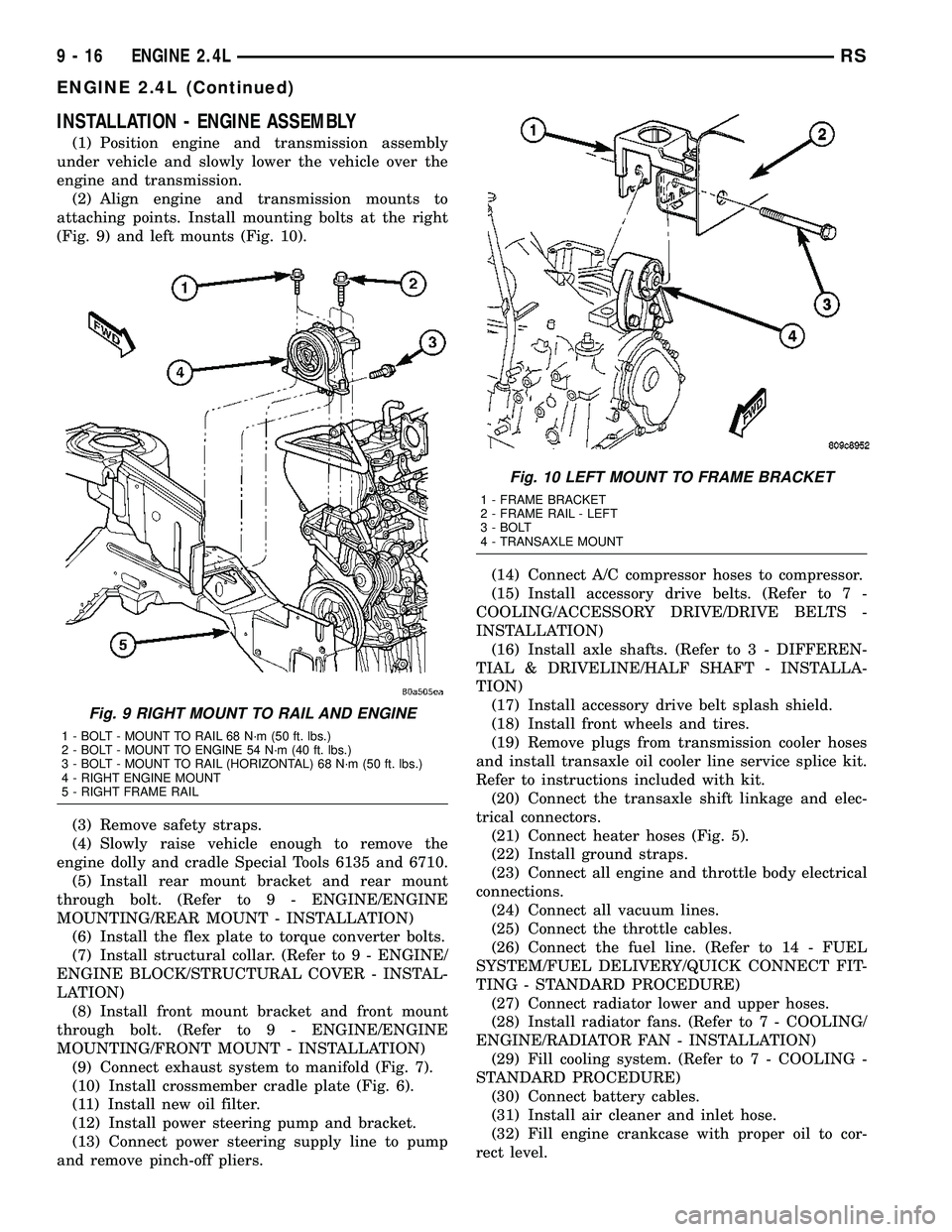
(2) Align engine and transmission mounts to
attaching points. Install mounting bolts at the right
(Fig. 9) and left mounts (Fig. 10).
(3) Remove safety straps.
(4) Slowly raise vehicle enough to remove the
engine dolly and cradle Special Tools 6135 and 6710.
(5) Install rear mount bracket and rear mount
through bolt. (Refer to 9 - ENGINE/ENGINE
MOUNTING/REAR MOUNT - INSTALLATION)
(6) Install the flex plate to torque converter bolts.
(7) Install structural collar. (Refer to 9 - ENGINE/
ENGINE BLOCK/STRUCTURAL COVER - INSTAL-
LATION)
(8) Install front mount bracket and front mount
through bolt. (Refer to 9 - ENGINE/ENGINE
MOUNTING/FRONT MOUNT - INSTALLATION)
(9) Connect exhaust system to manifold (Fig. 7).
(10) Install crossmember cradle plate (Fig. 6).
(11) Install new oil filter.
(12) Install power steering pump and bracket.
(13) Connect power steering supply line to pump
and remove pinch-off pliers.(14) Connect A/C compressor hoses to compressor.
(15) Install accessory drive belts. (Refer to 7 -
COOLING/ACCESSORY DRIVE/DRIVE BELTS -
INSTALLATION)
(16) Install axle shafts. (Refer to 3 - DIFFEREN-
TIAL & DRIVELINE/HALF SHAFT - INSTALLA-
TION)
(17) Install accessory drive belt splash shield.
(18) Install front wheels and tires.
(19) Remove plugs from transmission cooler hoses
and install transaxle oil cooler line service splice kit.
Refer to instructions included with kit.
(20) Connect the transaxle shift linkage and elec-
trical connectors.
(21) Connect heater hoses (Fig. 5).
(22) Install ground straps.
(23) Connect all engine and throttle body electrical
connections.
(24) Connect all vacuum lines.
(25) Connect the throttle cables.
(26) Connect the fuel line. (Refer to 14 - FUEL
SYSTEM/FUEL DELIVERY/QUICK CONNECT FIT-
TING - STANDARD PROCEDURE)
(27) Connect radiator lower and upper hoses.
(28) Install radiator fans. (Refer to 7 - COOLING/
ENGINE/RADIATOR FAN - INSTALLATION)
(29) Fill cooling system. (Refer to 7 - COOLING -
STANDARD PROCEDURE)
(30) Connect battery cables.
(31) Install air cleaner and inlet hose.
(32) Fill engine crankcase with proper oil to cor-
rect level.
Fig. 9 RIGHT MOUNT TO RAIL AND ENGINE
1 - BOLT - MOUNT TO RAIL 68 N´m (50 ft. lbs.)
2 - BOLT - MOUNT TO ENGINE 54 N´m (40 ft. lbs.)
3 - BOLT - MOUNT TO RAIL (HORIZONTAL) 68 N´m (50 ft. lbs.)
4 - RIGHT ENGINE MOUNT
5 - RIGHT FRAME RAIL
Fig. 10 LEFT MOUNT TO FRAME BRACKET
1 - FRAME BRACKET
2 - FRAME RAIL - LEFT
3 - BOLT
4 - TRANSAXLE MOUNT
9 - 16 ENGINE 2.4LRS
ENGINE 2.4L (Continued)
Page 1331 of 2585
HYDRAULIC LASH
ADJUSTERS
DIAGNOSIS AND TESTING - HYDRAULIC LASH
ADJUSTER NOISE DIAGNOSIS
A tappet-like noise may be produced from several
items. Check the following items.
(1) Engine oil level too high or too low. This may
cause aerated oil to enter the adjusters and cause
them to be spongy.
(2) Insufficient running time after rebuilding cylin-
der head. Low speed running up to 1 hour may be
required.
(3) During this time, turn engine off and let set for
a few minutes before restarting. Repeat this several
times after engine has reached normal operating
temperature.
(4) Low oil pressure.
(5) The oil restrictor (integral to the head gasket)
in the vertical oil passage to the cylinder head is
plugged with debris.
(6) Air ingested into oil due to broken or cracked
oil pump pick up.
(7) Worn valve guides.
(8) Rocker arm ears contacting valve spring
retainer.
(9) Rocker arm loose, adjuster stuck or at maxi-
mum extension and still leaves lash in the system.
(10) Faulty lash adjuster.
²Check lash adjusters for sponginess while
installed in cylinder head. Depress part of rocker
arm over adjuster. Normal adjusters should feel very
firm. Spongy adjusters can be bottomed out easily.
²Remove suspected lash adjusters, and replace as
necessary.
REMOVAL
NOTE: This procedure is for in-vehicle service with
camshafts installed.
(1) Remove cylinder head cover. (Refer to 9 -
ENGINE/CYLINDER HEAD/CYLINDER HEAD
COVER(S) - REMOVAL)
(2) Remove rocker arm. (Refer to 9 - ENGINE/
CYLINDER HEAD/ROCKER ARMS - REMOVAL)
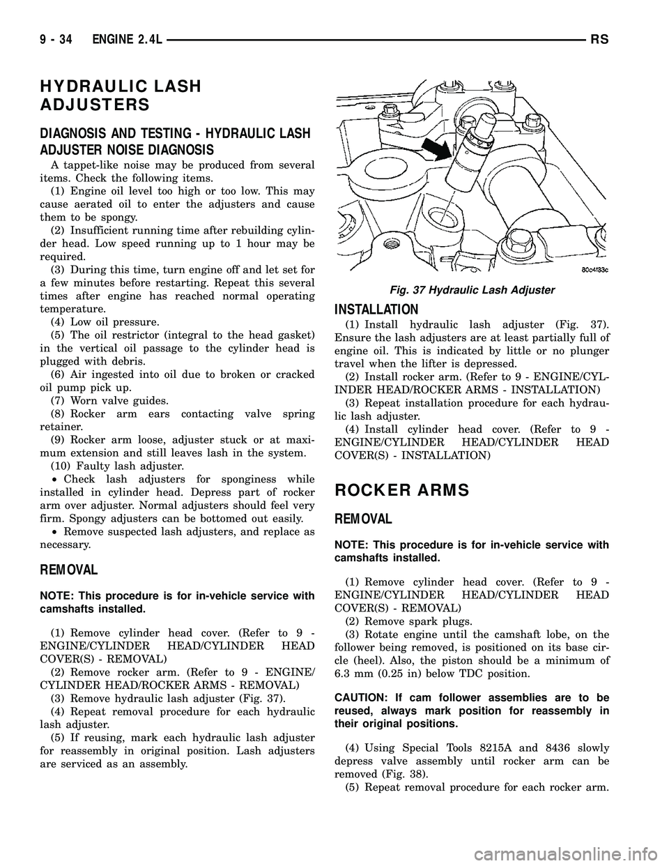
(3) Remove hydraulic lash adjuster (Fig. 37).
(4) Repeat removal procedure for each hydraulic
lash adjuster.
(5) If reusing, mark each hydraulic lash adjuster
for reassembly in original position. Lash adjusters
are serviced as an assembly.
INSTALLATION
(1) Install hydraulic lash adjuster (Fig. 37).
Ensure the lash adjusters are at least partially full of
engine oil. This is indicated by little or no plunger
travel when the lifter is depressed.
(2) Install rocker arm. (Refer to 9 - ENGINE/CYL-
INDER HEAD/ROCKER ARMS - INSTALLATION)
(3) Repeat installation procedure for each hydrau-
lic lash adjuster.
(4) Install cylinder head cover. (Refer to 9 -
ENGINE/CYLINDER HEAD/CYLINDER HEAD
COVER(S) - INSTALLATION)
ROCKER ARMS
REMOVAL
NOTE: This procedure is for in-vehicle service with
camshafts installed.
(1) Remove cylinder head cover. (Refer to 9 -
ENGINE/CYLINDER HEAD/CYLINDER HEAD
COVER(S) - REMOVAL)
(2) Remove spark plugs.
(3) Rotate engine until the camshaft lobe, on the
follower being removed, is positioned on its base cir-
cle (heel). Also, the piston should be a minimum of
6.3 mm (0.25 in) below TDC position.
CAUTION: If cam follower assemblies are to be
reused, always mark position for reassembly in
their original positions.
(4) Using Special Tools 8215A and 8436 slowly
depress valve assembly until rocker arm can be
removed (Fig. 38).
(5) Repeat removal procedure for each rocker arm.
Fig. 37 Hydraulic Lash Adjuster
9 - 34 ENGINE 2.4LRS
Page 1333 of 2585
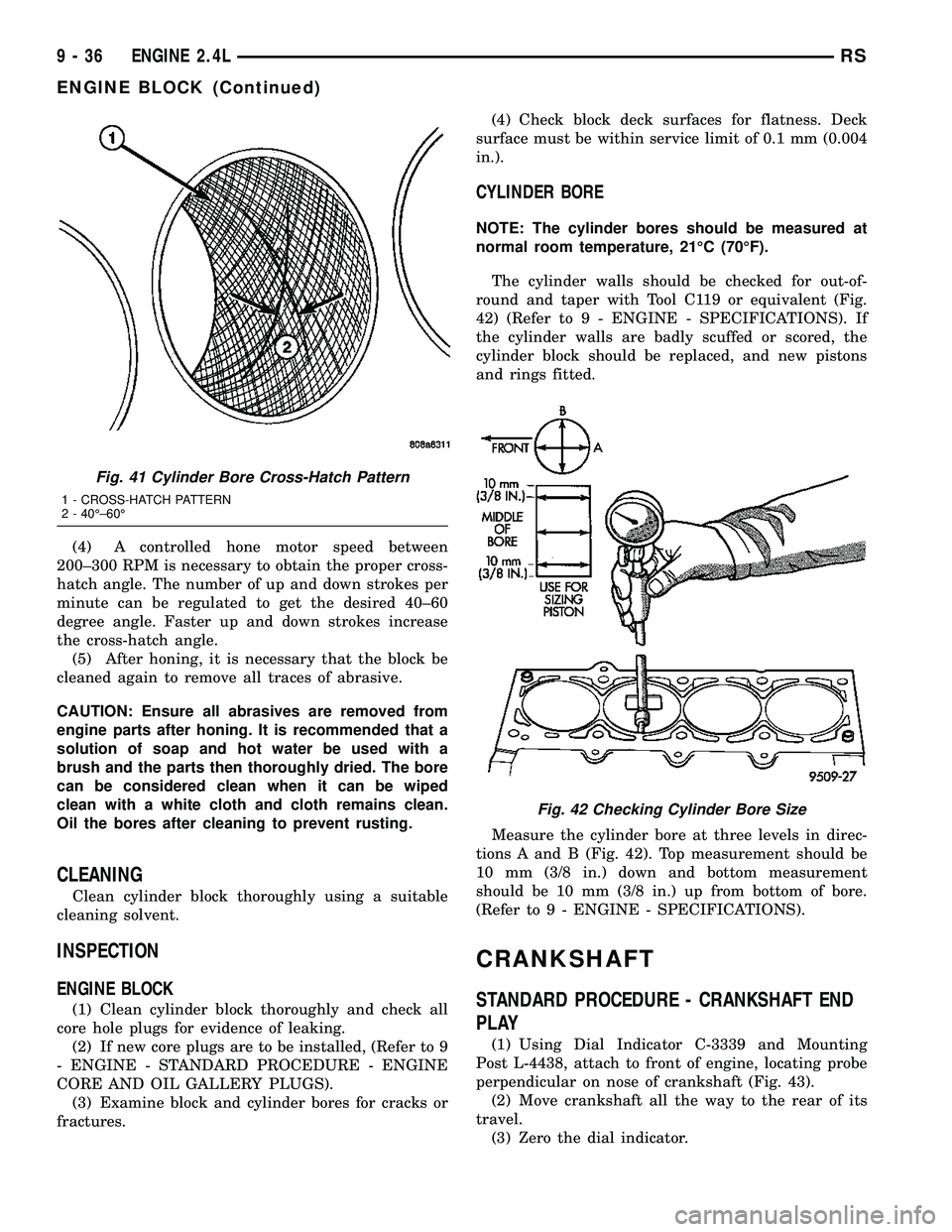
(4) A controlled hone motor speed between
200±300 RPM is necessary to obtain the proper cross-
hatch angle. The number of up and down strokes per
minute can be regulated to get the desired 40±60
degree angle. Faster up and down strokes increase
the cross-hatch angle.
(5) After honing, it is necessary that the block be
cleaned again to remove all traces of abrasive.
CAUTION: Ensure all abrasives are removed from
engine parts after honing. It is recommended that a
solution of soap and hot water be used with a
brush and the parts then thoroughly dried. The bore
can be considered clean when it can be wiped
clean with a white cloth and cloth remains clean.
Oil the bores after cleaning to prevent rusting.
CLEANING
Clean cylinder block thoroughly using a suitable
cleaning solvent.
INSPECTION
ENGINE BLOCK
(1) Clean cylinder block thoroughly and check all
core hole plugs for evidence of leaking.
(2) If new core plugs are to be installed, (Refer to 9
- ENGINE - STANDARD PROCEDURE - ENGINE
CORE AND OIL GALLERY PLUGS).
(3) Examine block and cylinder bores for cracks or
fractures.(4) Check block deck surfaces for flatness. Deck
surface must be within service limit of 0.1 mm (0.004
in.).
CYLINDER BORE
NOTE: The cylinder bores should be measured at
normal room temperature, 21ÉC (70ÉF).
The cylinder walls should be checked for out-of-
round and taper with Tool C119 or equivalent (Fig.
42) (Refer to 9 - ENGINE - SPECIFICATIONS). If
the cylinder walls are badly scuffed or scored, the
cylinder block should be replaced, and new pistons
and rings fitted.
Measure the cylinder bore at three levels in direc-
tions A and B (Fig. 42). Top measurement should be
10 mm (3/8 in.) down and bottom measurement
should be 10 mm (3/8 in.) up from bottom of bore.
(Refer to 9 - ENGINE - SPECIFICATIONS).
CRANKSHAFT
STANDARD PROCEDURE - CRANKSHAFT END
PLAY
(1) Using Dial Indicator C-3339 and Mounting
Post L-4438, attach to front of engine, locating probe
perpendicular on nose of crankshaft (Fig. 43).
(2) Move crankshaft all the way to the rear of its
travel.
(3) Zero the dial indicator.
Fig. 41 Cylinder Bore Cross-Hatch Pattern
1 - CROSS-HATCH PATTERN
2 - 40ɱ60É
Fig. 42 Checking Cylinder Bore Size
9 - 36 ENGINE 2.4LRS
ENGINE BLOCK (Continued)
Page 1350 of 2585
OIL
STANDARD PROCEDURE
ENGINE OIL LEVEL CHECK
The best time to check engine oil level is after it
has sat overnight, or if the engine has been running,
allow the engine to be shut off for at least 5 minutes
before checking oil level.
Checking the oil while the vehicle is on level
ground will improve the accuracy of the oil level
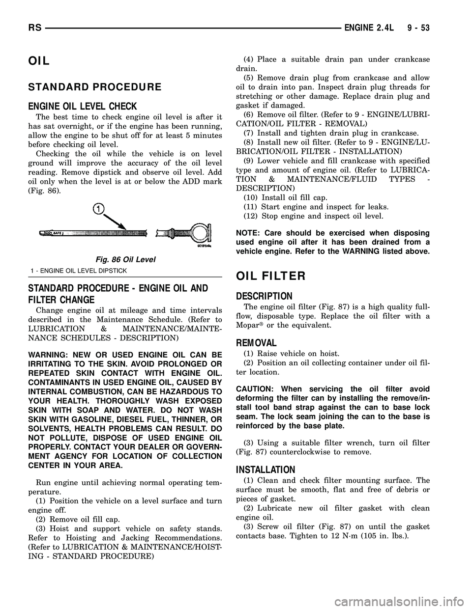
reading. Remove dipstick and observe oil level. Add
oil only when the level is at or below the ADD mark
(Fig. 86).
STANDARD PROCEDURE - ENGINE OIL AND
FILTER CHANGE
Change engine oil at mileage and time intervals
described in the Maintenance Schedule. (Refer to
LUBRICATION & MAINTENANCE/MAINTE-
NANCE SCHEDULES - DESCRIPTION)
WARNING: NEW OR USED ENGINE OIL CAN BE
IRRITATING TO THE SKIN. AVOID PROLONGED OR
REPEATED SKIN CONTACT WITH ENGINE OIL.
CONTAMINANTS IN USED ENGINE OIL, CAUSED BY
INTERNAL COMBUSTION, CAN BE HAZARDOUS TO
YOUR HEALTH. THOROUGHLY WASH EXPOSED
SKIN WITH SOAP AND WATER. DO NOT WASH
SKIN WITH GASOLINE, DIESEL FUEL, THINNER, OR
SOLVENTS, HEALTH PROBLEMS CAN RESULT. DO
NOT POLLUTE, DISPOSE OF USED ENGINE OIL
PROPERLY. CONTACT YOUR DEALER OR GOVERN-
MENT AGENCY FOR LOCATION OF COLLECTION
CENTER IN YOUR AREA.
Run engine until achieving normal operating tem-
perature.
(1) Position the vehicle on a level surface and turn
engine off.
(2) Remove oil fill cap.
(3) Hoist and support vehicle on safety stands.
Refer to Hoisting and Jacking Recommendations.
(Refer to LUBRICATION & MAINTENANCE/HOIST-
ING - STANDARD PROCEDURE)(4) Place a suitable drain pan under crankcase
drain.
(5) Remove drain plug from crankcase and allow
oil to drain into pan. Inspect drain plug threads for
stretching or other damage. Replace drain plug and
gasket if damaged.
(6) Remove oil filter. (Refer to 9 - ENGINE/LUBRI-
CATION/OIL FILTER - REMOVAL)
(7) Install and tighten drain plug in crankcase.
(8) Install new oil filter. (Refer to 9 - ENGINE/LU-
BRICATION/OIL FILTER - INSTALLATION)
(9) Lower vehicle and fill crankcase with specified
type and amount of engine oil. (Refer to LUBRICA-
TION & MAINTENANCE/FLUID TYPES -
DESCRIPTION)
(10) Install oil fill cap.
(11) Start engine and inspect for leaks.
(12) Stop engine and inspect oil level.
NOTE: Care should be exercised when disposing
used engine oil after it has been drained from a
vehicle engine. Refer to the WARNING listed above.
OIL FILTER
DESCRIPTION
The engine oil filter (Fig. 87) is a high quality full-
flow, disposable type. Replace the oil filter with a
Mopartor the equivalent.
REMOVAL
(1) Raise vehicle on hoist.
(2) Position an oil collecting container under oil fil-
ter location.
CAUTION: When servicing the oil filter avoid
deforming the filter can by installing the remove/in-
stall tool band strap against the can to base lock
seam. The lock seam joining the can to the base is
reinforced by the base plate.
(3) Using a suitable filter wrench, turn oil filter
(Fig. 87) counterclockwise to remove.
INSTALLATION
(1) Clean and check filter mounting surface. The
surface must be smooth, flat and free of debris or
pieces of gasket.
(2) Lubricate new oil filter gasket with clean
engine oil.
(3) Screw oil filter (Fig. 87) on until the gasket
contacts base. Tighten to 12 N´m (105 in. lbs.).
Fig. 86 Oil Level
1 - ENGINE OIL LEVEL DIPSTICK
RSENGINE 2.4L9-53
Page 1351 of 2585
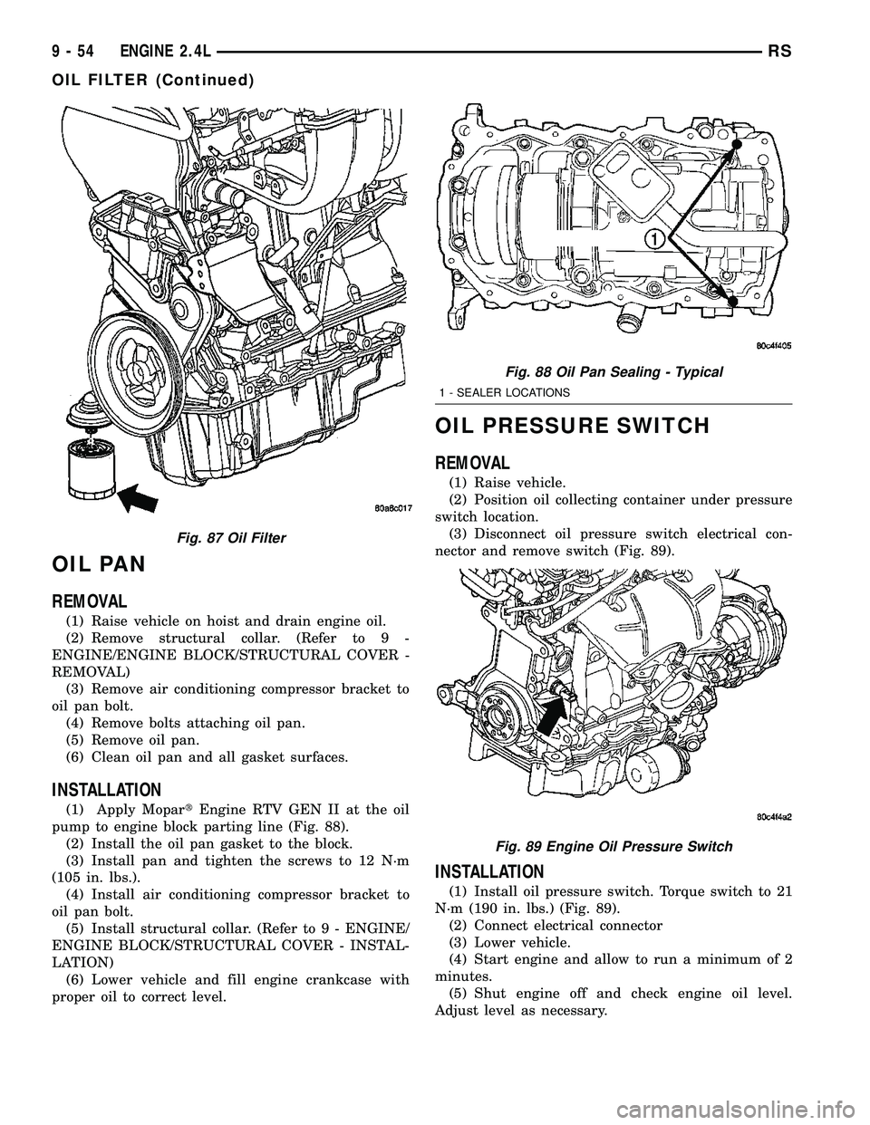
OIL PAN
REMOVAL
(1) Raise vehicle on hoist and drain engine oil.
(2) Remove structural collar. (Refer to 9 -
ENGINE/ENGINE BLOCK/STRUCTURAL COVER -
REMOVAL)
(3) Remove air conditioning compressor bracket to
oil pan bolt.
(4) Remove bolts attaching oil pan.
(5) Remove oil pan.
(6) Clean oil pan and all gasket surfaces.
INSTALLATION
(1) Apply MopartEngine RTV GEN II at the oil
pump to engine block parting line (Fig. 88).
(2) Install the oil pan gasket to the block.
(3) Install pan and tighten the screws to 12 N´m
(105 in. lbs.).
(4) Install air conditioning compressor bracket to
oil pan bolt.
(5) Install structural collar. (Refer to 9 - ENGINE/
ENGINE BLOCK/STRUCTURAL COVER - INSTAL-
LATION)
(6) Lower vehicle and fill engine crankcase with
proper oil to correct level.
OIL PRESSURE SWITCH
REMOVAL
(1) Raise vehicle.
(2) Position oil collecting container under pressure
switch location.
(3) Disconnect oil pressure switch electrical con-
nector and remove switch (Fig. 89).
INSTALLATION
(1) Install oil pressure switch. Torque switch to 21
N´m (190 in. lbs.) (Fig. 89).
(2) Connect electrical connector
(3) Lower vehicle.
(4) Start engine and allow to run a minimum of 2
minutes.
(5) Shut engine off and check engine oil level.
Adjust level as necessary.
Fig. 87 Oil Filter
Fig. 88 Oil Pan Sealing - Typical
1 - SEALER LOCATIONS
Fig. 89 Engine Oil Pressure Switch
9 - 54 ENGINE 2.4LRS
OIL FILTER (Continued)
Page 1370 of 2585
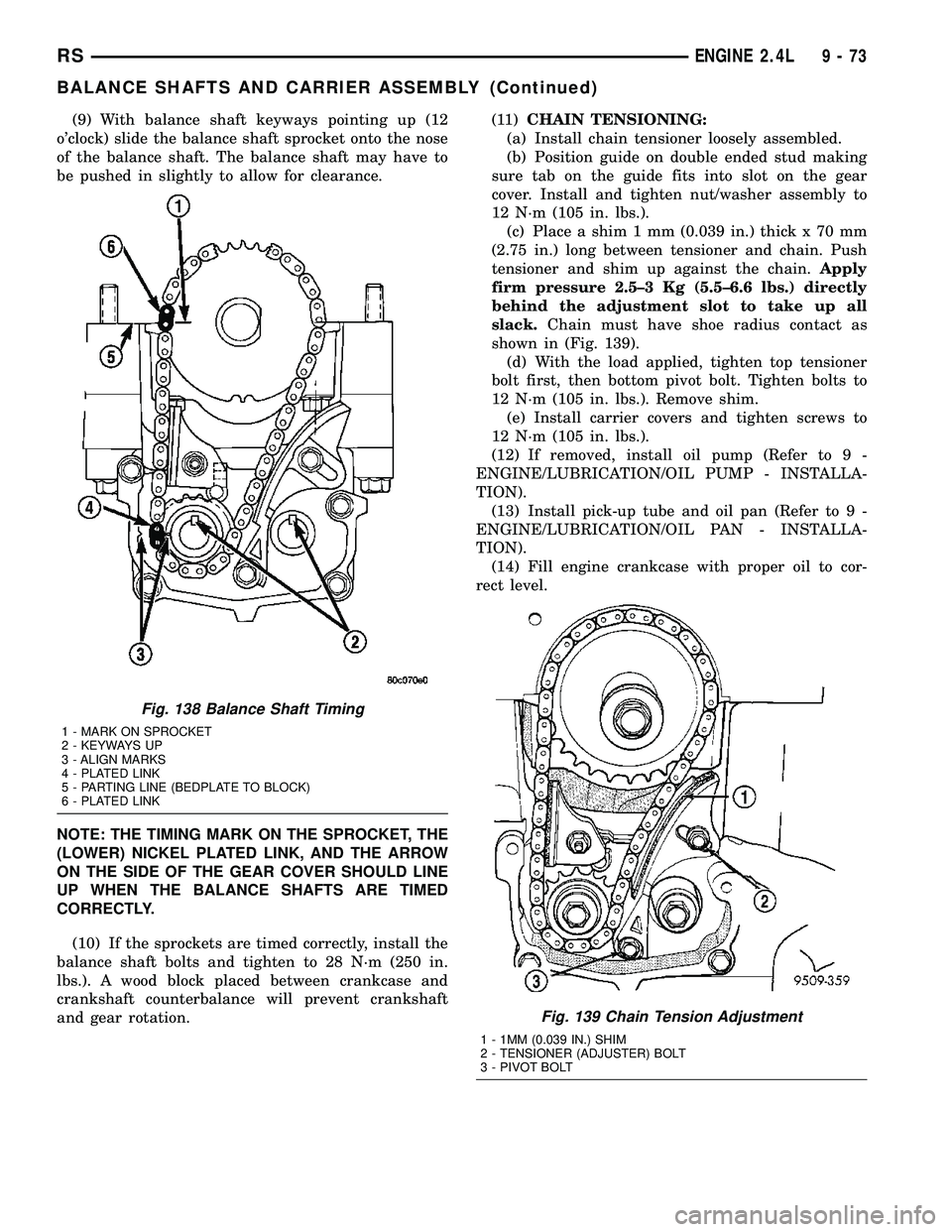
(9) With balance shaft keyways pointing up (12
o'clock) slide the balance shaft sprocket onto the nose
of the balance shaft. The balance shaft may have to
be pushed in slightly to allow for clearance.
NOTE: THE TIMING MARK ON THE SPROCKET, THE
(LOWER) NICKEL PLATED LINK, AND THE ARROW
ON THE SIDE OF THE GEAR COVER SHOULD LINE
UP WHEN THE BALANCE SHAFTS ARE TIMED
CORRECTLY.
(10) If the sprockets are timed correctly, install the
balance shaft bolts and tighten to 28 N´m (250 in.
lbs.). A wood block placed between crankcase and
crankshaft counterbalance will prevent crankshaft
and gear rotation.(11)CHAIN TENSIONING:
(a) Install chain tensioner loosely assembled.
(b) Position guide on double ended stud making
sure tab on the guide fits into slot on the gear
cover. Install and tighten nut/washer assembly to
12 N´m (105 in. lbs.).
(c) Place a shim 1 mm (0.039 in.) thick x 70 mm
(2.75 in.) long between tensioner and chain. Push
tensioner and shim up against the chain.Apply
firm pressure 2.5±3 Kg (5.5±6.6 lbs.) directly
behind the adjustment slot to take up all
slack.Chain must have shoe radius contact as
shown in (Fig. 139).
(d) With the load applied, tighten top tensioner
bolt first, then bottom pivot bolt. Tighten bolts to
12 N´m (105 in. lbs.). Remove shim.
(e) Install carrier covers and tighten screws to
12 N´m (105 in. lbs.).
(12) If removed, install oil pump (Refer to 9 -
ENGINE/LUBRICATION/OIL PUMP - INSTALLA-
TION).
(13) Install pick-up tube and oil pan (Refer to 9 -
ENGINE/LUBRICATION/OIL PAN - INSTALLA-
TION).
(14) Fill engine crankcase with proper oil to cor-
rect level.
Fig. 138 Balance Shaft Timing
1 - MARK ON SPROCKET
2 - KEYWAYS UP
3 - ALIGN MARKS
4 - PLATED LINK
5 - PARTING LINE (BEDPLATE TO BLOCK)
6 - PLATED LINK
Fig. 139 Chain Tension Adjustment
1 - 1MM (0.039 IN.) SHIM
2 - TENSIONER (ADJUSTER) BOLT
3 - PIVOT BOLT
RSENGINE 2.4L9-73
BALANCE SHAFTS AND CARRIER ASSEMBLY (Continued)
Page 1372 of 2585
INSPECTION..........................112
HYDRAULIC LIFTERS (CAM IN BLOCK)
DESCRIPTION........................113
DIAGNOSIS AND TESTING - HYDRAULIC
LIFTERS...........................113
REMOVAL............................114
INSTALLATION........................114
CAMSHAFT & BEARINGS (IN BLOCK)
DESCRIPTION........................115
OPERATION..........................115
REMOVAL............................115
INSPECTION..........................115
INSTALLATION........................115
PISTON & CONNECTING ROD
DESCRIPTION........................116
STANDARD PROCEDURE
STANDARD PROCEDURE - FITTING
CONNECTING RODS..................116
STANDARD PROCEDURE - FITTING
PISTONS...........................117
REMOVAL............................117
INSTALLATION........................118
CONNECTING ROD BEARINGS
STANDARD PROCEDURE - MEASURING
CONNECTING ROD BEARING CLEARANCE
. . 120
PISTON RINGS
STANDARD PROCEDURE - PISTON RING
FITTING............................121
REMOVAL............................121
INSTALLATION........................121
CRANKSHAFT MAIN BEARINGS
STANDARD PROCEDURE - MAIN BEARING
FITTING............................123
REMOVAL - CRANKSHAFT MAIN BEARINGS . 124
INSTALLATION - CRANKSHAFT MAIN
BEARINGS..........................124
CRANKSHAFT
DESCRIPTION
DESCRIPTION - 3.3L..................125
DESCRIPTION - 3.8L..................125
STANDARD PROCEDURE - MEASURING
CRANKSHAFT END PLAY..............125
REMOVAL............................125
INSTALLATION........................126
CRANKSHAFT OIL SEAL - FRONT
REMOVAL............................127
INSTALLATION........................127
CRANKSHAFT OIL SEAL - REAR
REMOVAL............................128
INSTALLATION........................129
CRANKSHAFT REAR OIL SEAL RETAINER
REMOVAL............................129
INSTALLATION........................129
VIBRATION DAMPER
REMOVAL............................130
INSTALLATION........................130FLEX PLATE
REMOVAL............................131
INSTALLATION........................131
ENGINE MOUNTING
DESCRIPTION........................131
FRONT MOUNT
REMOVAL............................131
INSTALLATION........................131
LEFT MOUNT
REMOVAL............................133
INSTALLATION........................133
REAR MOUNT
REMOVAL............................133
INSTALLATION........................134
RIGHT MOUNT
REMOVAL............................135
INSTALLATION........................135
LUBRICATION
DESCRIPTION........................136
OPERATION..........................136
DIAGNOSIS AND TESTING - ENGINE OIL
PRESSURE.........................136
OIL
STANDARD PROCEDURE
STANDARD PROCEDURE - ENGINE OIL
AND FILTER CHANGE.................137
STANDARD PROCEDURE - ENGINE OIL
LEVEL CHECK.......................137
OIL COOLER & LINES
DESCRIPTION........................138
OPERATION..........................138
REMOVAL............................138
INSTALLATION........................138
OIL FILTER
REMOVAL............................139
INSTALLATION........................139
OIL FILTER ADAPTER
REMOVAL............................139
INSTALLATION........................139
OIL PAN
REMOVAL............................140
CLEANING...........................140
INSPECTION.........................140
INSTALLATION........................140
OIL PRESSURE RELIEF VALVE
REMOVAL............................141
INSTALLATION........................141
OIL PRESSURE SWITCH
DESCRIPTION........................141
OPERATION..........................141
REMOVAL............................141
INSTALLATION........................141
OIL PUMP
DESCRIPTION........................142
REMOVAL............................142
DISASSEMBLY........................142
CLEANING...........................142
RSENGINE 3.3/3.8L9-75
Page 1377 of 2585
DIAGNOSIS AND TESTING - ENGINE DIAGNOSIS - MECHANICAL
CONDITION POSSIBLE CAUSES CORRECTION
NOISY VALVES 1. High or low oil level in
crankcase.1. Check and correct engine oil
level.
2. Thin or diluted oil. 2. Change oil to correct viscosity.
3. Thick oil 3. (a) Change engine oil and filter.
(b) Run engine to operating
temperature.
(c) Change engine oil and filter
again.
4. Low oil pressure. 4. Check and correct engine oil
pressure problem.
5. Dirt in hydraulic lifters/lash
adjusters.5. Replace hydraulic lifters/lash
adjusters.
6. Worn rocker arms. 6. Inspect oil supply to rocker arms.
7. Worn hydraulic lifters/lash
adjusters.7. Replace hydraulic lifters/lash
adjusters.
8. Worn valve guides. 8. Replace cylinder head assembly.
9. Excessive runout of valve seats
on valve faces.9. Grind valve seats and valves.
CONNECTING ROD NOISE 1. Insufficient oil supply. 1. Check engine oil level.
2. Low oil pressure. 2. Check engine oil level. Inspect oil
pump relief valve and spring.
3. Thin or diluted oil. 3. Change oil to correct viscosity.
4. Thick oil 4. (a) Change engine oil and filter.
(b) Run engine to operating
temperature.
(c) Change engine oil and filter
again.
5. Excessive bearing clearance. 5. Measure bearings for correct
clearance. Repair as necessary.
6. Connecting rod journal
out-of-round.6. Replace crankshaft or grind
surface.
7. Misaligned connecting rods. 7. Replace bent connecting rods.
9 - 80 ENGINE 3.3/3.8LRS
ENGINE 3.3/3.8L (Continued)