2004 CHRYSLER VOYAGER hood release
[x] Cancel search: hood releasePage 2176 of 2585

INSTRUMENT PANEL
ASSEMBLY
REMOVAL
(1) Disconnect and isolate the battery negative
cable.
(2) Remove the lower console:
(a) Remove six retaining screws.
(b) Pull rearward and disconnect the auxiliary
power outlet.
(c) Remove lower console from vehicle.
(3) Remove the bolts attaching the lower supports
to the instrument panel frame (Fig. 3).
(4) Remove the bolts attaching the lower supports
to the floor pan.
(5) Disconnect the wire connectors from the Pas-
senger Airbag.
(6) Remove the two screws to each right and left
cowl trim covers.
(7) Remove the both left and right side A-pillar
trim covers using a trim stick (special tool #C-4755)
or equivalent gently pry out on the trim covers and
remove.
(8) Remove the glove box:
(a) Push in on sides of glove box bin and lower
door.
(b) Pivot glove box downward and disengage
hinge hooks from instrument panel.
(c) Remove glove box from vehicle.
(9) Disconnect the antenna lead connector from
behind the glove box.
(10) Remove the four screws to the lower steering
column cover.
(11) Remove the eight screws to the steering col-
umn backing plate.
(12) Unclip the Data Link Connector (DLC) from
the steering column backing plate.
(13) Disconnect the left side wiring:
(a) Brake switch.
(b) Main bulkhead connector.
(c) Five harness connectors.
(d) Driver airbag connector.
(14) Remove the two screws to the hood release
handle.
(15) Remove five screws to steering column back-
ing plate and remove (Refer to 23 - BODY/INSTRU-
MENT PANEL/KNEE BLOCKER - REMOVAL).
(16) Remove the two steering column shroud
retaining screws. Separate the shrouds and remove
from vehicle.
(17) Remove the screws attaching the instrument
panel reinforcement and remove (Fig. 4).
(18) Disconnect the steering column wiring. There
are seven connectors and then unclip the harness
from the column.(19) Disconnect the Occupant Restraint Controller
(ORC) harness connector.
(20) Remove the four nuts retaining the steering
column to the dash panel steering column mounting
bracket and lower column to the floor (Fig. 5).
(21) Remove the four nuts attaching the instru-
ment panel to the brake pedal support bracket.
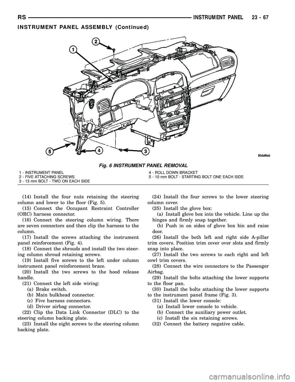
(22) Loosen the left side roll down bolt (Fig. 6).
(23) Remove the left side A-pillar retaining bolts.
There are two 13 mm bolts and one 10 mm bolt.
(24) If equipped with a mechanical transmission
range indicator:
(a) Remove the indicator cable loop.
(b) Remove the clip holding gear shift cable end
to the gear selector adapter.
(c) Pull the cable end from gear selector.
(d) Disconnect the clip for the indicator cable
and guide tube from the shift cable bracket and
move out of the way.
(25) Remove the instrument panel top cover. Using
a trim stick or equivalent, gently pry up on the front
edge of the top cover, pull rearward and remove from
vehicle.
(26) Disconnect the right side wire connectors from
the HVAC behind the glove box area and the two
antenna connectors behind the glove box hinge.
(27) Remove the right end cover by pulling out-
board.
(28) Remove the right side A-pillar retaining bolts.
There are two 13 mm bolts and one 10 mm bolt.
(29) Loosen the right side roll down bolt.
(30) Disconnect the two front window defroster
grid wire connectors. One on each side of vehicle.
(31) Remove both the left and right power mirrors:
(a) Using a trim stick or equivalent, gently pry
out on mirror trim cover.
(b) Open door and remove the three torx retain-
ing screws.
(c) Disconnect the wire connector and remove
mirror from the vehicle.
(32) Feed power mirror wire harness inboard
through the A-pillar.
(33) Remove the bolts attaching the instrument
panel frame to the dash panel below windshield
opening.
(34) With the help of an assistant remove the
instrument panel from vehicle. Lift the instrument
panel up off the HVAC so you won't damage the seal-
ing surface of the distribution duct.
If the instrument panel is being replaced, transfer
all parts to the new instrument panel assembly.
RSINSTRUMENT PANEL23-65
Page 2178 of 2585

(14) Install the four nuts retaining the steering
column and lower to the floor (Fig. 5).
(15) Connect the Occupant Restraint Controller
(ORC) harness connector.
(16) Connect the steering column wiring. There
are seven connectors and then clip the harness to the
column.
(17) Install the screws attaching the instrument
panel reinforcement (Fig. 4).
(18) Connect the shrouds and install the two steer-
ing column shroud retaining screws.
(19) Install five screws to the left under column
instrument panel reinforcement brace.
(20) Install the two screws to the hood release
handle.
(21) Connect the left side wiring:
(a) Brake switch.
(b) Main bulkhead connector.
(c) Five harness connectors.
(d) Driver airbag connector.
(22) Clip the Data Link Connector (DLC) to the
steering column backing plate.
(23) Install the eight screws to the steering column
backing plate.(24) Install the four screws to the lower steering
column cover.
(25) Install the glove box:
(a) Install glove box into the vehicle. Line up the
hinges and firmly snap together.
(b) Push in on sides of glove box bin and raise
door.
(26) Install the both left and right side A-pillar
trim covers. Position trim cover over slots and firmly
snap into place.
(27) Install the two screws to each right and left
cowl trim covers.
(28) Connect the wire connectors to the Passenger
Airbag.
(29) Install the bolts attaching the lower supports
to the floor pan.
(30) Install the bolts attaching the lower supports
to the instrument panel frame (Fig. 3).
(31) Install the lower console:
(a) Install lower console to vehicle.
(b) Connect the auxiliary power outlet.
(c) Install the six retaining screws.
(32) Connect the battery negative cable.
Fig. 6 INSTRUMENT PANEL REMOVAL
1 - INSTRUMENT PANEL
2 - FIVE ATTACHING SCREWS
3 - 13 mm BOLT - TWO ON EACH SIDE4 - ROLL DOWN BRACKET
5 - 10 mm BOLT - STARTING BOLT ONE EACH SIDE
RSINSTRUMENT PANEL23-67
INSTRUMENT PANEL ASSEMBLY (Continued)
Page 2544 of 2585

INDEX
ABS FASTENER TORQUE,
SPECIFICATIONS......................5-79
ABSORBER - DESCRIPTION, SHOCK.......2-37
ABSORBER - INSTALLATION, SHOCK......2-38
ABSORBER - OPERATION, SHOCK........2-37
ABSORBER - REMOVAL, SHOCK..........2-37
ABSORBER (UPPER BUSHING) -
ASSEMBLY, SHOCK....................2-38
ABSORBER (UPPER BUSHING) -
DISASSEMBLY, SHOCK.................2-37
A/C COMPRESSOR - DESCRIPTION......24-73
A/C COMPRESSOR - OPERATION........24-73
A/C COMPRESSOR CLUTCH COIL -
DIAGNOSIS AND TESTING.............24-15
A/C COMPRESSOR CLUTCH RELAY -
DESCRIPTION.......................24-19
A/C COMPRESSOR CLUTCH RELAY -
INSTALLATION.......................24-20
A/C COMPRESSOR CLUTCH RELAY -
OPERATION.........................24-19
A/C COMPRESSOR CLUTCH RELAY -
REMOVAL..........................24-20
A/C COMPRESSOR CLUTCH/COIL -
DESCRIPTION.......................24-15
A/C COMPRESSOR CLUTCH/COIL -
INSPECTION........................24-17
A/C COMPRESSOR CLUTCH/COIL -
INSTALLATION.......................24-17
A/C COMPRESSOR CLUTCH/COIL -
OPERATION.........................24-15
A/C COMPRESSOR CLUTCH/COIL -
REMOVAL..........................24-16
A/C COMPRESSOR MOUNTING BRACKET
- 2.4L ENGINE - INSTALLATION.........24-76
A/C COMPRESSOR MOUNTING BRACKET
- 2.4L ENGINE - REMOVAL.............24-75
A/C CONDENSER - DESCRIPTION........24-76
A/C CONDENSER - INSTALLATION.......24-78
A/C CONDENSER - OPERATION..........24-76
A/C CONDENSER - REMOVAL...........24-77
A/C COOL DOWN TEST - DIAGNOSIS
AND TESTING........................24-6
A/C DISCHARGE LINE - INSTALLATION . . . 24-80
A/C DISCHARGE LINE - REMOVAL.......24-79
A/C EVAPORATOR - DESCRIPTION . . 24-80,24-97
A/C EVAPORATOR - INSTALLATION......24-80
A/C EVAPORATOR - INSTALLATION,
REAR..............................24-99
A/C EVAPORATOR - OPERATION....24-80,24-97
A/C EVAPORATOR - REMOVAL..........24-80
A/C EVAPORATOR - REMOVAL, REAR.....24-97
A/C EVAPORATOR LINE EXTENSION -
INSTALLATION, REAR.................24-99
A/C EVAPORATOR LINE EXTENSION -
REMOVAL..........................24-98
A/C EXPANSION VALVE - DESCRIPTION . . . 24-99
A/C EXPANSION VALVE - DIAGNOSIS
AND TESTING.......................24-81
A/C EXPANSION VALVE - INSTALLATION . 24-100
A/C EXPANSION VALVE - OPERATION.....24-99
A/C EXPANSION VALVE - REMOVAL.....24-100
A/C HEATER CONTROL - DESCRIPTION . . . 24-20
A/C HEATER CONTROL - INSTALLATION . . . 24-21
A/C HEATER CONTROL - REMOVAL......24-21
A/C PERFORMANCE TEST - DIAGNOSIS
AND TESTING........................24-7
A/C PRESSURE TRANSDUCER -
DESCRIPTION.......................24-21
A/C PRESSURE TRANSDUCER -
DIAGNOSIS AND TESTING.............24-22
A/C PRESSURE TRANSDUCER -
INSTALLATION.......................24-22
A/C PRESSURE TRANSDUCER -
OPERATION.........................24-21
A/C PRESSURE TRANSDUCER -
REMOVAL..........................24-22
A/C SYSTEM, CAUTION................24-66
A/C SYSTEM, SPECIFICATIONS..........24-11
A/C SYSTEM, WARNING...............24-65
ACCELERATOR PEDAL - INSTALLATION . . . 14-24
ACCELERATOR PEDAL - REMOVAL
.......14-24
ACCESSORY DRIVE BELT - DIAGNOSIS
AND TESTING
.........................7-7
ACCESSORY DRIVE BELT TENSION,
SPECIFICATIONS
.......................7-5
ACCUMULATOR - DESCRIPTION
.......21-188,
21s-206,21s-94
ACCUMULATOR - OPERATION
....21-189,21s-94A/C-HEATER CONTROL - DESCRIPTION . . . 24-34
A/C-HEATER CONTROL - INSTALLATION . . . 24-35
A/C-HEATER CONTROL - OPERATION.....24-34
A/C-HEATER CONTROL - REMOVAL......24-34
A/C-HEATER CONTROL CALIBRATION -
STANDARD PROCEDURE...............24-20
ACTUATOR - DESCRIPTION, BLEND
DOOR........................24-23,24-35
ACTUATOR - DESCRIPTION, ENGAGE.....8N-10
ACTUATOR - DESCRIPTION, LATCH......8N-14
ACTUATOR - DESCRIPTION, MODE
DOOR.............................24-30
ACTUATOR - DESCRIPTION,
RECIRCULATION DOOR................24-32
ACTUATOR - INSTALLATION, BLEND
DOOR........................24-23,24-36
ACTUATOR - INSTALLATION, ENGAGE....8N-11
ACTUATOR - INSTALLATION, INSIDE
HANDLE............................23-27
ACTUATOR - INSTALLATION, LATCH.....8N-14
ACTUATOR - INSTALLATION, MODE
DOOR.............................24-31
ACTUATOR - INSTALLATION,
RECIRCULATION DOOR................24-33
ACTUATOR - OPERATION, BLEND DOOR . . 24-23,
24-35
ACTUATOR - OPERATION, ENGAGE......8N-11
ACTUATOR - OPERATION, LATCH........8N-14
ACTUATOR - OPERATION, MODE DOOR . . . 24-30
ACTUATOR - OPERATION,
RECIRCULATION DOOR................24-32
ACTUATOR - REAR - DESCRIPTION,
MODE DOOR........................24-39
ACTUATOR - REAR - INSTALLATION,
MODE DOOR........................24-40
ACTUATOR - REAR - OPERATION, MODE
DOOR.............................24-40
ACTUATOR - REAR - REMOVAL, MODE
DOOR.............................24-40
ACTUATOR - REMOVAL, BLEND DOOR . . . 24-23,
24-36
ACTUATOR - REMOVAL, ENGAGE........8N-11
ACTUATOR - REMOVAL, INSIDE HANDLE . . 23-27
ACTUATOR - REMOVAL, LATCH.........8N-14
ACTUATOR - REMOVAL, MODE DOOR....24-30
ACTUATOR - REMOVAL, RECIRCULATION
DOOR.............................24-33
ADAPTER - INSTALLATION, FRONT DISC
BRAKE CALIPER.................5-31,5s-30
ADAPTER - INSTALLATION, OIL FILTER . . . 9-139
ADAPTER - REMOVAL, FRONT DISC
BRAKE CALIPER.................5-31,5s-30
ADAPTER - REMOVAL, OIL FILTER.......9-139
ADAPTIVE MEMORIES, OPERATION -
FUEL CORRECTION OR................14-20
ADDING ADDITIONAL COOLANT -
STANDARD PROCEDURE.................7-5
ADDITIONAL COOLANT - STANDARD
PROCEDURE, ADDING...................7-5
ADHESIVE ATTACHED - INSTALLATION,
EXTERIOR NAME PLATES..............23-51
ADHESIVE ATTACHED - REMOVAL,
EXTERIOR NAME PLATES..............23-51
ADHESIVE LOCATIONS -
SPECIFICATIONS, STRUCTURAL
........23-156
ADJUSTABLE - INSTALLATION, PEDALS
. . . 5s-40
ADJUSTABLE - REMOVAL, PEDALS
.......5s-38
ADJUSTABLE PEDALS SWITCH -
INSTALLATION
.......................5s-10
ADJUSTABLE PEDALS SWITCH -
REMOVAL
..........................5s-10
ADJUSTER-BORC-PILLAR -
INSTALLATION, SEAT BELT HEIGHT
......8O-13
ADJUSTER-BORC-PILLAR -
REMOVAL, SEAT BELT HEIGHT
..........8O-13
ADJUSTER - DIAGNOSIS AND TESTING,
DRUM BRAKE AUTOMATIC
.........5-13,5s-13
ADJUSTER - INSTALLATION, FRONT
SEAT TRACK MANUAL
................23-95
ADJUSTER - INSTALLATION, FRONT
SEAT TRACK POWER
.................23-95
ADJUSTER - REMOVAL, FRONT SEAT
TRACK MANUAL
.....................23-95
ADJUSTER - REMOVAL, FRONT SEAT
TRACK POWER
......................23-95
ADJUSTER KNOB - INSTALLATION, SEAT
BELT HEIGHT
.......................8O-14ADJUSTER KNOB - REMOVAL, SEAT
BELT HEIGHT.......................8O-14
ADJUSTER NOISE DIAGNOSIS -
DIAGNOSIS AND TESTING, HYDRAULIC
LASH...............................9-34
ADJUSTER TENSION RELEASE -
STANDARD PROCEDURE, PARKING
BRAKE AUTOMATIC...............5-58,5s-61
ADJUSTER TENSION RESET -
STANDARD PROCEDURE, PARKING
BRAKE AUTOMATIC...............5-59,5s-61
ADJUSTERS - INSTALLATION,
HYDRAULIC LASH.....................9-34
ADJUSTERS - REMOVAL, HYDRAULIC
LASH...............................9-34
AERATION - DIAGNOSIS AND TESTING,
COOLING SYSTEM.....................7-3
AFTER AN AIRBAG DEPLOYMENT -
STANDARD PROCEDURE, SERVICE.......8O-3
AIR CLEANER ELEMENT - INSTALLATION . . 9-24,
9-98
AIR CLEANER ELEMENT - REMOVAL . . 9-24,9-98
AIR CLEANER HOUSING - INSTALLATION . . 9-24,
9-99
AIR CLEANER HOUSING - REMOVAL . . 9-24,9-99
AIR CONDITIONER - DESCRIPTION,
HEATER .............................24-1
AIR CONDITIONER - OPERATION,
HEATER .............................24-4
AIR CONTROL MOTOR - DESCRIPTION,
IDLE...............................14-28
AIR CONTROL MOTOR - INSTALLATION,
IDLE...............................14-29
AIR CONTROL MOTOR - OPERATION,
IDLE...............................14-28
AIR CONTROL MOTOR - REMOVAL, IDLE . . 14-29
AIR EXHAUSTER - DESCRIPTION, REAR
QUARTER PANEL/FENDER..............23-57
AIR EXHAUSTER - INSTALLATION, REAR
QUARTER PANEL/FENDER..............23-58
AIR EXHAUSTER - REMOVAL, REAR
QUARTER PANEL/FENDER..............23-57
AIR FILTER - DESCRIPTION............24-43
AIR FILTER - INSTALLATION............24-44
AIR FILTER - REMOVAL...............24-43
AIR GAP, SPECIFICATIONS - WHEEL
SPEED SENSOR.......................5-79
AIR INTAKE PIPE - INSTALLATION......24-114
AIR INTAKE PIPE - REMOVAL..........24-113
AIR OUTLETS - DESCRIPTION.....24-44,24-56
AIR OUTLETS - INSTALLATION..........24-56
AIR OUTLETS - REMOVAL.............24-56
AIR PRESSURE TESTS - DIAGNOSIS
AND TESTING, CLUTCH.........21-122,21s-30
AIR TEMPERATURE SENSOR -
DESCRIPTION, INLET.................14-30
AIRBAG - DESCRIPTION, DRIVER........8O-6
AIRBAG - DESCRIPTION, PASSENGER.....8O-8
AIRBAG - DESCRIPTION, SEAT..........8O-11
AIRBAG - INSTALLATION, DRIVER........8O-7
AIRBAG - INSTALLATION, PASSENGER . . . 8O-10
AIRBAG - OPERATION, DRIVER..........8O-6
AIRBAG - OPERATION, PASSENGER.......8O-9
AIRBAG - OPERATION, SEAT...........8O-11
AIRBAG - REMOVAL, DRIVER
............8O-6
AIRBAG - REMOVAL, PASSENGER
........8O-9
AIRBAG DEPLOYMENT - STANDARD
PROCEDURE, SERVICE AFTER AN
........8O-3
AIRBAG SYSTEM - DIAGNOSIS AND
TESTING
............................8O-2
AIRBAG TRIM COVER - INSTALLATION,
DRIVER
.............................8O-7
AIRBAG TRIM COVER - REMOVAL,
DRIVER
.............................8O-7
AIRBAGS - STANDARD PROCEDURE,
HANDLING
..........................8O-3
AJAR SWITCH - EXPORT -
INSTALLATION, HOOD
.................8Q-3
AJAR SWITCH - EXPORT - REMOVAL,
HOOD
..............................8Q-3
ALIGNMENT - DESCRIPTION, WHEEL
......2-47
ALIGNMENT - EXPORT - STANDARD
PROCEDURE, FRONT FOG LAMP UNIT
.....8L-9
ALIGNMENT - EXPORT - STANDARD
PROCEDURE, HEADLAMP UNIT
.........8L-14
ALIGNMENT - STANDARD PROCEDURE,
FRONT FOG LAMP UNIT
................8L-9
RSINDEX1
Description Group-Page Description Group-Page Description Group-Page