2004 CHRYSLER VOYAGER hood release
[x] Cancel search: hood releasePage 1496 of 2585
FRAME & BUMPERS
TABLE OF CONTENTS
page page
BUMPERS
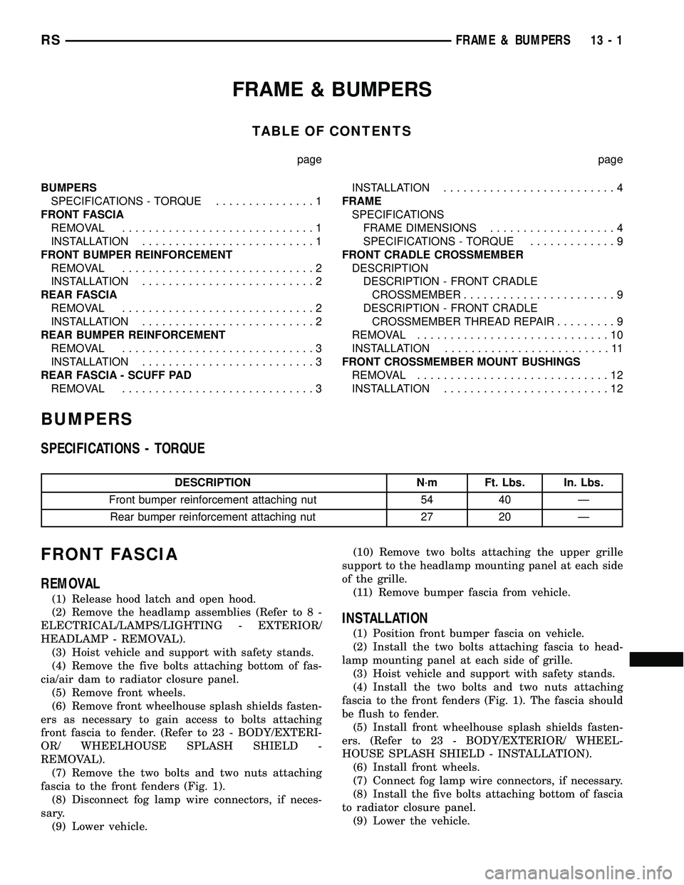
SPECIFICATIONS - TORQUE...............1
FRONT FASCIA
REMOVAL.............................1
INSTALLATION..........................1
FRONT BUMPER REINFORCEMENT
REMOVAL.............................2
INSTALLATION..........................2
REAR FASCIA
REMOVAL.............................2
INSTALLATION..........................2
REAR BUMPER REINFORCEMENT
REMOVAL.............................3
INSTALLATION..........................3
REAR FASCIA - SCUFF PAD
REMOVAL.............................3INSTALLATION..........................4
FRAME
SPECIFICATIONS
FRAME DIMENSIONS...................4
SPECIFICATIONS - TORQUE.............9
FRONT CRADLE CROSSMEMBER
DESCRIPTION
DESCRIPTION - FRONT CRADLE
CROSSMEMBER.......................9
DESCRIPTION - FRONT CRADLE
CROSSMEMBER THREAD REPAIR.........9
REMOVAL.............................10
INSTALLATION.........................11
FRONT CROSSMEMBER MOUNT BUSHINGS
REMOVAL.............................12
INSTALLATION.........................12
BUMPERS
SPECIFICATIONS - TORQUE
DESCRIPTION N´m Ft. Lbs. In. Lbs.
Front bumper reinforcement attaching nut 54 40 Ð
Rear bumper reinforcement attaching nut 27 20 Ð
FRONT FASCIA
REMOVAL
(1) Release hood latch and open hood.
(2) Remove the headlamp assemblies (Refer to 8 -
ELECTRICAL/LAMPS/LIGHTING - EXTERIOR/
HEADLAMP - REMOVAL).
(3) Hoist vehicle and support with safety stands.
(4) Remove the five bolts attaching bottom of fas-
cia/air dam to radiator closure panel.
(5) Remove front wheels.
(6) Remove front wheelhouse splash shields fasten-
ers as necessary to gain access to bolts attaching
front fascia to fender. (Refer to 23 - BODY/EXTERI-
OR/ WHEELHOUSE SPLASH SHIELD -
REMOVAL).
(7) Remove the two bolts and two nuts attaching
fascia to the front fenders (Fig. 1).
(8) Disconnect fog lamp wire connectors, if neces-
sary.
(9) Lower vehicle.(10) Remove two bolts attaching the upper grille
support to the headlamp mounting panel at each side
of the grille.
(11) Remove bumper fascia from vehicle.
INSTALLATION
(1) Position front bumper fascia on vehicle.
(2) Install the two bolts attaching fascia to head-
lamp mounting panel at each side of grille.
(3) Hoist vehicle and support with safety stands.
(4) Install the two bolts and two nuts attaching
fascia to the front fenders (Fig. 1). The fascia should
be flush to fender.
(5) Install front wheelhouse splash shields fasten-
ers. (Refer to 23 - BODY/EXTERIOR/ WHEEL-
HOUSE SPLASH SHIELD - INSTALLATION).
(6) Install front wheels.
(7) Connect fog lamp wire connectors, if necessary.
(8) Install the five bolts attaching bottom of fascia
to radiator closure panel.
(9) Lower the vehicle.
RSFRAME & BUMPERS13-1
Page 1628 of 2585
Misassembled synchronizer components also cause
shifting problems. Incorrectly installed synchronizer
sleeves, keys, balls, or springs can cause shift prob-
lems.
NOISY OPERATION
Transaxle noise is most often a result of worn or
damaged components. Chipped, broken gear or syn-
chronizer teeth, and brinnelled, spalled bearings all
cause noise.
Abnormal wear and damage to the internal compo-
nents is frequently the end result of insufficient
lubricant.
SLIPS OUT OF GEAR
Transaxle disengagement may be caused by mis-
aligned or damaged shift components, or worn teeth
on the drive gears or synchronizer components. Incor-
rect assembly also causes gear disengagement. Check
for missing snap rings.
LOW LUBRICANT LEVEL
Insufficient transaxle lubricant is usually the
result of leaks, or inaccurate fluid level check or refill
method. Leakage is evident by the presence of oil
around the leak point. If leakage is not evident, the
condition is probably the result of an underfill.
If air±powered lubrication equipment is used to fill
a transaxle, be sure the equipment is properly cali-
brated. Equipment out of calibration can lead to an
underfill condition.
CLUTCH PROBLEMS
Worn, damaged, or misaligned clutch components
can cause difficult shifting, gear clash, and noise.
A worn or damaged clutch disc, pressure plate, or
release bearing can cause hard shifting and gear
clash.
REMOVAL
REMOVAL - 2.4L GAS
(1) Raise hood.
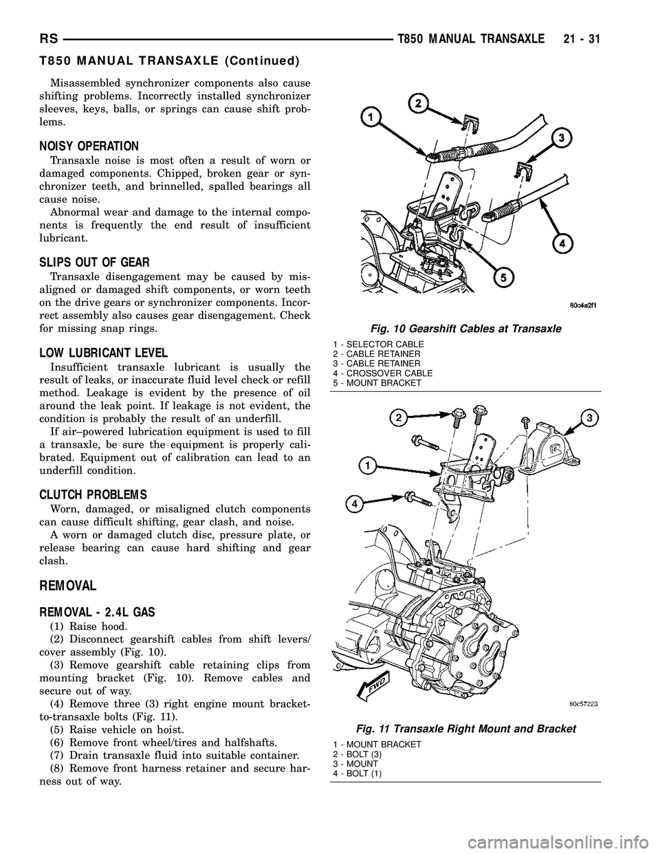
(2) Disconnect gearshift cables from shift levers/
cover assembly (Fig. 10).
(3) Remove gearshift cable retaining clips from
mounting bracket (Fig. 10). Remove cables and
secure out of way.
(4) Remove three (3) right engine mount bracket-
to-transaxle bolts (Fig. 11).
(5) Raise vehicle on hoist.
(6) Remove front wheel/tires and halfshafts.
(7) Drain transaxle fluid into suitable container.
(8) Remove front harness retainer and secure har-
ness out of way.
Fig. 10 Gearshift Cables at Transaxle
1 - SELECTOR CABLE
2 - CABLE RETAINER
3 - CABLE RETAINER
4 - CROSSOVER CABLE
5 - MOUNT BRACKET
Fig. 11 Transaxle Right Mount and Bracket
1 - MOUNT BRACKET
2 - BOLT (3)
3 - MOUNT
4 - BOLT (1)
RST850 MANUAL TRANSAXLE21-31
T850 MANUAL TRANSAXLE (Continued)
Page 2123 of 2585
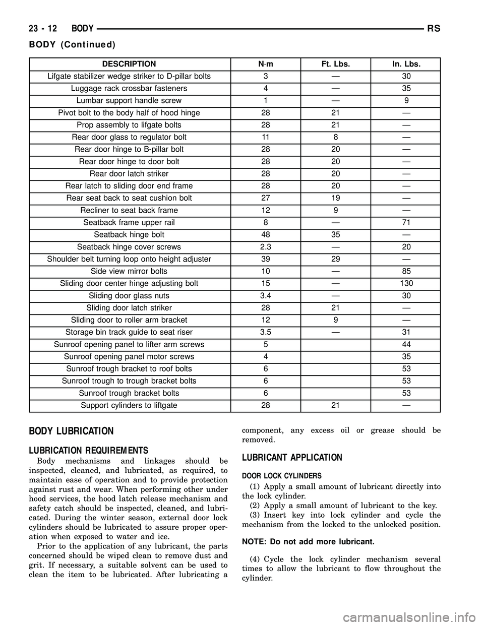
DESCRIPTION N´m Ft. Lbs. In. Lbs.
Lifgate stabilizer wedge striker to D-pillar bolts 3 Ð 30
Luggage rack crossbar fasteners 4 Ð 35
Lumbar support handle screw 1 Ð 9
Pivot bolt to the body half of hood hinge 28 21 Ð
Prop assembly to lifgate bolts 28 21 Ð
Rear door glass to regulator bolt 11 8 Ð
Rear door hinge to B-pillar bolt 28 20 Ð
Rear door hinge to door bolt 28 20 Ð
Rear door latch striker 28 20 Ð
Rear latch to sliding door end frame 28 20 Ð
Rear seat back to seat cushion bolt 27 19 Ð
Recliner to seat back frame 12 9 Ð
Seatback frame upper rail 8 Ð 71
Seatback hinge bolt 48 35 Ð
Seatback hinge cover screws 2.3 Ð 20
Shoulder belt turning loop onto height adjuster 39 29 Ð
Side view mirror bolts 10 Ð 85
Sliding door center hinge adjusting bolt 15 Ð 130
Sliding door glass nuts 3.4 Ð 30
Sliding door latch striker 28 21 Ð
Sliding door to roller arm bracket 12 9 Ð
Storage bin track guide to seat riser 3.5 Ð 31
Sunroof opening panel to lifter arm screws 5 44
Sunroof opening panel motor screws 4 35
Sunroof trough bracket to roof bolts 6 53
Sunroof trough to trough bracket bolts 6 53
Sunroof trough bracket bolts 6 53
Support cylinders to liftgate 28 21 Ð
BODY LUBRICATION
LUBRICATION REQUIREMENTS
Body mechanisms and linkages should be
inspected, cleaned, and lubricated, as required, to
maintain ease of operation and to provide protection
against rust and wear. When performing other under
hood services, the hood latch release mechanism and
safety catch should be inspected, cleaned, and lubri-
cated. During the winter season, external door lock
cylinders should be lubricated to assure proper oper-
ation when exposed to water and ice.
Prior to the application of any lubricant, the parts
concerned should be wiped clean to remove dust and
grit. If necessary, a suitable solvent can be used to
clean the item to be lubricated. After lubricating acomponent, any excess oil or grease should be
removed.LUBRICANT APPLICATION
DOOR LOCK CYLINDERS
(1) Apply a small amount of lubricant directly into
the lock cylinder.
(2) Apply a small amount of lubricant to the key.
(3) Insert key into lock cylinder and cycle the
mechanism from the locked to the unlocked position.
NOTE: Do not add more lubricant.
(4) Cycle the lock cylinder mechanism several
times to allow the lubricant to flow throughout the
cylinder.
23 - 12 BODYRS
BODY (Continued)
Page 2161 of 2585
COWL GRILLE
REMOVAL
(1) Remove wiper arms. (Refer to 8 - ELECTRI-
CAL/WIPERS/WASHERS/WIPER ARMS -
REMOVAL)
(2) Remove four (4) screws securing cowl cover to
wiper module (Fig. 6).
(3) Disengage quarter turn fasteners at outboard
ends of cowl grill from body.
(4) Release hood latch and open hood.
CAUTION: To prevent hood scratching of cowl grille
before removal, cover outboard exterior ends of
cowl grille with masking tape or equivalent method.
NOTE: Do not over bend cowl grille during removal.
Bend cowl grille just enough to clear top of wiper
pivot shaft and bottom rear corner of hood.
(5) Remove cowl grill by raising above driver side
wiper pivot shaft and swinging away towards engine
compartment. The cowl grille will need to be bent onoutboard end to clear simultaneously top of wiper
pivot shaft and bottom corner of hood.
(6) Close hood. Do not latch. Remove outboard
screws. (Fig. 7).
(7) Disconnect washer hose in line connector.
(8) Disconnect washer hose and grommet from
hole in wiper module and pull out.
(9) Remove cowl grille by raising over opposite
wiper pivot shaft and removing away from vehicle.
(10) Remove cowl cover from vehicle.
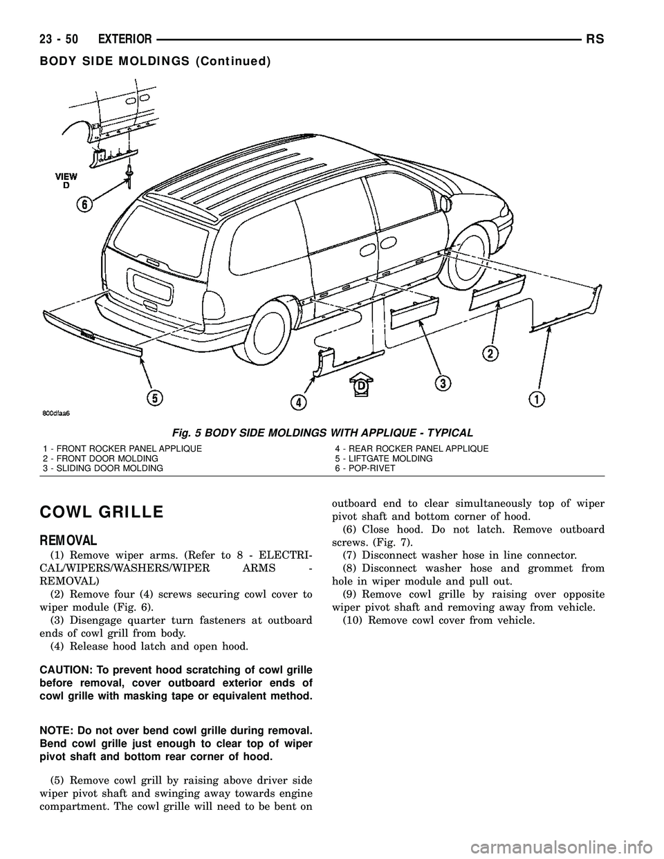
Fig. 5 BODY SIDE MOLDINGS WITH APPLIQUE - TYPICAL
1 - FRONT ROCKER PANEL APPLIQUE
2 - FRONT DOOR MOLDING
3 - SLIDING DOOR MOLDING4 - REAR ROCKER PANEL APPLIQUE
5 - LIFTGATE MOLDING
6 - POP-RIVET
23 - 50 EXTERIORRS
BODY SIDE MOLDINGS (Continued)
Page 2165 of 2585
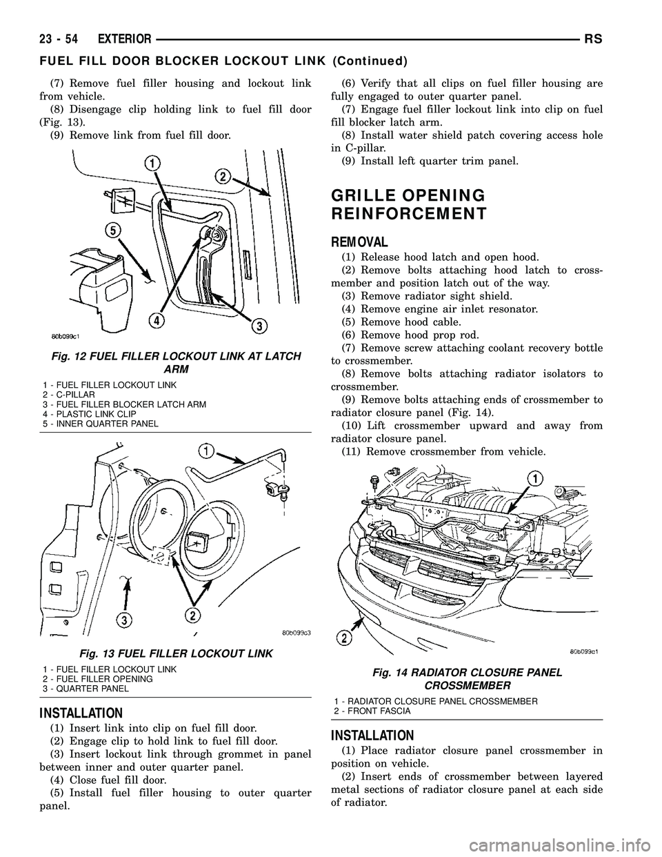
(7) Remove fuel filler housing and lockout link
from vehicle.
(8) Disengage clip holding link to fuel fill door
(Fig. 13).
(9) Remove link from fuel fill door.
INSTALLATION
(1) Insert link into clip on fuel fill door.
(2) Engage clip to hold link to fuel fill door.
(3) Insert lockout link through grommet in panel
between inner and outer quarter panel.
(4) Close fuel fill door.
(5) Install fuel filler housing to outer quarter
panel.(6) Verify that all clips on fuel filler housing are
fully engaged to outer quarter panel.
(7) Engage fuel filler lockout link into clip on fuel
fill blocker latch arm.
(8) Install water shield patch covering access hole
in C-pillar.
(9) Install left quarter trim panel.
GRILLE OPENING
REINFORCEMENT
REMOVAL
(1) Release hood latch and open hood.
(2) Remove bolts attaching hood latch to cross-
member and position latch out of the way.
(3) Remove radiator sight shield.
(4) Remove engine air inlet resonator.
(5) Remove hood cable.
(6) Remove hood prop rod.
(7) Remove screw attaching coolant recovery bottle
to crossmember.
(8) Remove bolts attaching radiator isolators to
crossmember.
(9) Remove bolts attaching ends of crossmember to
radiator closure panel (Fig. 14).
(10) Lift crossmember upward and away from
radiator closure panel.
(11) Remove crossmember from vehicle.
INSTALLATION
(1) Place radiator closure panel crossmember in
position on vehicle.
(2) Insert ends of crossmember between layered
metal sections of radiator closure panel at each side
of radiator.
Fig. 12 FUEL FILLER LOCKOUT LINK AT LATCH
ARM
1 - FUEL FILLER LOCKOUT LINK
2 - C-PILLAR
3 - FUEL FILLER BLOCKER LATCH ARM
4 - PLASTIC LINK CLIP
5 - INNER QUARTER PANEL
Fig. 13 FUEL FILLER LOCKOUT LINK
1 - FUEL FILLER LOCKOUT LINK
2 - FUEL FILLER OPENING
3 - QUARTER PANELFig. 14 RADIATOR CLOSURE PANEL
CROSSMEMBER
1 - RADIATOR CLOSURE PANEL CROSSMEMBER
2 - FRONT FASCIA
23 - 54 EXTERIORRS
FUEL FILL DOOR BLOCKER LOCKOUT LINK (Continued)
Page 2171 of 2585
HOOD
TABLE OF CONTENTS
page page
HINGE
REMOVAL.............................60
INSTALLATION.........................60
HOOD
REMOVAL.............................60
INSTALLATION.........................61
LATCH
REMOVAL.............................61INSTALLATION.........................61
LATCH RELEASE CABLE
REMOVAL.............................61
INSTALLATION.........................62
LATCH STRIKER
REMOVAL.............................62
INSTALLATION.........................62
HINGE
REMOVAL
(1) Remove Front Wiper Unit (Refer to 8 - ELEC-
TRICAL/WIPERS/WASHERS/WIPER MODULE -
REMOVAL) for procedure.
(2) Raise hood.
(3) Mark all bolt and hinge attachment locations
with a grease pencil or other suitable device to pro-
vide reference marks for installation.
(4) Remove pivot bolt from the body half of hood
hinge and use suitable device to support the hood.
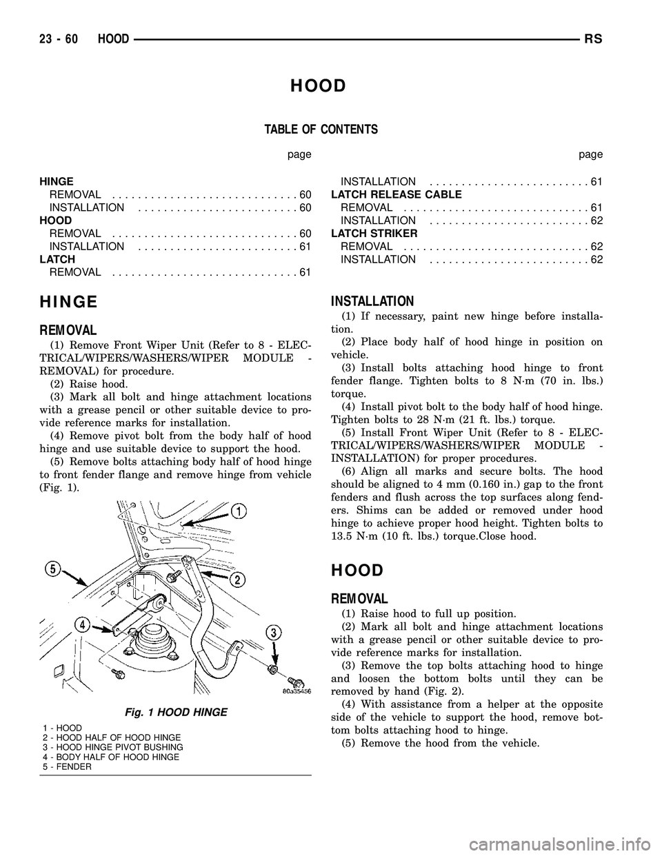
(5) Remove bolts attaching body half of hood hinge
to front fender flange and remove hinge from vehicle
(Fig. 1).
INSTALLATION
(1) If necessary, paint new hinge before installa-
tion.
(2) Place body half of hood hinge in position on
vehicle.
(3) Install bolts attaching hood hinge to front
fender flange. Tighten bolts to 8 N´m (70 in. lbs.)
torque.
(4) Install pivot bolt to the body half of hood hinge.
Tighten bolts to 28 N´m (21 ft. lbs.) torque.
(5) Install Front Wiper Unit (Refer to 8 - ELEC-
TRICAL/WIPERS/WASHERS/WIPER MODULE -
INSTALLATION) for proper procedures.
(6) Align all marks and secure bolts. The hood
should be aligned to 4 mm (0.160 in.) gap to the front
fenders and flush across the top surfaces along fend-
ers. Shims can be added or removed under hood
hinge to achieve proper hood height. Tighten bolts to
13.5 N´m (10 ft. lbs.) torque.Close hood.
HOOD
REMOVAL
(1) Raise hood to full up position.
(2) Mark all bolt and hinge attachment locations
with a grease pencil or other suitable device to pro-
vide reference marks for installation.
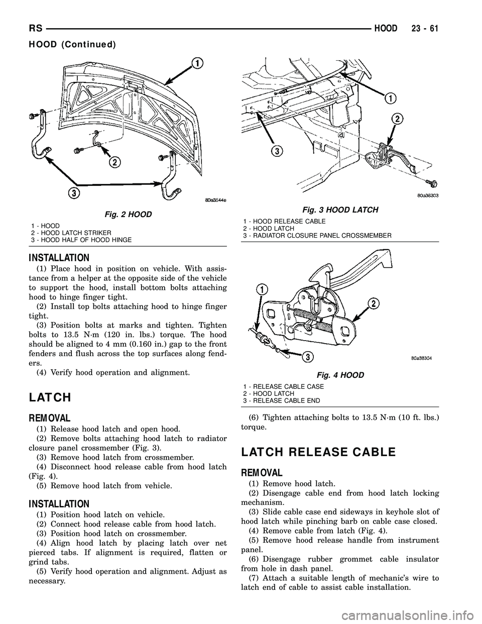
(3) Remove the top bolts attaching hood to hinge
and loosen the bottom bolts until they can be
removed by hand (Fig. 2).
(4) With assistance from a helper at the opposite
side of the vehicle to support the hood, remove bot-
tom bolts attaching hood to hinge.
(5) Remove the hood from the vehicle.
Fig. 1 HOOD HINGE
1 - HOOD
2 - HOOD HALF OF HOOD HINGE
3 - HOOD HINGE PIVOT BUSHING
4 - BODY HALF OF HOOD HINGE
5 - FENDER
23 - 60 HOODRS
Page 2172 of 2585
INSTALLATION
(1) Place hood in position on vehicle. With assis-
tance from a helper at the opposite side of the vehicle
to support the hood, install bottom bolts attaching
hood to hinge finger tight.
(2) Install top bolts attaching hood to hinge finger
tight.
(3) Position bolts at marks and tighten. Tighten
bolts to 13.5 N´m (120 in. lbs.) torque. The hood
should be aligned to 4 mm (0.160 in.) gap to the front
fenders and flush across the top surfaces along fend-
ers.
(4) Verify hood operation and alignment.
LATCH
REMOVAL
(1) Release hood latch and open hood.
(2) Remove bolts attaching hood latch to radiator
closure panel crossmember (Fig. 3).
(3) Remove hood latch from crossmember.
(4) Disconnect hood release cable from hood latch
(Fig. 4).
(5) Remove hood latch from vehicle.
INSTALLATION
(1) Position hood latch on vehicle.
(2) Connect hood release cable from hood latch.
(3) Position hood latch on crossmember.
(4) Align hood latch by placing latch over net
pierced tabs. If alignment is required, flatten or
grind tabs.
(5) Verify hood operation and alignment. Adjust as
necessary.(6) Tighten attaching bolts to 13.5 N´m (10 ft. lbs.)
torque.
LATCH RELEASE CABLE
REMOVAL
(1) Remove hood latch.
(2) Disengage cable end from hood latch locking
mechanism.
(3) Slide cable case end sideways in keyhole slot of
hood latch while pinching barb on cable case closed.
(4) Remove cable from latch (Fig. 4).
(5) Remove hood release handle from instrument
panel.
(6) Disengage rubber grommet cable insulator
from hole in dash panel.
(7) Attach a suitable length of mechanic's wire to
latch end of cable to assist cable installation.
Fig. 2 HOOD
1 - HOOD
2 - HOOD LATCH STRIKER
3 - HOOD HALF OF HOOD HINGE
Fig. 3 HOOD LATCH
1 - HOOD RELEASE CABLE
2 - HOOD LATCH
3 - RADIATOR CLOSURE PANEL CROSSMEMBER
Fig. 4 HOOD
1 - RELEASE CABLE CASE
2 - HOOD LATCH
3 - RELEASE CABLE END
RSHOOD23-61
HOOD (Continued)
Page 2173 of 2585
(8) Route cable back from latch through engine
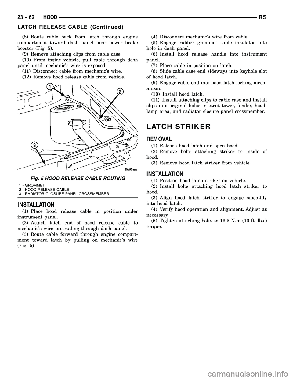
compartment toward dash panel near power brake
booster (Fig. 5).
(9) Remove attaching clips from cable case.
(10) From inside vehicle, pull cable through dash
panel until mechanic's wire is exposed.
(11) Disconnect cable from mechanic's wire.
(12) Remove hood release cable from vehicle.
INSTALLATION
(1) Place hood release cable in position under
instrument panel.
(2) Attach latch end of hood release cable to
mechanic's wire protruding through dash panel.
(3) Route cable forward through engine compart-
ment toward latch by pulling on mechanic's wire
(Fig. 5).(4) Disconnect mechanic's wire from cable.
(5) Engage rubber grommet cable insulator into
hole in dash panel.
(6) Install hood release handle into instrument
panel.
(7) Place cable in position on latch.
(8) Slide cable case end sideways into keyhole slot
of hood latch.
(9) Engage cable end into hood latch locking mech-
anism.
(10) Install hood latch.
(11) Install attaching clips to cable case and install
clips into original holes in strut tower, fender, head-
lamp area, and radiator closure panel crossmember.
LATCH STRIKER
REMOVAL
(1) Release hood latch and open hood.
(2) Remove bolts attaching striker to inside of
hood.
(3) Remove hood latch striker from vehicle.
INSTALLATION
(1) Position hood latch striker on vehicle.
(2) Install bolts attaching hood latch striker to
hood.
(3) Align hood latch striker to engage smoothly
into hood latch.
(4) Verify hood operation and alignment. Adjust as
necessary.
(5) Tighten attaching bolts to 13.5 N´m (10 ft. lbs.)
torque.Fig. 5 HOOD RELEASE CABLE ROUTING
1 - GROMMET
2 - HOOD RELEASE CABLE
3 - RADIATOR CLOSURE PANEL CROSSMEMBER
23 - 62 HOODRS
LATCH RELEASE CABLE (Continued)