2004 CHRYSLER VOYAGER glove box
[x] Cancel search: glove boxPage 664 of 2585

OPERATION
The passenger airbag is equipped with two infla-
tors, each with three levels of pressure output. The
inflators seal the hole in the airbag cushion so it can
discharge the gas it produces directly into the cush-
ion when supplied with the proper electrical signal.
Following an airbag deployment, the airbag cushion
quickly deflates by venting this gas through the
cushion material towards the instrument panel.
The passenger airbag is secured with screws to the
instrument panel beneath the instrument panel top
pad and above the glove box opening. The instrument
panel top pad above the glove box opening conceals
the airbag door and a predetermined hinge line
beneath its decorative cover. Upon airbag deploy-
ment, the top pad will bend at the hinge line and the
door will fold back out of the way onto the top of the
instrument panel.
When the front airbag system is deployed, the fol-
lowingMUSTbe replaced:
²Complete Steering Column Assembly.
²Lower Steering Column Coupler.
²Steering Wheel.
²Clock Spring.
²Driver Airbag.
²Passenger Airbag.
²Upper Instrument Panel with Pad.
CARE OF UNDEPLOYED AIRBAGS
Airbags must be stored in their original special
container until used for service. At no time should a
source of electricity be permitted near the inflator on
the back of an airbag. When carrying or handling an
undeployed airbag, the trim side of the airbag should
be pointing away from the body to minimize possibil-
ity of injury if accidental deployment occurs. Do not
place undeployed airbag face down on a solid surface,
the airbag will propel into the air if accidental
deployment occurs.
REMOVAL
DEPLOYED AIRBAG
(1) Clean powder residue from interior of vehicle
(Refer to 8 - ELECTRICAL/RESTRAINTS - STAN-
DARD PROCEDURE - SERVICE AFTER AN AIR-
BAG DEPLOYMENT).
(2) Remove instrument panel (Refer to 23 - BODY/
INSTRUMENT PANEL/INSTRUMENT PANEL
ASSEMBLY - REMOVAL).
(3) Remove all reusable components from the
upper instrument panel and transfer to the new
instrument panel.
UNDEPLOYED AIRBAG
(1) Open hood.
(2) Disconnect and isolate the battery negative
cable.
(3) Wait two minutes for the airbag system reserve
capacitor to discharge before attempting any airbag
or instrument panel service.
(4) Remove center console bin between front seats.
(5) Remove left front door sill plate using a trim
stick (special tool #C-4755) or equivalent, and gently
prying up on sill plate.
(6) Remove left cowl panel using a trim stick or
equivalent, and gently prying out on cowl panel.
(7) Remove four screws to lower steering column
cover and remove cover.
(8) Unsnap parking brake lever from knee blocker
reinforcement.
(9) Remove Data Link Connector (DLC) from knee
blocker.
(10) Remove screws to knee blocker.
(11) Unsnap left A-pillar lower extension trim
using a trim stick or equivalent.
(12) Remove three left side instrument panel A-pil-
lar retaining bolts and loosen the instrument panel
roll down bolt.
(13) Remove four nuts at brake pedal support
bracket to instrument panel.
(14) Using a trim stick or equivalent, gently pry
off left side upper A-pillar trim.
(15) Remove six screws and two wiring connectors
to lower instrument panel cubby bin at bottom of
center stack.
(16) Remove two left side nuts at instrument panel
center stack support to floor.
(17) Remove two right side nuts at instrument
panel center stack support to floor.
(18) Remove right front door sill plate using a trim
stick or equivalent, and gently prying up on sill
plate.
(19) Remove right cowl panel using a trim stick or
equivalent, and gently prying out on cowl panel.
(20) Using a trim stick or equivalent, gently pry
out on right instrument panel end cap.
(21) Unsnap right A-pillar lower extension trim
using a trim stick or equivalent.
(22) Remove three right side instrument panel
A-pillar retaining bolts and loosen the instrument
panel roll down bolt.
(23) Using a trim stick or equivalent, gently pry
off right side upper A-pillar trim.
(24) Open glove box, pinch in sides and roll down
towards floor. With a firm pull, snap glove box door
off hinges and remove.
(25) Using a trim stick or equivalent, gently pry
up on rear of instrument panel top cover and then
pull rearward and out.
RSRESTRAINTS8O-9
PASSENGER AIRBAG (Continued)
Page 665 of 2585

(26) Using a trim stick or equivalent, gently pry
off the filler bezel just above the cup holder to expose
the lower screws to center bezel.
(27) Remove two screws and then using a trim
stick or equivalent, gently pry off instrument panel
center bezel.
(28) Remove center bezel wiring connectors to
HVAC control and switch assembly (hazard, rear
wiper/washer, heated seats) and remove bezel.
(29) Slide cup holder assembly from instrument
panel.
(30) Remove nineteen screws to right lower instru-
ment panel trim (glove box surround), unplug glove
box lamp wire connector, and remove panel.
(31) Remove four screws and wiring connectors to
radio and remove radio.
(32) Remove one far left instrument panel speaker
retaining screw.
(33) Remove four screws along top front edge of
instrument panel cover/pad.
(34) Remove seven lower instrument panel cover/
pad retaining screws starting from right of vehicle
and only removing these seven, not all of them.
(35) Remove six upper fence line instrument panel
retaining bolts.
(36) Roll back instrument panel just enough to
increase access to the passenger airbag retaining
bolts at the reinforcement. Lift the instrument panel
up slightly so as not to damage the air distribution to
HVAC unit seal.
(37) Disconnect the passenger airbag electrical
connector. Using a trim stick or equivalent, gently
pry electrical connector off of instrument panel rein-
forcement.
(38) Remove the two passenger airbag to instru-
ment panel cover/pad retaining screws.
(39) Remove the three passenger airbag to instru-
ment panel reinforcement retaining bolts.
(40) Pull rearward slightly on the instrument
panel cover/pad to maneuver passenger airbag out
from reinforcement and instrument panel.
INSTALLATION
DEPLOYED AIRBAG
Transfer all reusable components to the new
instrument panel.
(1) Install new Passenger Airbag into instrument
panel.
(2) Install airbag attaching bolts to the instrument
panel.
(a) Torque the two bolts at instrument panel
retainer bosses to 2.7 .5 N´m (24 5 in. lbs.).
(b) Torque the three bolts that attach the pas-
senger airbag to cross-car beam to 10 2 N´m (90
15 in. lbs.).(3) Connect yellow wire connector to passenger air-
bag and affix connector to instrument panel rein-
forcement with push pins.
(4) Install Instrument panel (Refer to 23 - BODY/
INSTRUMENT PANEL/INSTRUMENT PANEL
ASSEMBLY - INSTALLATION).
WARNING: DO NOT CONNECT THE BATTERY NEG-
ATIVE CABLE (Refer to 8 - ELECTRICAL/RE-
STRAINTS - DIAGNOSIS AND TESTING).
PERSONAL INJURY OR DEATH MAY RESULT IF
THE SYSTEM TEST IS NOT PERFORMED PROP-
ERLY.
UNDEPLOYED AIRBAG
(1) Pull rearward slightly on the instrument panel
cover/pad to maneuver passenger airbag up onto
reinforcement and instrument panel.
(2) Install the three passenger airbag to instru-
ment panel reinforcement retaining bolts but leave
loose. This will help align the passenger airbag for
the cover/pad fit.
(3) Install the two passenger airbag to instrument
panel cover/pad retaining screws. Torque screws to
2.7 .5 N´m (24 5 in. lbs.).
NOTE: Insure that the instrument panel cover/pad
locator pins are indexed properly at center stack
area prior to reassembly.
(4) Tighten the three passenger airbag to instru-
ment panel reinforcement retaining bolts. Torque
bolts to 10 2 N´m (90 15 in. lbs.).
(5) Connect the passenger airbag electrical connec-
tor. Install the connector onto the instrument panel
reinforcement with the push-pin fasteners.
(6) Roll the instrument panel forward lifting
slightly so as to seat the instrument panel air distri-
bution duct on top of the HVAC unit properly to
avoid any leaks or damage to the seal.
(7) Install six upper fence line instrument panel
retaining bolts.
(8) Install three right side instrument panel A-pil-
lar retaining bolts and tighten the right instrument
panel roll down bolt. Install the smaller 10 mm bolt
first to align the instrument panel properly.
(9) Install three left side instrument panel A-pillar
retaining bolts and tighten the left instrument panel
roll down bolt. Install the smaller 10 mm bolt first to
align the instrument panel properly.
(10) Install seven lower instrument panel cover/
pad retaining screws.
(11) Install four screws along top front edge of
instrument panel cover/pad.
(12) Install one far left instrument panel speaker
retaining screw.
8O - 10 RESTRAINTSRS
PASSENGER AIRBAG (Continued)
Page 666 of 2585

(13) Install wiring connectors to radio. Install
radio and four retaining screws.
(14) Connect glove box lamp wiring connector and
place right lower instrument panel trim (glove box
surround) into position.
(15) Install nineteen right lower instrument panel
trim (glove box surround) and install panel screws.
(16) Slide cup holder assembly into instrument
panel.
(17) Install center bezel wiring connectors to
HVAC control and switch assembly (hazard, rear
wiper/washer, heated seats).
(18) Install instrument panel center bezel by align-
ing slots and firmly snapping into place.
(19) Install two screws to instrument panel center
bezel.
(20) Align filler bezel above cup holder over retain-
ing slots and firmly snap into place.
(21) Place instrument panel top cover into position
and firmly snap down rear edge of top cover.
(22) Install glove box. Align hinges, snap into
place, roll glove box upwards and push in sides to
fully install.
(23) Align right side upper A-pillar trim over
retaining slots and firmly snap into place.
(24) Align right A-pillar lower extension trim over
retaining slots and firmly snap into place.
(25) Align right instrument panel end cap over
retaining slots and firmly snap into place.
(26) Align right cowl panel over retaining slots and
firmly snap into place.
(27) Align right front door sill plate over retaining
slots and firmly snap into place.
(28) Install two right side nuts at instrument
panel center stack support to floor.
(29) Install two left side nuts at instrument panel
center stack support to floor.
(30) Connect the two wiring connectors to lower
instrument panel cubby bin at bottom of center stack
and install six screws.
(31) Align left side upper A-pillar trim over retain-
ing slots and firmly snap into place.
(32) Install four nuts at brake pedal support
bracket to instrument panel.
(33) Align left A-pillar lower extension trim over
retaining slots and firmly snap into place.
(34) Install knee blocker and retaining screws.
(35) Install Data Link Connector (DLC) into bot-
tom of knee blocker.
(36) Align parking brake lever and snap into place
on knee blocker reinforcement.
(37) Install lower steering column cover and four
retaining screws
(38) Align left cowl panel over retaining slots and
firmly snap into place.(39) Align left front door sill plate over retaining
slots and firmly snap into place.
(40) Install center console bin between front seats.
WARNING: DO NOT CONNECT THE BATTERY NEG-
ATIVE CABLE (Refer to 8 - ELECTRICAL/RE-
STRAINTS - DIAGNOSIS AND TESTING).
PERSONAL INJURY OR DEATH MAY RESULT IF
THE SYSTEM TEST IS NOT PERFORMED PROP-
ERLY.
(41) Close hood.
(42) Verify system and vehicle operation.
SEAT AIRBAG
DESCRIPTION
The side impact airbag system Seat Airbags are
located in the outboard side of the front seat backs.
One in each front seat. The seat airbag inflator
assembly is within the airbag housing (Fig. 5). Each
airbag is mounted to the seat back frame. If deployed
or defective, the entire seat back assembly must be
replaced.
OPERATION
Only the Side Impact Airbag Control Module
(SIACM) can deploy the side airbags. When supplied
with the proper electrical signal, the seat airbag
inflator will produce a gas and discharge the bag
directly between the occupant and the side of the
vehicle, protecting the occupant. Upon deployment,
Fig. 5 SEAT AIRBAG - TYPICAL
RSRESTRAINTS8O-11
PASSENGER AIRBAG (Continued)
Page 1292 of 2585

8W-97 POWER DISTRIBUTION SYSTEM
TABLE OF CONTENTS
page page
POWER DISTRIBUTION SYSTEM
DESCRIPTION..........................1
OPERATION............................1
SPECIAL TOOLS
POWER DISTRIBUTION SYSTEMS.........1
INTEGRATED POWER MODULE
DESCRIPTION..........................2
OPERATION............................2
REMOVAL.............................2
INSTALLATION..........................3IOD FUSE
DESCRIPTION..........................3
OPERATION............................3
POWER OUTLET
DESCRIPTION..........................4
OPERATION............................4
DIAGNOSIS AND TESTING
DIAGNOSIS & TESTING - POWER OUTLET . . 4
REMOVAL.............................5
INSTALLATION..........................5
POWER DISTRIBUTION
SYSTEM
DESCRIPTION
This group covers the various standard and
optional power distribution components used on this
model. The power distribution system for this vehicle
consists of the following components:
²Integrated Power Module (IPM)
²Front Control Module (FCM)
²Power Outlets
Refer to Wiring Diagrams for complete circuit sche-
matics.
The power distribution system also incorporates
various types of circuit control and protection fea-
tures, including:
²Automatic resetting circuit breakers
²Blade-type fuses
²Bus bars
²Cartridge fuses
²Circuit splice blocks
²Flashers
²Fusible links
²Relays
Following are general descriptions of the major
components in the power distribution system. See the
owner's manual in the vehicle glove box for more
information on the features and use of all of the
power distribution system components.
OPERATION
The power distribution system for this vehicle is
designed to provide safe, reliable, and centralized dis-
tribution points for the electrical current required to
operate all of the many standard and optional facto-
ry-installed electrical and electronic powertrain,
chassis, safety, security, comfort and convenience sys-
tems. At the same time, the power distribution sys-
tem was designed to provide ready access to these
electrical distribution points for the vehicle techni-
cian to use when conducting diagnosis and repair of
faulty circuits. The power distribution system can
also prove useful for the sourcing of additional elec-
trical circuits that may be required to provide the
electrical current needed to operate many accessories
that the vehicle owner may choose to have installed
in the aftermarket.
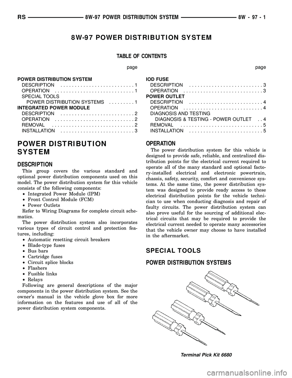
SPECIAL TOOLS
POWER DISTRIBUTION SYSTEMS
Terminal Pick Kit 6680
RS8W-97 POWER DISTRIBUTION SYSTEM8W-97-1
Page 2174 of 2585

INSTRUMENT PANEL
TABLE OF CONTENTS
page page
CLUSTER BEZEL
REMOVAL.............................63
INSTALLATION.........................63
CUP HOLDER
REMOVAL.............................64
INSTALLATION.........................64
GLOVE BOX
REMOVAL.............................64
INSTALLATION.........................64
GLOVE BOX LATCH
REMOVAL.............................64
INSTALLATION.........................64
GLOVE BOX LATCH STRIKER
REMOVAL.............................64
INSTALLATION.........................64
INSTRUMENT PANEL ASSEMBLY
REMOVAL.............................65
INSTALLATION.........................66
INSTRUMENT PANEL CENTER BEZEL
REMOVAL.............................68
INSTALLATION.........................68
INSTRUMENT PANEL END CAP
REMOVAL.............................68INSTALLATION.........................68
INSTRUMENT PANEL TOP COVER
REMOVAL.............................68
INSTALLATION.........................69
LOWER CONSOLE
REMOVAL.............................69
INSTALLATION.........................69
LOWER INSTRUMENT PANEL
REMOVAL.............................69
INSTALLATION.........................69
LOWER STEERING COLUMN COVER
REMOVAL.............................70
INSTALLATION.........................70
STEERING COLUMN COVER BACKING PLATE
REMOVAL.............................70
INSTALLATION.........................70
OVER STEERING COLUMN COVER
REMOVAL.............................70
INSTALLATION.........................70
INSTRUMENT PANEL TOP PAD ASSEMBLY
REMOVAL.............................71
INSTALLATION.........................72
CLUSTER BEZEL
REMOVAL
(1) Disconnect and isolate the battery negative
cable.
(2) Remove Over Steering Column Bezel by lifting
it straight up with a firm pull.
(3) Remove the four bezel attaching screws (Fig.
1).
(4) Tilt the steering column in the full down posi-
tion.
(5) Pull rearward on the cluster bezel and remove.
INSTALLATION
(1) Maneuver cluster bezel over steering column
and into position (Fig. 1).
(2) Install the four bezel attaching screws.
(3) Install the Over Steering Column Bezel by
positioning it over the retaining slots and firmly
snapping it into place.
(4) Connect the battery negative cable.
Fig. 1 CLUSTER BEZEL
1 - INSTRUMENT PANEL
2 - CLUSTER BEZEL
RSINSTRUMENT PANEL23-63
Page 2175 of 2585

CUP HOLDER
REMOVAL
(1) Remove the screw access cover from the bottom
of the center bezel.
(2) Remove the center bezel attaching screws.
(3) Using a trim stick (special tool #C-4755) or
equivalent, gently pry out on the edge of the instru-
ment panel center bezel. Hang off to the side leaving
the accessory switches connected.
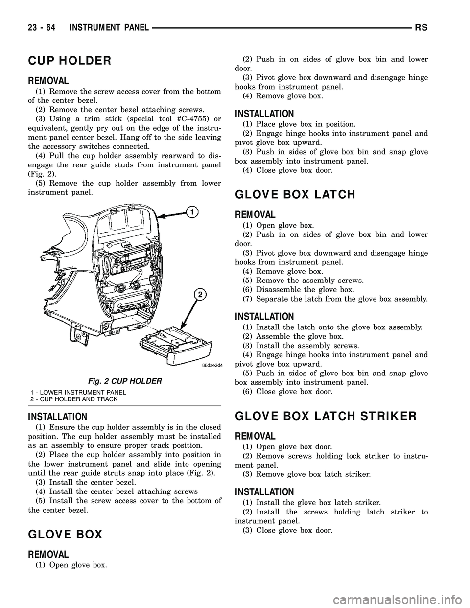
(4) Pull the cup holder assembly rearward to dis-
engage the rear guide studs from instrument panel
(Fig. 2).
(5) Remove the cup holder assembly from lower
instrument panel.
INSTALLATION
(1) Ensure the cup holder assembly is in the closed
position. The cup holder assembly must be installed
as an assembly to ensure proper track position.
(2) Place the cup holder assembly into position in
the lower instrument panel and slide into opening
until the rear guide struts snap into place (Fig. 2).
(3) Install the center bezel.
(4) Install the center bezel attaching screws
(5) Install the screw access cover to the bottom of
the center bezel.
GLOVE BOX
REMOVAL
(1) Open glove box.(2) Push in on sides of glove box bin and lower
door.
(3) Pivot glove box downward and disengage hinge
hooks from instrument panel.
(4) Remove glove box.
INSTALLATION
(1) Place glove box in position.
(2) Engage hinge hooks into instrument panel and
pivot glove box upward.
(3) Push in sides of glove box bin and snap glove
box assembly into instrument panel.
(4) Close glove box door.
GLOVE BOX LATCH
REMOVAL
(1) Open glove box.
(2) Push in on sides of glove box bin and lower
door.
(3) Pivot glove box downward and disengage hinge
hooks from instrument panel.
(4) Remove glove box.
(5) Remove the assembly screws.
(6) Disassemble the glove box.
(7) Separate the latch from the glove box assembly.
INSTALLATION
(1) Install the latch onto the glove box assembly.
(2) Assemble the glove box.
(3) Install the assembly screws.
(4) Engage hinge hooks into instrument panel and
pivot glove box upward.
(5) Push in sides of glove box bin and snap glove
box assembly into instrument panel.
(6) Close glove box door.
GLOVE BOX LATCH STRIKER
REMOVAL
(1) Open glove box door.
(2) Remove screws holding lock striker to instru-
ment panel.
(3) Remove glove box latch striker.
INSTALLATION
(1) Install the glove box latch striker.
(2) Install the screws holding latch striker to
instrument panel.
(3) Close glove box door.
Fig. 2 CUP HOLDER
1 - LOWER INSTRUMENT PANEL
2 - CUP HOLDER AND TRACK
23 - 64 INSTRUMENT PANELRS
Page 2176 of 2585

INSTRUMENT PANEL
ASSEMBLY
REMOVAL
(1) Disconnect and isolate the battery negative
cable.
(2) Remove the lower console:
(a) Remove six retaining screws.
(b) Pull rearward and disconnect the auxiliary
power outlet.
(c) Remove lower console from vehicle.
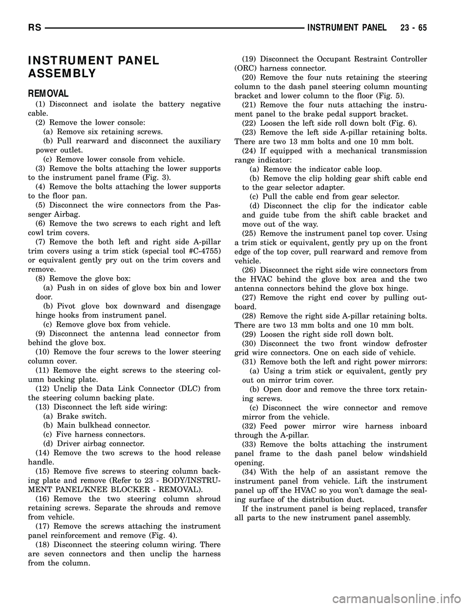
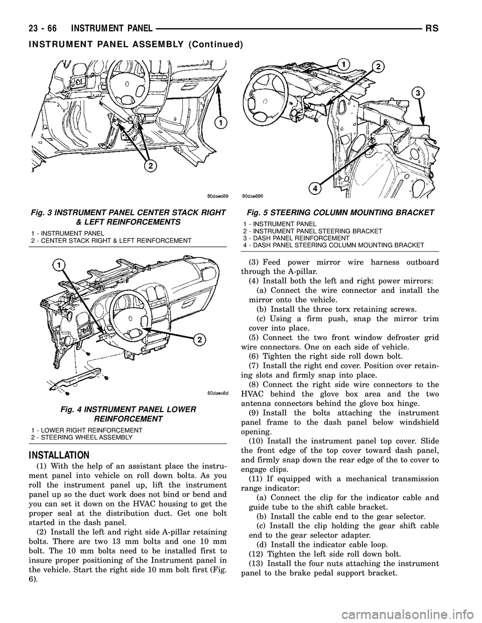
(3) Remove the bolts attaching the lower supports
to the instrument panel frame (Fig. 3).
(4) Remove the bolts attaching the lower supports
to the floor pan.
(5) Disconnect the wire connectors from the Pas-
senger Airbag.
(6) Remove the two screws to each right and left
cowl trim covers.
(7) Remove the both left and right side A-pillar
trim covers using a trim stick (special tool #C-4755)
or equivalent gently pry out on the trim covers and
remove.
(8) Remove the glove box:
(a) Push in on sides of glove box bin and lower
door.
(b) Pivot glove box downward and disengage
hinge hooks from instrument panel.
(c) Remove glove box from vehicle.
(9) Disconnect the antenna lead connector from
behind the glove box.
(10) Remove the four screws to the lower steering
column cover.
(11) Remove the eight screws to the steering col-
umn backing plate.
(12) Unclip the Data Link Connector (DLC) from
the steering column backing plate.
(13) Disconnect the left side wiring:
(a) Brake switch.
(b) Main bulkhead connector.
(c) Five harness connectors.
(d) Driver airbag connector.
(14) Remove the two screws to the hood release
handle.
(15) Remove five screws to steering column back-
ing plate and remove (Refer to 23 - BODY/INSTRU-
MENT PANEL/KNEE BLOCKER - REMOVAL).
(16) Remove the two steering column shroud
retaining screws. Separate the shrouds and remove
from vehicle.
(17) Remove the screws attaching the instrument
panel reinforcement and remove (Fig. 4).
(18) Disconnect the steering column wiring. There
are seven connectors and then unclip the harness
from the column.(19) Disconnect the Occupant Restraint Controller
(ORC) harness connector.
(20) Remove the four nuts retaining the steering
column to the dash panel steering column mounting
bracket and lower column to the floor (Fig. 5).
(21) Remove the four nuts attaching the instru-
ment panel to the brake pedal support bracket.
(22) Loosen the left side roll down bolt (Fig. 6).
(23) Remove the left side A-pillar retaining bolts.
There are two 13 mm bolts and one 10 mm bolt.
(24) If equipped with a mechanical transmission
range indicator:
(a) Remove the indicator cable loop.
(b) Remove the clip holding gear shift cable end
to the gear selector adapter.
(c) Pull the cable end from gear selector.
(d) Disconnect the clip for the indicator cable
and guide tube from the shift cable bracket and
move out of the way.
(25) Remove the instrument panel top cover. Using
a trim stick or equivalent, gently pry up on the front
edge of the top cover, pull rearward and remove from
vehicle.
(26) Disconnect the right side wire connectors from
the HVAC behind the glove box area and the two
antenna connectors behind the glove box hinge.
(27) Remove the right end cover by pulling out-
board.
(28) Remove the right side A-pillar retaining bolts.
There are two 13 mm bolts and one 10 mm bolt.
(29) Loosen the right side roll down bolt.
(30) Disconnect the two front window defroster
grid wire connectors. One on each side of vehicle.
(31) Remove both the left and right power mirrors:
(a) Using a trim stick or equivalent, gently pry
out on mirror trim cover.
(b) Open door and remove the three torx retain-
ing screws.
(c) Disconnect the wire connector and remove
mirror from the vehicle.
(32) Feed power mirror wire harness inboard
through the A-pillar.
(33) Remove the bolts attaching the instrument
panel frame to the dash panel below windshield
opening.
(34) With the help of an assistant remove the
instrument panel from vehicle. Lift the instrument
panel up off the HVAC so you won't damage the seal-
ing surface of the distribution duct.
If the instrument panel is being replaced, transfer
all parts to the new instrument panel assembly.
RSINSTRUMENT PANEL23-65
Page 2177 of 2585

INSTALLATION
(1) With the help of an assistant place the instru-
ment panel into vehicle on roll down bolts. As you
roll the instrument panel up, lift the instrument
panel up so the duct work does not bind or bend and
you can set it down on the HVAC housing to get the
proper seal at the distribution duct. Get one bolt
started in the dash panel.
(2) Install the left and right side A-pillar retaining
bolts. There are two 13 mm bolts and one 10 mm
bolt. The 10 mm bolts need to be installed first to
insure proper positioning of the Instrument panel in
the vehicle. Start the right side 10 mm bolt first (Fig.
6).(3) Feed power mirror wire harness outboard
through the A-pillar.
(4) Install both the left and right power mirrors:
(a) Connect the wire connector and install the
mirror onto the vehicle.
(b) Install the three torx retaining screws.
(c) Using a firm push, snap the mirror trim
cover into place.
(5) Connect the two front window defroster grid
wire connectors. One on each side of vehicle.
(6) Tighten the right side roll down bolt.
(7) Install the right end cover. Position over retain-
ing slots and firmly snap into place.
(8) Connect the right side wire connectors to the
HVAC behind the glove box area and the two
antenna connectors behind the glove box hinge.
(9) Install the bolts attaching the instrument
panel frame to the dash panel below windshield
opening.
(10) Install the instrument panel top cover. Slide
the front edge of the top cover toward dash panel,
and firmly snap down the rear edge of the to cover to
engage clips.
(11) If equipped with a mechanical transmission
range indicator:
(a) Connect the clip for the indicator cable and
guide tube to the shift cable bracket.
(b) Install the cable end to the gear selector.
(c) Install the clip holding the gear shift cable
end to the gear selector adapter.
(d) Install the indicator cable loop.
(12) Tighten the left side roll down bolt.
(13) Install the four nuts attaching the instrument
panel to the brake pedal support bracket.
Fig. 3 INSTRUMENT PANEL CENTER STACK RIGHT
& LEFT REINFORCEMENTS
1 - INSTRUMENT PANEL
2 - CENTER STACK RIGHT & LEFT REINFORCEMENT
Fig. 4 INSTRUMENT PANEL LOWER
REINFORCEMENT
1 - LOWER RIGHT REINFORCEMENT
2 - STEERING WHEEL ASSEMBLY
Fig. 5 STEERING COLUMN MOUNTING BRACKET
1 - INSTRUMENT PANEL
2 - INSTRUMENT PANEL STEERING BRACKET
3 - DASH PANEL REINFORCEMENT
4 - DASH PANEL STEERING COLUMN MOUNTING BRACKET
23 - 66 INSTRUMENT PANELRS
INSTRUMENT PANEL ASSEMBLY (Continued)