2004 CHRYSLER VOYAGER four wheel drive
[x] Cancel search: four wheel drivePage 223 of 2585

tioning valve. The EVBP system uses the ABS sys-
tem to control the slip of the rear wheels in partial
braking range. The braking force of the rear wheels
is controlled electronically by using the inlet and out-
let valves located in the integrated control unit
(ICU).
EVBP activation is invisible to the customer since
there is no pump motor noise or brake pedal feed-
back.
DESCRIPTION - TRACTION CONTROL SYSTEM
Traction control reduces wheel slip and maintains
traction at the driving wheels at speeds below 56
km/h (35 mph) when road surfaces are slippery. The
traction control system reduces wheel slip by braking
the wheel that is losing traction.
HYDRAULIC SHUTTLE VALVES
Two pressure relief hydraulic shuttle valves are
included on vehicles with traction control. These
valves are located inside the HCU and cannot be ser-
viced separately from the HCU.
TRACTION CONTROL LAMP
The traction control function lamp is located in the
transmission range indicator display of the instru-
ment cluster, displaying TRAC, TRAC OFF or nei-
ther depending on system mode.
The TRAC OFF lamp is controlled by a Traction
Control Off switch that is a momentary contact type
switch. The Traction Control Off switch is located on
the steering column upper shroud.
OPERATION
OPERATION - ANTILOCK BRAKE SYSTEM
There are a few performance characteristics of the
Mark 20e Antilock Brake System that may at first
seem abnormal, but in fact are normal. These char-
acteristics are described below.
NORMAL BRAKING
Under normal braking conditions, the ABS func-
tions the same as a standard base brake system with
a diagonally split master cylinder and conventional
vacuum assist.
ABS BRAKING
ABS operation is available at all vehicle speeds
above 3±5 mph. If a wheel locking tendency is
detected during a brake application, the brake system
enters the ABS mode. During ABS braking, hydraulic
pressure in the four wheel circuits is modulated to
prevent any wheel from locking. Each wheel circuit is
designed with a set of electric solenoids to allow mod-ulation, although for vehicle stability, both rear wheel
solenoids receive the same electrical signal. Wheel
lockup may be perceived at the very end of an ABS
stop and is considered normal.
During an ABS stop, the brakes hydraulic system
is still diagonally split. However, the brake system
pressure is further split into three control channels.
During antilock operation of the vehicle's brake sys-
tem, the front wheels are controlled independently
and are on two separate control channels, and the
rear wheels of the vehicle are controlled together.
The system can build and release pressure at each
wheel, depending on signals generated by the wheel
speed sensors (WSS) at each wheel and received at
the controller antilock brake (CAB).
NOISE AND BRAKE PEDAL FEEL
During ABS braking, some brake pedal movement
may be felt. In addition, ABS braking will create
ticking, popping, or groaning noises heard by the
driver. This is normal and is due to pressurized fluid
being transferred between the master cylinder and
the brakes. If ABS operation occurs during hard
braking, some pulsation may be felt in the vehicle
body due to fore and aft movement of the suspension
as brake pressures are modulated.
At the end of an ABS stop, ABS is turned off when
the vehicle is slowed to a speed of 3±4 mph. There
may be a slight brake pedal drop anytime that the
ABS is deactivated, such as at the end of the stop
when the vehicle speed is less than 3 mph or during
an ABS stop where ABS is no longer required. These
conditions exist when a vehicle is being stopped on a
road surface with patches of ice, loose gravel, or sand
on it. Also, stopping a vehicle on a bumpy road sur-
face activates ABS because of the wheel hop caused
by the bumps.
TIRE NOISE AND MARKS
Although the ABS system prevents complete wheel
lockup, some wheel slip is desired in order to achieve
optimum braking performance. Wheel slip is defined
as follows: 0 percent slip means the wheel is rolling
freely and 100 percent slip means the wheel is fully
locked. During brake pressure modulation, wheel slip
is allowed to reach up to 25±30 percent. This means
that the wheel rolling velocity is 25±30 percent less
than that of a free rolling wheel at a given vehicle
speed. This slip may result in some tire chirping,
depending on the road surface. This sound should not
be interpreted as total wheel lockup.
Complete wheel lockup normally leaves black tire
marks on dry pavement. The ABS will not leave dark
black tire marks since the wheel never reaches a
fully locked condition. However, tire marks may be
noticeable as light patched marks.
5 - 76 BRAKES - ABSRS
BRAKES - ABS (Continued)
Page 236 of 2585

HCU (HYDRAULIC CONTROL
UNIT)
DESCRIPTION
The hydraulic control unit (HCU) is mounted to
the CAB as part of the ICU (Fig. 22). The HCU con-
trols the flow of brake fluid to the brakes using a
series of valves and accumulators. A pump/motor is
mounted on the HCU to supply build pressure to the
brakes during an ABS stop.
The HCU on a vehicle equipped with ABS and
traction control has a valve block housing that is
approximately 1 inch longer on the low pressure fluid
accumulators side than a HCU on a vehicle that is
equipped with only ABS.
For more information, (Refer to 5 - BRAKES/HY-
DRAULIC/MECHANICAL/ICU (INTEGRATED CON-
TROL UNIT) - DESCRIPTION)
OPERATION
For information on the operation of the HCU as a
whole, refer to Hydraulic Circuits And Valve Opera-
tion which can be found elsewhere in this section.
For information on the operation of the components
within the HCU, refer to the following three topics.
VALVES AND SOLENOIDS
The valve block contains four inlet valves and four
outlet valves. The inlet valves are spring-loaded in
the open position and the outlet valves are spring-
loaded in the closed position during normal braking.
The fluid is allowed to flow from the master cylinder
to the wheel brakes.
During an ABS stop, these valves cycle to maintain
the proper slip ratio for each wheel. The inlet valve
closes preventing further pressure increase and the
outlet valve opens to provide a path from the wheel
brake to the HCU accumulators and pump/motor.
This releases (decays) pressure from the wheel brake,
thus releasing the wheel from excessive slippage.
Once the wheel is no longer slipping, the outlet valve
is closed and the inlet valve is opened to reapply
(build) pressure.
On vehicles with traction control, there is an extra
set of valves and solenoids. The ASR valves, mounted
in the HCU valve block, are normally in the open
position and close only when the traction control is
applied.
These isolator valves are used to isolate the rear
(non-driving) wheels of the vehicle from the hydraulic
pressure that the HCU pump/motor is sending to the
front (driving) wheels when traction control is being
applied. The rear brakes need to be isolated from the
master cylinder when traction control is being
applied so the rear wheels do not drag. For moreinformation, refer to Traction Control System in this
section.
BRAKE FLUID ACCUMULATORS
There are two fluid accumulators in the HCU±one
for the primary hydraulic circuit and one for the sec-
ondary hydraulic circuit. Each hydraulic circuit uses
a 5 cc accumulator.
The fluid accumulators temporarily store brake
fluid that is removed from the wheel brakes during
an ABS cycle. This stored fluid is used by the pump/
motor to provide build pressure for the brake hydrau-
lic system. When the antilock stop is complete, the
accumulators are drained by the pump/motor.
On ABS-only vehicles, there is a mini-accumulator
on the secondary hydraulic circuit that protects the
master cylinder seals during an ABS stop, and there
is a noise dampening chamber on the primary circuit.
On ABS with traction control vehicles, there are
two noise dampening chambers in the HCU.
PUMP/MOTOR
There are two pump assemblies in the HCUÐone
for the primary hydraulic circuit and one for the sec-
ondary hydraulic circuit. Both pumps are driven by a
common electric motor. This DC-type motor is inte-
gral to the HCU and is controlled by the CAB.
The pump/motor provides the extra amount of
brake fluid needed during antilock braking. Brake
fluid is released to the accumulators when the outlet
valve is opened during an antilock stop. The pump
mechanism consists of two opposing pistons operated
by an eccentric camshaft. In operation, one piston
draws fluid from the accumulators, and the opposing
piston pumps fluid to the master cylinder circuits.
When the antilock stop is complete, the pump/motor
drains the accumulators.
The CAB may turn on the pump/motor when an
antilock stop is detected. The pump/motor continues
to run during the antilock stop and is turned off after
the stop is complete. Under some conditions, the
pump/motor runs to drain the accumulators during
the next drive-off.
The pump/motor is not a serviceable item; if it
requires replacement, the HCU must be replaced.
ICU (INTEGRATED CONTROL
UNIT)
DESCRIPTION
The hydraulic control unit (HCU) and the control-
ler antilock brake (CAB) used with this antilock
brake system are combined (integrated) into one
unit, which is called the integrated control unit (ICU)
RSBRAKES - ABS5-89
Page 246 of 2585

INSTALLATION - PARKING BRAKE CABLE(INTERMEDIATE) ......................66
INSTALLATION - PARKING BRAKE CABLE (RIGHT REAR) ........................66
INSTALLATION - PARKING BRAKE CABLE (LEFT REAR) .........................66
ADJUSTMENTS ADJUSTMENT - PARKING BRAKE CABLES . 66
CABLES - PARKING BRAKE (EXPORT) REMOVAL - FRONT CABLE ...............67
INSTALLATION - FRONT CABLE ............67
LEVER - PARKING BRAKE REMOVAL .............................67 INSTALLATION
.........................67
LEVER - PARKING BRAKE (EXPORT) REMOVAL - PARKING BRAKE LEVER ANDFRONT CABLE .......................68
INSTALLATION - PARKING BRAKE LEVER AND FRONT CABLE ...................69
SHOES - PARKING BRAKE REMOVAL .............................69
INSTALLATION .........................75
ADJUSTMENTS ADJUSTMENT - PARKING BRAKE SHOES . . 76
BRAKES - BASE
DESCRIPTION
DESCRIPTION - BASE BRAKES
The base brake system consists of the following
components: ² Brake pedal
² Power brake booster
² Master cylinder
² Brake tubes and hoses
² Proportioning valve (non-ABS vehicles only)
² Disc brakes
² Drum brakes
² Brake lamp switch
² Brake fluid level switch
² Parking brakes
Front disc brakes control the braking of the front
wheels; rear braking is controlled by rear drum
brakes or rear disc brakes depending on options. The hydraulic brake system is diagonally split on
both the non-antilock braking systems and antilock
braking systems. That means the left front and right
rear brakes are on one hydraulic circuit and the right
front and left rear are on the other. For information on the brake lamp switch, (Refer
to 8 - ELECTRICAL/LAMPS/LIGHTING - EXTERI-
OR/BRAKE LAMP SWITCH - DESCRIPTION) Vehicles equipped with the optional antilock brake
system (ABS) use a system designated Mark 20e. It
is available with or without traction control. This
system shares most base brake hardware used on
vehicles without ABS. ABS components are described
in detail in ANTILOCK BRAKE SYSTEM.
DESCRIPTION - BASE BRAKES (EXPORT)
Four-Wheel Disc Antilock Brakes are standard on
all models.
OPERATION - BASE BRAKES
When a vehicle needs to be stopped, the driver
applies the brake pedal. The brake pedal pushes the
input rod of the power brake booster into the booster.
The booster uses vacuum to ease pedal effort as force
is transferred through the booster to the master cyl-
inder. The booster's output rod pushes in the master
cylinder's primary and secondary pistons applying
hydraulic pressure through the chassis brake tubes
to the brakes at each tire and wheel assembly. The parking brakes are foot-operated. When
applied, the parking brake lever pulls on cables that
actuate brake shoes at each rear wheel. These shoes
come in contact with a hub mounted drum (drum for
disc/drum brakes or drum-in-hat for disc/disc brakes)
and hold it in place.
WARNING
WARNING: DUST AND DIRT ACCUMULATING ON
BRAKE PARTS DURING NORMAL USE MAY CON-
TAIN ASBESTOS FIBERS FROM PRODUCTION OR
AFTERMARKET BRAKE LININGS. BREATHING
EXCESSIVE CONCENTRATIONS OF ASBESTOS
FIBERS CAN CAUSE SERIOUS BODILY HARM.
EXERCISE CARE WHEN SERVICING BRAKE
PARTS. DO NOT SAND OR GRIND BRAKE LINING
UNLESS EQUIPMENT USED IS DESIGNED TO CON-
TAIN THE DUST RESIDUE. DO NOT CLEAN BRAKE
PARTS WITH COMPRESSED AIR OR BY DRY
BRUSHING. CLEANING SHOULD BE DONE BY
DAMPENING THE BRAKE COMPONENTS WITH A
FINE MIST OF WATER, THEN WIPING THE BRAKE
COMPONENTS CLEAN WITH A DAMPENED CLOTH.
DISPOSE OF CLOTH AND ALL RESIDUE CONTAIN-
ING ASBESTOS FIBERS IN AN IMPERMEABLE
CONTAINER WITH THE APPROPRIATE LABEL. FOL-
LOW PRACTICES PRESCRIBED BY THE OCCUPA-
TIONAL SAFETY AND HEALTH ADMINISTRATION
(OSHA) AND THE ENVIRONMENTAL PROTECTION
AGENCY (EPA) FOR THE HANDLING, PROCESSING,
AND DISPOSING OF DUST OR DEBRIS THAT MAY
CONTAIN ASBESTOS FIBERS.
RS BRAKES5s-3
Page 250 of 2585

CONDITION POSSIBLE CAUSES CORRECTION4. Leaking piston seal. 4. Replace piston seal or brake caliper.
5. Suspension problem. 5. Refer to the Suspension group.
PARKING BRAKE -
EXCESSIVE HANDLE
TRAVEL 1. Rear drum brakes or rear disc
brake parking brake shoes out of
adjustment. 1. Adjust rear drum brake shoes, or
rear parking brake shoes on vehicles
with rear disc brakes.
STANDARD PROCEDURE - BASE BRAKE
BLEEDING
NOTE: This bleeding procedure is only for the vehi-
cle's base brakes hydraulic system. For bleeding
the antilock brakes hydraulic system, (Refer to 5 -
BRAKES - ABS - STANDARD PROCEDURE)
CAUTION: Before removing the master cylinder
cover, thoroughly clean the cover and master cylin-
der fluid reservoir to prevent dirt and other foreign
matter from dropping into the master cylinder fluid
reservoir.
NOTE: The following wheel sequence should be
used when bleeding the brake hydraulic system.
The use of this wheel sequence will ensure ade-
quate removal of all trapped air from the brake
hydraulic system.
² Left Rear Wheel
² Right Front Wheel
² Right Rear Wheel
² Left Front Wheel
NOTE: When bleeding the brake system, some air
may be trapped in the brake lines or valves far
upstream, as much as ten feet from the bleeder
screw (Fig. 1). Therefore, it is essential to have a
fast flow of a large volume of brake fluid when
bleeding the brakes to ensure all the air gets out. The brakes may be manually bled or pressure bled.
Refer to the appropriate following procedure.
MANUAL BLEEDING PROCEDURE
NOTE: Correct manual bleeding of the brakes
hydraulic system will require the aid of a helper.
NOTE: To adequately bleed the brakes using the
manual bleeding procedure the rear brakes must be
correctly adjusted. Prior to the manual bleeding of
the brake hydraulic system, correctly adjust the
rear brakes. (1) Pump the brake pedal three or four times and
hold it down before the bleeder screw is opened. (2) Push the brake pedal toward the floor and hold
it down. Then open the left rear bleeder screw at
least 1 full turn. When the bleeder screw opens the
brake pedal will drop all the way to the floor.
CAUTION: ªJust crackingº the bleeder screw often
restricts fluid flow, allowing only a slow, weak fluid
discharge of fluid. This practice will NOT get all the
air out. Make sure the bleeder is opened at least 1
full turn when bleeding.
(3) Release the brake pedal only afterthe bleeder
screw is closed. (4) Repeat steps 1 through 3, four or five times, at
each bleeder screw in the proper sequence. This
should pass a sufficient amount of fluid to expel all
the trapped air from the brake system. Be sure to
monitor the fluid level in the master cylinder, so it
stays at a proper level so air will not enter the brake
system through the master cylinder. (5) Check pedal travel. If pedal travel is excessive
or has not been improved, enough fluid has not
passed through the system to expel all the trapped
air. Continue to bleed system as necessary. (6) Perform a final adjustment of the rear brake
shoes (when applicable), then test drive vehicle to be
sure brakes are operating correctly and that pedal is
solid.
Fig. 1 Trapped Air In Brake Fluid Line
1 - TRAPPED AIR
RS BRAKES5s-7
BRAKES - BASE (Continued)
Page 255 of 2585

DESCRIPTION - DISC BRAKES (REAR)
There are several distinctive features to the rear
disc brakes on this vehicle (Fig. 8). The single piston,
floating caliper rear disc brake system includes a hub
and bearing assembly, adapter, rotor, caliper, and
brake shoes.
This vehicle is equipped with a caliper having a 42
mm (1.65 in.) piston and uses a 15 inch solid non-
vented brake rotor. The brake rotor is described as a
drum-in-hat style because of its dual role as a brak-
ing disc and parking brake drum. The parking brake system on vehicles equipped
with rear disc brakes consists of a small duo-servo
drum brake mounted to the caliper adapter and uses
the interior of the rear disc brake rotor as a drum
(hat section of drum-in-hat style brake rotor). The outboard rear disc brake shoes (pads) are side-
oriented. The shoes are marked indicating which side
they belong on.
DESCRIPTION - DISC BRAKES (EXPORT)
All vehicles are equipped with Four-Wheel-Disc
brakes. Both 15º (BRE) and 16º (BR3) disc/disc brake
systems are available. The disc brakes are manufac-
tured by Continental Teves. The BR3 system is stan-
dard equipment on all-wheel drive and all right-hand
drive models. It is optional on other models. The BR3 system features larger, externally vented
front brake rotors. Although there are different disc/disc systems, they
are serviced using the same service procedures. Some
specifications differ.
DESCRIPTION - DRUM BRAKES (REAR)
This vehicle's rear wheel drum brakes are a two-
shoe, internal-expanding type with an automatic
adjuster screw. The automatic adjuster screw is
located directly below the wheel cylinder that is
mounted near the top of the brake assembly (Fig. 9).
These and two brake shoes (and attaching parts) are
mounted to a support plate at each rear wheel. A
brake drum covers each brake assembly.
OPERATION
OPERATION - DISC BRAKES (FRONT)
When the brakes are applied, fluid pressure is sent
to each brake caliper. The pressure at the caliper is
exerted equally against the caliper piston. The pres-
sure applied to the piston is transmitted directly to
the inboard brake shoe. This forces the shoe lining
against the inner surface of the brake rotor. At the
same time, fluid pressure within the caliper piston
bore forces the caliper to slide inward on its guide
pins. This action brings the outboard shoe lining into
contact with the outer surface of the brake rotor.
This pressure on both sides of the brake rotor causes
friction, bringing the vehicle to a stop. When the brake pedal is released, so is the fluid
pressure. The piston seal inside the caliper is
designed to pull the piston back into the bore of the
caliper when the brake pedal is released (Fig. 10).
This action helps maintain the proper brake shoe-to-
rotor clearance. As disc brake shoe linings wear, master cylinder
reservoir brake fluid level will drop. Adjust as neces-
sary. Fluid level should always be checked after
replacing shoes.
Fig. 8 Rear Disc Brakes
1 - CALIPER
2 - COTTER PIN
3 - ROTOR
4 - NUT RETAINER
5 - OUTER C/V JOINT
Fig. 9 Drum Brake Assembly (Right Shown)
1 - WHEEL CYLINDER
2 - BRAKE SHOE UPPER RETURN SPRING
3 - AUTOMATIC ADJUSTER LEVER
4 - TENSION CLIP
5 - AUTOMATIC ADJUSTER ASSEMBLY
5s - 12 BRAKESRS
HYDRAULIC/MECHANICAL (Continued)
Page 275 of 2585

Use only brake fluid that was stored in a tightly-
sealed container. DO NOT use petroleum-based fluid because seal
damage will result. Petroleum based fluids would be
items such as engine oil, transmission fluid, power
steering fluid etc.
SPECIFICATIONS
BRAKE FLUID
The brake fluid used in this vehicle must conform
to DOT 3 specifications (DOT 4 and DOT 4+ are
acceptable) and SAE J1703 standards. No other type
of brake fluid is recommended or approved for usage
in the vehicle brake system. Use only Mopar tBrake
Fluid or equivalent from a tightly sealed container.
CAUTION: Never use reclaimed brake fluid or fluid
from an container which has been left open. An
open container of brake fluid will absorb moisture
from the air and contaminate the fluid.
CAUTION: Never use any type of a petroleum-based
fluid in the brake hydraulic system. Use of such
type fluids will result in seal damage of the vehicle
brake hydraulic system causing a failure of the
vehicle brake system. Petroleum based fluids would
be items such as engine oil, transmission fluid,
power steering fluid, etc.
JUNCTION BLOCK
DESCRIPTION - NON-ABS JUNCTION BLOCK
A junction block is used on vehicles that are not
equipped with antilock brakes (ABS). The junction
block mounts in the same location as the integrated
control unit (ICU) does on vehicles equipped with
ABS. This allows for use of the same brake tube con-
figuration on all vehicles. The junction block is located
on the driver's side of the front suspension cradle/
crossmember below the master cylinder (Fig. 44).
It has six threaded ports to which the brake tubes
connect. Two are for the primary and secondary
brake tubes coming from the master cylinder. The
remaining four are for the chassis brake tubes going
to each brake assembly.
OPERATION - NON-ABS JUNCTION BLOCK
The junction block distributes the brake fluid com-
ing from the master cylinder primary and secondary
ports to the four chassis brake tubes leading to the
brakes at each wheel. Since the junction block
mounts in the same location as the ABS integrated control unit (ICU), it allows for the common use of
brake tubes going to the brakes whether the vehicle
is equipped with or without ABS.
NOTE: Although the brake tubes coming from the
master cylinder to the junction block or ABS ICU
may appear to be the same, they are not. They are
unique to each brake system application.
REMOVAL - NON-ABS JUNCTION BLOCK
(1) Using a brake pedal depressor, move and lock
the brake pedal to a position past its first 1 inch of
travel. This will prevent brake fluid from draining
out of the master cylinder when the brake tubes are
removed from the junction block. (2) Disconnect the battery negative cable.
(3) If the vehicle is equipped with speed control,
perform the following: (a) Disconnect the battery positive cable.
(b) Remove the battery (Refer t o 8 - ELECTRI-
CAL/BATTERY SYSTEM/BATTERY - REMOVAL). (c) Disconnect the vacuum hose connector at the
tank built into the battery tray. (d) Remove the screw securing the coolant filler
neck to the battery tray. (e) Remove the battery tray (Refer t o 8 - ELEC-
TRICAL/BATTERY SYSTEM/TRAY - REMOVAL). (f) Remove the fasteners and move the speed
control servo off to the side, out of the way.
CAUTION: Before removing the brake tubes from
the junction block, the junction block and the brake
tubes must be thoroughly cleaned. This is required
to prevent contamination from entering the brake
hydraulic system. (4) Remove the four chassis brake tubes from the
top of the junction block (Fig. 44). (5) Remove the primary and secondary brake
tubes from the top of the junction block. (6) Remove the bolts attaching the junction block
mounting bracket to the front suspension crossmem-
ber (Fig. 44), then remove the junction block.
INSTALLATION - NON-ABS JUNCTION BLOCK
(1) Install the junction block and mounting bracket
on the front suspension crossmember (Fig. 44).
Install the mounting bolts and tighten to a torque of
28 N´m (250 in. lbs.). (2) Install the primary and secondary brake tubes
from the master cylinder in their ports. Tighten tube
nuts to a torque of 17 N´m (145 in. lbs.). Take care
not to twist tubes when tightening tube nuts.
They must be properly positioned to allow free
movement with rubber isolated suspension
crossmember.
5s - 32 BRAKESRS
FLUID (Continued)
Page 284 of 2585

(3) Install two upper mounting bolts attaching
pedals assembly to steering column support bracket
on dash panel. Do not fully tighten at this time.
(4) Install four nuts attaching pedals assembly and
power brake booster to dash panel (Fig. 61). (5) Tighten four booster mounting nuts and two
upper mounting bolts to 28 N´m (21 ft. lbs.) torque. (6) Route pedal adjuster cable up and over right
side of pedals assembly and steering column bracket, then down through hole in steering column bracket
as shown (Fig. 60). Attach end of cable to gear box.
(7) Place adjuster cable through loop on right side
of steering column bracket as shown (Fig. 60). (8) Install booster input rod onto brake pedal pin
and install a NEW retaining clip. (9) Connect wiring connector connecting vehicle
wiring harness to pedal wiring harness (Fig. 58). (10) Connect routing clips retaining vehicle wiring
harness to pedal wiring harness (Fig. 58). (11) Install brake lamp switch bracket on pedals
assembly. Tighten mounting nuts to 6 N´m (50 in.
lbs.) torque. (12) Install dash seal silencer shell over steering
column intermediate shaft and fasten in place (Fig.
57). (13) Install steering column onto lower mounting
studs with nuts started, then install column onto
upper mounting studs and install two upper mount-
ing nuts. Tighten upper, then lower mounting nuts to
12 N´m (105 in. lbs.) torque. (14) Install column shaft coupling onto intermedi-
ate shaft and install pinch bolt. Make sure rounded
side of intermediate shaft is matched to the curva-
ture of the coupling. Tighten pinch bolt to 28 N´m
(250 in. lbs.) torque. (15) Remove retainer holding steering wheel in
place on steering column. (16) Attach shift cable to bracket on column.
(17) Connect shift cable end to shift lever mecha-
nism pin (Fig. 55). (18) If equipped, connect PRNDL cable to end of
shift lever mechanism pin and column bracket (Fig.
55). (19) Connect column wiring harness connectors (as
equipped) to SKIM, BTSI solenoid, ignition switch,
multi-function switch, and clockspring. (20) Install lower and upper steering column
shrouds. (Refer to 19 - STEERING/COLUMN/
LOWER SHROUD - INSTALLATION)
CAUTION: Do not reuse the original brake lamp
switch. The switch can only be adjusted once. That
is during initial installation of the switch. If the
switch is not adjusted properly or has been
removed for some service, a new switch must be
installed and adjusted.
(21) Install and adjust NEW brake lamp switch.
(Refer t o 8 - ELECTRICAL/LAMPS/LIGHTING -
EXTERIOR/BRAKE LAMP SWITCH - INSTALLA-
TION) (22) Install instrument panel lower left reinforce-
ment (Fig. 54). (23) Attach hood release to lower left reinforce-
ment.
Fig. 60 Drive Cable Routing
1 - ADJUSTER CABLE
2 - ROUTING LOOP
3 - CABLE ATTACHMENT AT MOTOR
4 - GEAR DRIVE
5 - CABLE ATTACHMENT AT GEAR BOX
6 - STEERING COLUMN BRACKET
Fig. 61 Booster Mounting (Typical)
1 - DASH BRACKET
2 - POWER BRAKE BOOSTER
3 - BRAKE PEDAL ASSEMBLY
RS BRAKES5s-41
PEDALS - ADJUSTABLE (Continued)
Page 296 of 2585
CAUTION: Do not attempt to adjust the height sens-
ing proportioning valve. If found to be defective,
replace the valve.(9) Remove the pressure test fittings and pressure
gauges from the proportioning valve. (10) Install the chassis brake lines in the correct
ports of the proportioning valve. Tighten all tube
nuts to 17 N´m (145 in. lbs.). (11) If necessary, repeat the above steps on the
remaining side of the proportioning valve which con-
trol the other rear wheel brake. (12) Attach the actuator lever and bracket to the
rear axle. (13) Bleed rear brakes. (Refer t o 5 - BRAKES -
STANDARD PROCEDURE) (14) Road test vehicle.
PROPORTIONING VALVE SPECIFICATIONS
WHEELBASE DRIVE
TRAIN SALES
CODE BRAKE
SYSTEM SPLIT
POINT SLOPE INLET
PRESSURE PSI OUTLET
PRESSURE PSI
SWB FWD BRB-BGF 15
9DISC/
DRUM W/O ANTILOCK VAR. 0.59 1000 PSI 675-875 PSI
REMOVAL - PROPORTIONING VALVE (HEIGHT
SENSING)
(1) Using a brake pedal depressor, move and lock
the brake pedal to a position past its first 1 inch of
travel. This will prevent brake fluid from draining
out of the master cylinder when the brake tubes are
removed from the proportioning valve. (2) Raise vehicle. (Refer to LUBRICATION &
MAINTENANCE/HOISTING - STANDARD PROCE-
DURE).
CAUTION: Before removing the brake tubes from
the proportioning valve, the proportioning valve and
the brake tubes must be thoroughly cleaned. This is
required to prevent contamination from entering the
proportioning valve or the brake tubes.
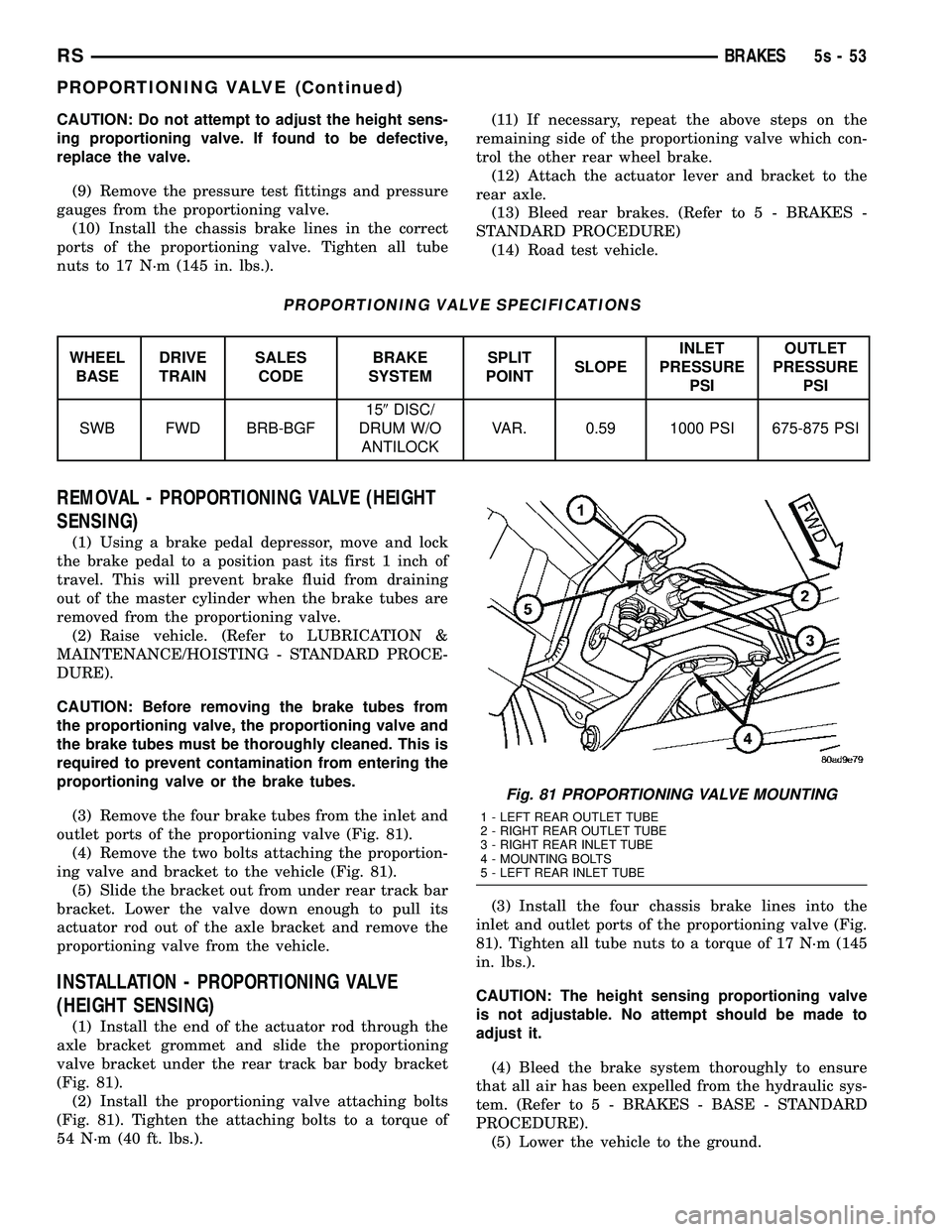
(3) Remove the four brake tubes from the inlet and
outlet ports of the proportioning valve (Fig. 81). (4) Remove the two bolts attaching the proportion-
ing valve and bracket to the vehicle (Fig. 81). (5) Slide the bracket out from under rear track bar
bracket. Lower the valve down enough to pull its
actuator rod out of the axle bracket and remove the
proportioning valve from the vehicle.
INSTALLATION - PROPORTIONING VALVE
(HEIGHT SENSING)
(1) Install the end of the actuator rod through the
axle bracket grommet and slide the proportioning
valve bracket under the rear track bar body bracket
(Fig. 81). (2) Install the proportioning valve attaching bolts
(Fig. 81). Tighten the attaching bolts to a torque of
54 N´m (40 ft. lbs.). (3) Install the four chassis brake lines into the
inlet and outlet ports of the proportioning valve (Fig.
81). Tighten all tube nuts to a torque of 17 N´m (145
in. lbs.).
CAUTION: The height sensing proportioning valve
is not adjustable. No attempt should be made to
adjust it.
(4) Bleed the brake system thoroughly to ensure
that all air has been expelled from the hydraulic sys-
tem. (Refer t o 5 - BRAKES - BASE - STANDARD
PROCEDURE). (5) Lower the vehicle to the ground.
Fig. 81 PROPORTIONING VALVE MOUNTING
1 - LEFT REAR OUTLET TUBE
2 - RIGHT REAR OUTLET TUBE
3 - RIGHT REAR INLET TUBE
4 - MOUNTING BOLTS
5 - LEFT REAR INLET TUBE
RS BRAKES5s-53
PROPORTIONING VALVE (Continued)