2004 CHRYSLER VOYAGER warning
[x] Cancel search: warningPage 2498 of 2585
(9) Use absorbent toweling to clean up any engine
coolant spills from the preceding operation.
(10) Release the four latch tabs that secure the
heater core into the rear HVAC housing.
(11) Carefully pull the heater core straight out of
the rear HVAC housing.
(12) Use absorbent toweling to clean up any
engine coolant spills from the preceding operation.
INSTALLATION
NOTE: If the rear heater core or the rear HVAC
housing have been removed from the vehicle for
service, the rear heater core may be pre-filled with
the proper engine coolant mixture prior to recon-
necting the heater hoses to the heater core hose fit-
tings (Refer to 24 - HEATING & AIR CONDITIONING/
PLUMBING - REAR/HEATER CORE - STANDARD
PROCEDURE - HEATER CORE FILLING).
(1) Carefully slide the heater core into the rear
HVAC housing.
(2) Using hand pressure, press firmly and evenly
on the heater core end plate until the four latch tabs
that secure the heater core in the rear HVAC housing
are fully engaged.
(3) Remove the plugs or tape from the heater core
fittings and both heater hoses.
(4) Reconnect the heater hoses to the rear heater
core (Refer to 24 - HEATING & AIR CONDITION-
ING/PLUMBING - REAR/HEATER HOSE - INSTAL-
LATION).
(5) Install the screw that secures the front of the
rear HVAC housing to the right quarter inner panel.
Tighten the screw to 11 N´m (97 in. lbs.).
(6) Install the screw that secures the back of the
rear HVAC housing to the right D-pillar. Tighten the
screw to 11 N´m (97 in. lbs.).
(7) Install the rear heater distribution duct (Refer
to 24 - HEATING & AIR CONDITIONING/DISTRI-
BUTION - REAR/REAR HEATER DISTRIBUTION
DUCT - INSTALLATION).
(8) Install the right quarter trim panel and right
D-pillar trim panel (Refer to 23 - BODY/INTERIOR/
QUARTER TRIM PANEL - INSTALLATION).
(9) Refill the engine cooling system (Refer to 7 -
COOLING - STANDARD PROCEDURE - COOLING
SYSTEM REFILL).
HEATER HOSES
REMOVAL
WARNING: REFER TO THE APPLICABLE WARN-
INGS AND CAUTIONS FOR THIS SYSTEM BEFORE
PERFORMING THE FOLLOWING OPERATION (Refer
to 24 - HEATING & AIR CONDITIONING/PLUMBING -
WARNING).
(1) Drain the engine cooling system (Refer to 7 -
COOLING - STANDARD PROCEDURE - COOLING
SYSTEM DRAIN).
(2) Using spring tension clamp pliers, compress
and slide the clamps off of each end of the hose being
removed.
CAUTION:
DO NOT apply excessive pressure on heater tubes
or connections when removing heater hoses.
Excessive pressure may damage or deform the
tubes, causing an engine coolant leak.
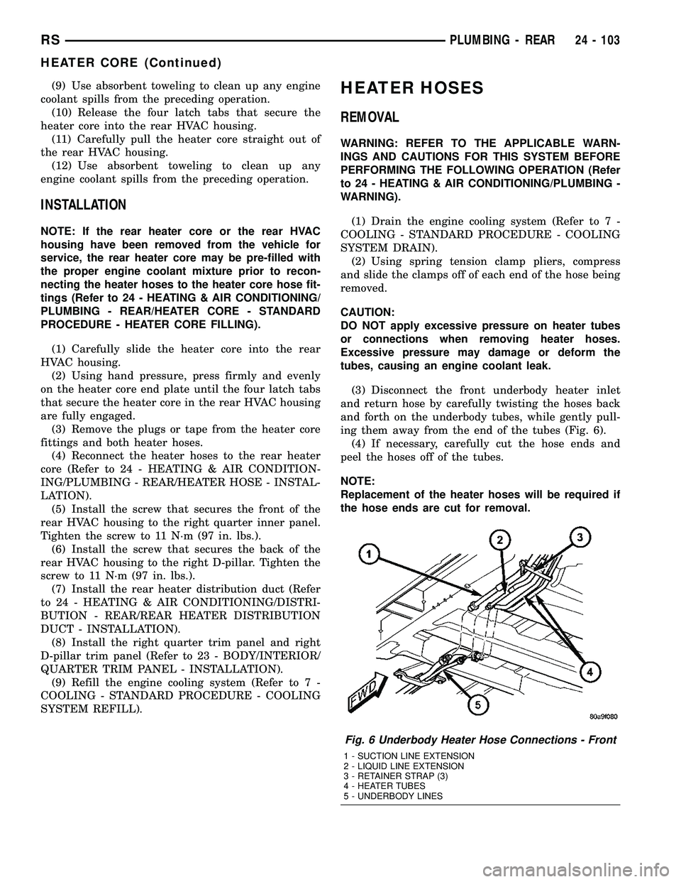
(3) Disconnect the front underbody heater inlet
and return hose by carefully twisting the hoses back
and forth on the underbody tubes, while gently pull-
ing them away from the end of the tubes (Fig. 6).
(4) If necessary, carefully cut the hose ends and
peel the hoses off of the tubes.
NOTE:
Replacement of the heater hoses will be required if
the hose ends are cut for removal.
Fig. 6 Underbody Heater Hose Connections - Front
1 - SUCTION LINE EXTENSION
2 - LIQUID LINE EXTENSION
3 - RETAINER STRAP (3)
4 - HEATER TUBES
5 - UNDERBODY LINES
RSPLUMBING - REAR24 - 103
HEATER CORE (Continued)
Page 2499 of 2585
INSTALLATION
(1) Install the front underbody heater inlet and
return hoses by carefully twisting the hoses back and
forth on the underbody tubes, while gently pushing
them onto the end of the tubes.
CAUTION:
DO NOT apply excessive pressure on heater tubes
or connections when removing heater hoses.
Excessive pressure may damage or deform the
tubes, causing an engine coolant leak.
(2) Using spring tension clamp pliers, compress
and slide the clamps that secure each end of the
heater hose over the tubes. Release the clamp when
it is over the tube.
(3) Refill the engine cooling system (Refer to 7 -
COOLING - STANDARD PROCEDURE - COOLING
SYSTEM REFILL).
LIQUID LINE
REMOVAL
WARNING: REFER TO THE APPLICABLE WARN-
INGS AND CAUTIONS FOR THIS SYSTEM BEFORE
PERFORMING THE FOLLOWING OPERATION (Refer
to 24 - HEATING & AIR CONDITIONING/PLUMBING -
FRONT - WARNING - A/C PLUMBING) and (Refer to
24 - HEATING & AIR CONDITIONING/PLUMBING -
FRONT - CAUTION - A/C PLUMBING).
NOTE: On models equipped with the optional rear
A/C system, the rear section of the front air condi-
tioner liquid line also includes a liquid line hose
and tube extension that connects the front liquid
line to the underbody liquid line for the rear A/C
system.
(1) Recover the refrigerant from the refrigerant
system (Refer to 24 - HEATING & AIR CONDITION-
ING/PLUMBING - FRONT/REFRIGERANT - STAN-
DARD PROCEDURE - REFRIGERANT
RECOVERY).
(2) Disconnect and isolate the battery negative
cable.
(3) Remove the air cleaner housing from the right
side of the engine compartment.
(4) Disconnect the drain tube from the wiper mod-
ule drain on the right side of the engine compart-
ment.
(5) Remove the A/C pressure transducer (Refer to
24 - HEATING & AIR CONDITIONING/CONTROLS
- FRONT/A/C PRESSURE TRANSDUCER -
REMOVAL).(6) If equipped, remove the nut that secures the
A/C ground strap to the weld stud on the top of the
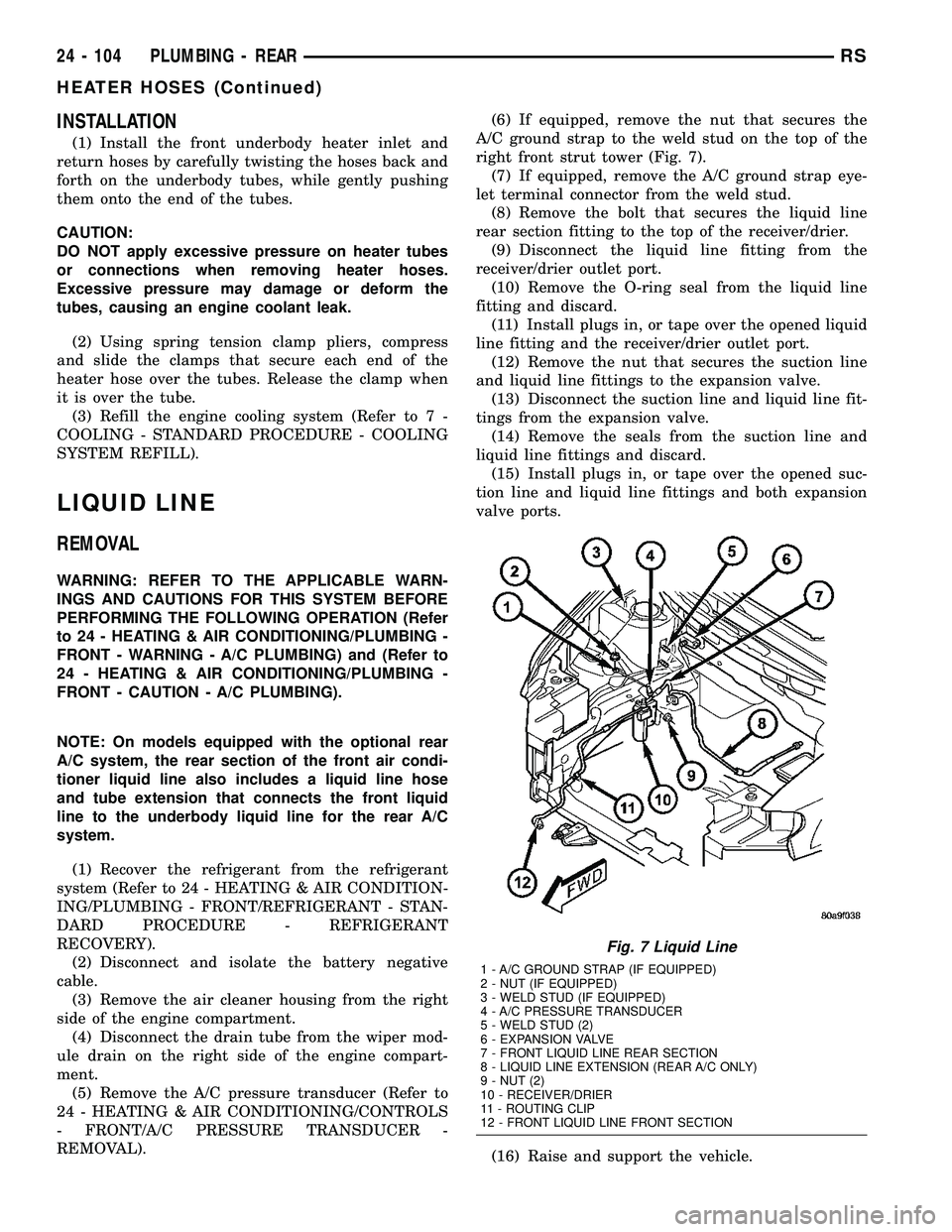
right front strut tower (Fig. 7).
(7) If equipped, remove the A/C ground strap eye-
let terminal connector from the weld stud.
(8) Remove the bolt that secures the liquid line
rear section fitting to the top of the receiver/drier.
(9) Disconnect the liquid line fitting from the
receiver/drier outlet port.
(10) Remove the O-ring seal from the liquid line
fitting and discard.
(11) Install plugs in, or tape over the opened liquid
line fitting and the receiver/drier outlet port.
(12) Remove the nut that secures the suction line
and liquid line fittings to the expansion valve.
(13) Disconnect the suction line and liquid line fit-
tings from the expansion valve.
(14) Remove the seals from the suction line and
liquid line fittings and discard.
(15) Install plugs in, or tape over the opened suc-
tion line and liquid line fittings and both expansion
valve ports.
(16) Raise and support the vehicle.
Fig. 7 Liquid Line
1 - A/C GROUND STRAP (IF EQUIPPED)
2 - NUT (IF EQUIPPED)
3 - WELD STUD (IF EQUIPPED)
4 - A/C PRESSURE TRANSDUCER
5 - WELD STUD (2)
6 - EXPANSION VALVE
7 - FRONT LIQUID LINE REAR SECTION
8 - LIQUID LINE EXTENSION (REAR A/C ONLY)
9 - NUT (2)
10 - RECEIVER/DRIER
11 - ROUTING CLIP
12 - FRONT LIQUID LINE FRONT SECTION
24 - 104 PLUMBING - REARRS
HEATER HOSES (Continued)
Page 2501 of 2585
SUCTION LINE
REMOVAL
On models equipped with the optional rear A/C
system, the front air conditioner suction line also
includes a suction line hose and tube extension that
connects the front suction line to the underbody suc-
tion line for the rear A/C system.
WARNING: REFER TO THE APPLICABLE WARN-
INGS AND CAUTIONS FOR THIS SYSTEM BEFORE
PERFORMING THE FOLLOWING OPERATION (Refer
to 24 - HEATING & AIR CONDITIONING/PLUMBING -
FRONT - WARNING - A/C PLUMBING) and (Refer to
24 - HEATING & AIR CONDITIONING/PLUMBING -
FRONT - CAUTION - A/C PLUMBING).
(1) Recover the refrigerant from the refrigerant
system (Refer to 24 - HEATING & AIR CONDITION-
ING/PLUMBING - FRONT/REFRIGERANT - STAN-
DARD PROCEDURE - REFRIGERANT
RECOVERY).
(2) Disconnect and isolate the battery negative
cable.
(3) Remove the air cleaner top cover and snorkel
from the air cleaner housing located on the right side
of the engine compartment.
(4) Disconnect the drain tube from the wiper mod-
ule drain on the right side of the engine compart-
ment.
(5) Remove the nut that secures the suction line
fitting to the top of the compressor.
(6) Disconnect the suction line fitting from the
compressor suction port.
(7) Remove the seal from the suction line fitting
and discard.
(8) Install plugs in, or tape over the opened suc-
tion line fitting and the compressor suction port.
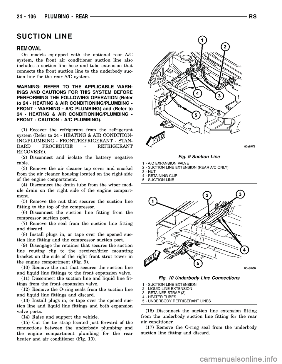
(9) Disengage the retainer that secures the suction
line routing clip to the receiver/drier mounting
bracket on the side of the right front strut tower in
the engine compartment (Fig. 9).
(10) Remove the nut that secures the suction line
and liquid line fittings to the front expansion valve.
(11) Disconnect the suction line and liquid line fit-
tings from the front expansion valve.
(12) Remove the O-ring seals from the suction line
and liquid line fittings and discard.
(13) Install plugs in, or tape over the opened suc-
tion line and liquid line fittings and both expansion
valve ports.
(14) Raise and support the vehicle.
(15) Cut the tie strap located just forward of the
connections between the underbody plumbing and
the engine compartment plumbing for the rear
heater and air conditioner (Fig. 10).(16) Disconnect the suction line extension fitting
from the underbody suction line fitting for the rear
air conditioner.
(17) Remove the O-ring seal from the underbody
suction line fitting and discard.
Fig. 9 Suction Line
1 - A/C EXPANSION VALVE
2 - SUCTION LINE EXTENSION (REAR A/C ONLY)
3 - NUT
4 - RETAINING CLIP
5 - SUCTION LINE
Fig. 10 Underbody Line Connections
1 - SUCTION LINE EXTENSION
2 - LIQUID LINE EXTENSION
3 - RETAINER STRAP (3)
4 - HEATER TUBES
5 - UNDERBODY REFRIGERANT LINES
24 - 106 PLUMBING - REARRS
Page 2504 of 2585
REMOVAL
REMOVAL - UNDERBODY HEATER TUBES
WARNING: REFER TO THE APPLICABLE WARN-
INGS AND CAUTIONS FOR THIS SYSTEM BEFORE
PERFORMING THE FOLLOWING OPERATION (Refer
to 24 - HEATING & AIR CONDITIONING/PLUMBING -
WARNING).
(1) Drain the engine cooling system (Refer to 7 -
COOLING - STANDARD PROCEDURE - COOLING
SYSTEM DRAIN).
(2) Raise and support vehicle.
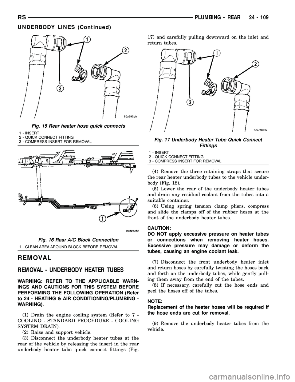
(3) Disconnect the underbody heater tubes at the
rear of the vehicle by releasing the insert in the rear
underbody heater tube quick connect fittings (Fig.17) and carefully pulling downward on the inlet and
return tubes.
(4) Remove the three retaining straps that secure
the rear heater underbody tubes to the vehicle under-
body (Fig. 18).
(5) Lower the rear of the underbody heater tubes
and drain any residual coolant from the tubes into a
suitable container.
(6) Using spring tension clamp pliers, compress
and slide the clamps off of the rubber hoses at the
front of the underbody heater tubes.
CAUTION:
DO NOT apply excessive pressure on heater tubes
or connections when removing heater hoses.
Excessive pressure may damage or deform the
tubes, causing an engine coolant leak.
(7) Disconnect the front underbody heater inlet
and return hoses by carefully twisting the hoses back
and forth on the underbody tubes, while gently pull-
ing them away from the end of the tubes.
(8) If necessary, carefully cut the hose ends and
peel the hoses off of the tubes.
NOTE:
Replacement of the heater hoses will be required if
the hose ends are cut for removal.
(9) Remove the underbody heater tubes from the
vehicle.
Fig. 15 Rear heater hose quick connects
1 - INSERT
2 - QUICK CONNECT FITTING
3 - COMPRESS INSERT FOR REMOVAL
Fig. 16 Rear A/C Block Connection
1 - CLEAN AREA AROUND BLOCK BEFORE REMOVAL
Fig. 17 Underbody Heater Tube Quick Connect
Fittings
1 - INSERT
2 - QUICK CONNECT FITTING
3 - COMPRESS INSERT FOR REMOVAL
RSPLUMBING - REAR24 - 109
UNDERBODY LINES (Continued)
Page 2505 of 2585
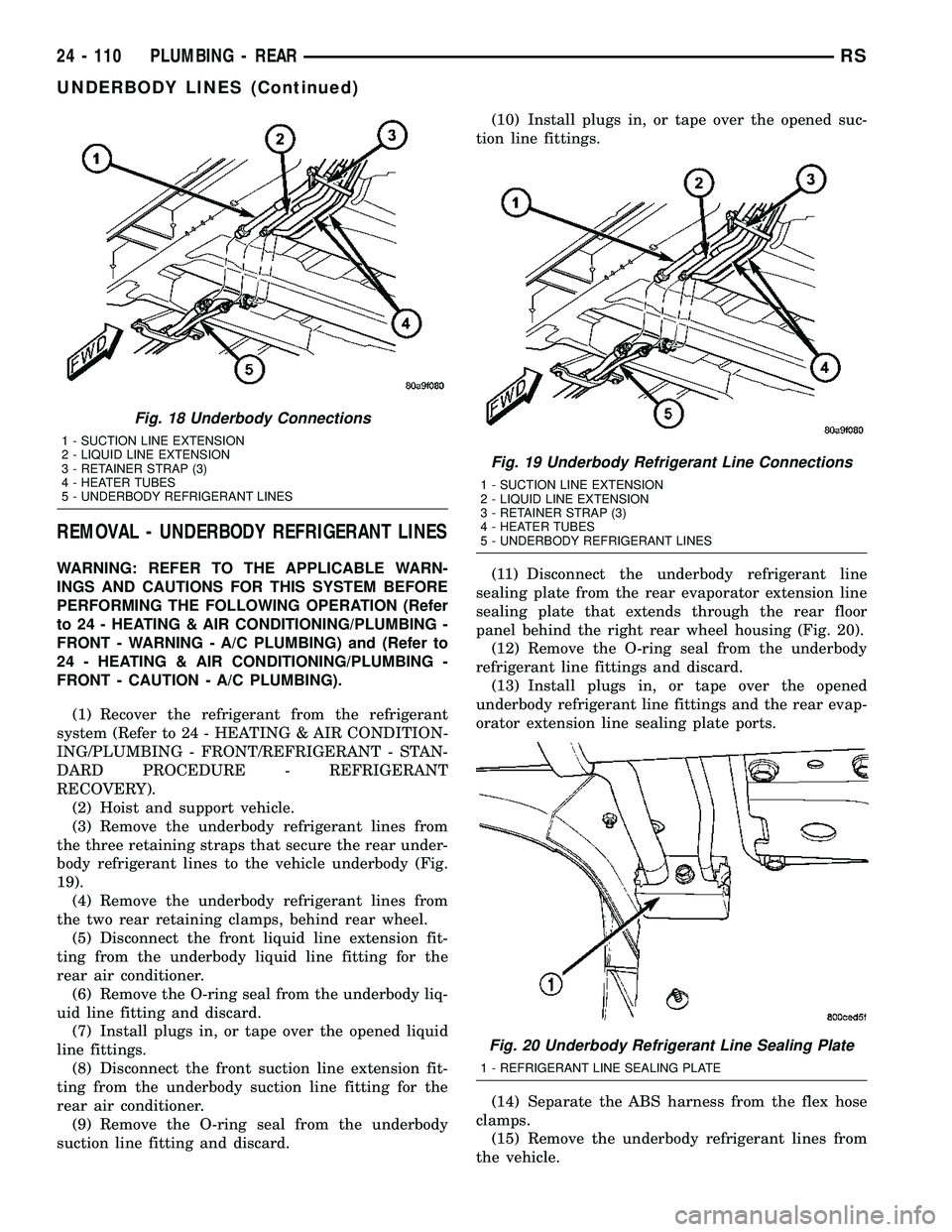
REMOVAL - UNDERBODY REFRIGERANT LINES
WARNING: REFER TO THE APPLICABLE WARN-
INGS AND CAUTIONS FOR THIS SYSTEM BEFORE
PERFORMING THE FOLLOWING OPERATION (Refer
to 24 - HEATING & AIR CONDITIONING/PLUMBING -
FRONT - WARNING - A/C PLUMBING) and (Refer to
24 - HEATING & AIR CONDITIONING/PLUMBING -
FRONT - CAUTION - A/C PLUMBING).
(1) Recover the refrigerant from the refrigerant
system (Refer to 24 - HEATING & AIR CONDITION-
ING/PLUMBING - FRONT/REFRIGERANT - STAN-
DARD PROCEDURE - REFRIGERANT
RECOVERY).
(2) Hoist and support vehicle.
(3) Remove the underbody refrigerant lines from
the three retaining straps that secure the rear under-
body refrigerant lines to the vehicle underbody (Fig.
19).
(4) Remove the underbody refrigerant lines from
the two rear retaining clamps, behind rear wheel.
(5) Disconnect the front liquid line extension fit-
ting from the underbody liquid line fitting for the
rear air conditioner.
(6) Remove the O-ring seal from the underbody liq-
uid line fitting and discard.
(7) Install plugs in, or tape over the opened liquid
line fittings.
(8) Disconnect the front suction line extension fit-
ting from the underbody suction line fitting for the
rear air conditioner.
(9) Remove the O-ring seal from the underbody
suction line fitting and discard.(10) Install plugs in, or tape over the opened suc-
tion line fittings.
(11) Disconnect the underbody refrigerant line
sealing plate from the rear evaporator extension line
sealing plate that extends through the rear floor
panel behind the right rear wheel housing (Fig. 20).
(12) Remove the O-ring seal from the underbody
refrigerant line fittings and discard.
(13) Install plugs in, or tape over the opened
underbody refrigerant line fittings and the rear evap-
orator extension line sealing plate ports.
(14) Separate the ABS harness from the flex hose
clamps.
(15) Remove the underbody refrigerant lines from
the vehicle.
Fig. 18 Underbody Connections
1 - SUCTION LINE EXTENSION
2 - LIQUID LINE EXTENSION
3 - RETAINER STRAP (3)
4 - HEATER TUBES
5 - UNDERBODY REFRIGERANT LINES
Fig. 19 Underbody Refrigerant Line Connections
1 - SUCTION LINE EXTENSION
2 - LIQUID LINE EXTENSION
3 - RETAINER STRAP (3)
4 - HEATER TUBES
5 - UNDERBODY REFRIGERANT LINES
Fig. 20 Underbody Refrigerant Line Sealing Plate
1 - REFRIGERANT LINE SEALING PLATE
24 - 110 PLUMBING - REARRS
UNDERBODY LINES (Continued)
Page 2509 of 2585
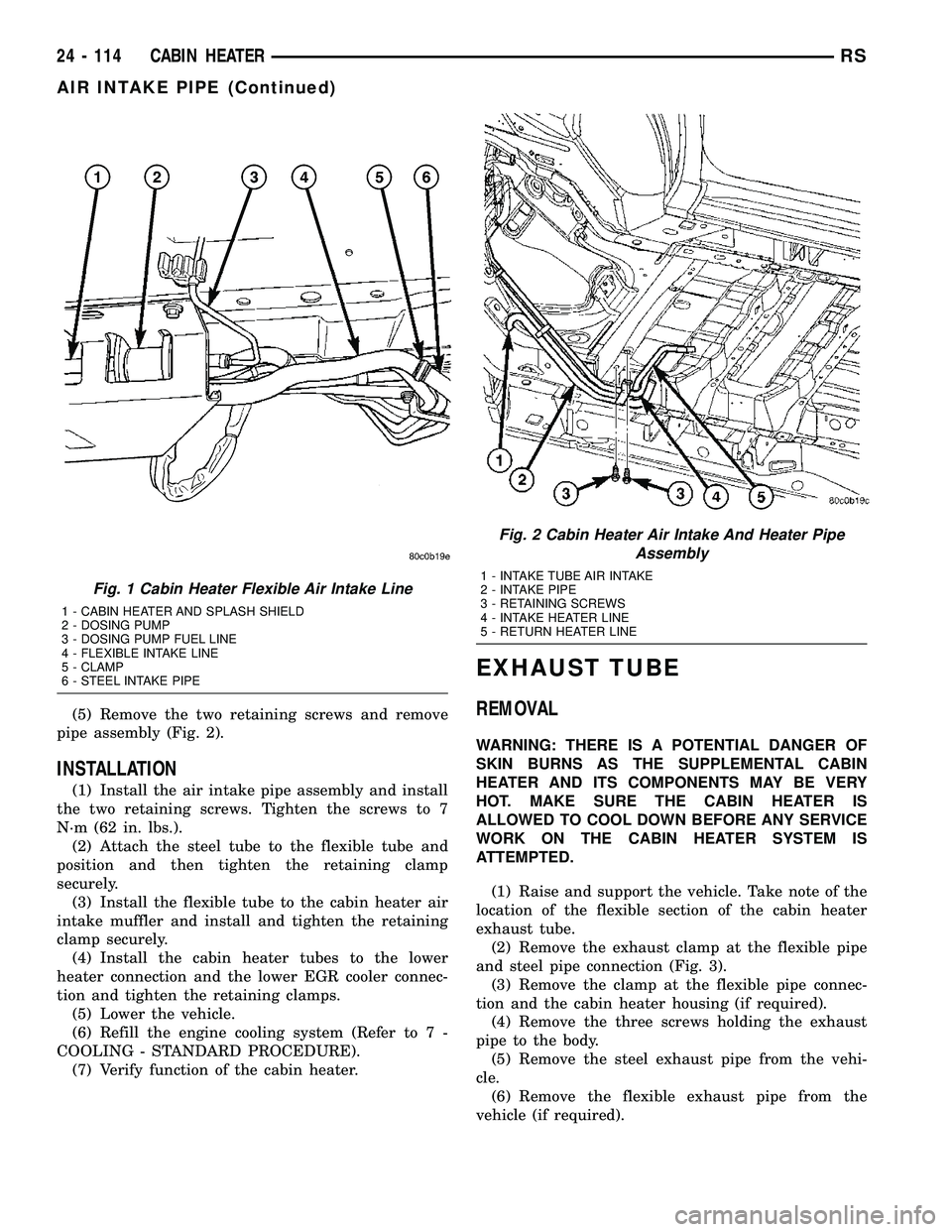
(5) Remove the two retaining screws and remove
pipe assembly (Fig. 2).
INSTALLATION
(1) Install the air intake pipe assembly and install
the two retaining screws. Tighten the screws to 7
N´m (62 in. lbs.).
(2) Attach the steel tube to the flexible tube and
position and then tighten the retaining clamp
securely.
(3) Install the flexible tube to the cabin heater air
intake muffler and install and tighten the retaining
clamp securely.
(4) Install the cabin heater tubes to the lower
heater connection and the lower EGR cooler connec-
tion and tighten the retaining clamps.
(5) Lower the vehicle.
(6) Refill the engine cooling system (Refer to 7 -
COOLING - STANDARD PROCEDURE).
(7) Verify function of the cabin heater.
EXHAUST TUBE
REMOVAL
WARNING: THERE IS A POTENTIAL DANGER OF
SKIN BURNS AS THE SUPPLEMENTAL CABIN
HEATER AND ITS COMPONENTS MAY BE VERY
HOT. MAKE SURE THE CABIN HEATER IS
ALLOWED TO COOL DOWN BEFORE ANY SERVICE
WORK ON THE CABIN HEATER SYSTEM IS
ATTEMPTED.
(1) Raise and support the vehicle. Take note of the
location of the flexible section of the cabin heater
exhaust tube.
(2) Remove the exhaust clamp at the flexible pipe
and steel pipe connection (Fig. 3).
(3) Remove the clamp at the flexible pipe connec-
tion and the cabin heater housing (if required).
(4) Remove the three screws holding the exhaust
pipe to the body.
(5) Remove the steel exhaust pipe from the vehi-
cle.
(6) Remove the flexible exhaust pipe from the
vehicle (if required).
Fig. 1 Cabin Heater Flexible Air Intake Line
1 - CABIN HEATER AND SPLASH SHIELD
2 - DOSING PUMP
3 - DOSING PUMP FUEL LINE
4 - FLEXIBLE INTAKE LINE
5 - CLAMP
6 - STEEL INTAKE PIPE
Fig. 2 Cabin Heater Air Intake And Heater Pipe
Assembly
1 - INTAKE TUBE AIR INTAKE
2 - INTAKE PIPE
3 - RETAINING SCREWS
4 - INTAKE HEATER LINE
5 - RETURN HEATER LINE
24 - 114 CABIN HEATERRS
AIR INTAKE PIPE (Continued)
Page 2513 of 2585
INSTALLATION
WARNING: DO NOT OPERATE THE DIESEL SUP-
PLEMENTAL CABIN HEATER IN AN ENCLOSED
AREA SUCH AS A GARAGE THAT DOES NOT HAVE
EXHAUST VENTILATION FACILITIES. ALWAYS VENT
THE CABIN HEATER EXHAUST WHEN OPERATING
THE CABIN HEATER. ALLOW THE DIESEL SUPPLE-
MENTAL CABIN HEATER TO COOL BEFORE PER-
FORMING ANY SERVICE PROCEDURES TO THE
CABIN HEATER. VERIFY THAT ALL DIESEL SUP-
PLEMENTAL CABIN HEATER FUEL LINES ARE
SECURELY FASTENED TO THEIR RESPECTIVE
COMPONENTS BEFORE PERFORMING ANY SER-
VICE PROCEDURES TO THE CABIN HEATER. FAIL-
URE TO FOLLOW THESE INSTRUCTION MAY
RESULT IN PERSONAL INJURY OR DEATH.
NOTE: Verify that there is more than 1/8 of a tank of
fuel in the vehicle's fuel tank before performing this
procedure. Add fuel, if necessary.
(1) Install the cabin heater fuel supply line into
vehicle and fuel line retainers.
(2) Install the fuel line connection at the fuel tank
and tighten the connection securely.
(3) Install the fuel line at the dosing pump and
tighten the connection securely.
(4) Lower the vehicle.
NOTE: Failure to prime the dosing pump after drain-
ing the supplemental cabin fuel line will prevent
cabin heater activation during the first attempt to
start the cabin heater. This will also set a diagnostic
trouble code (DTC) in the cabin heater control's
memory. Do not perform the Dosing Pump Priming
procedure if an attempt was made to start the cabin
heater without priming the dosing pump first. This
will put excess fuel in the cabin heater and cause
smoke to emit from the cabin heater exhaust pipe
when cabin heater activation occurs.
(5) Connect the DRBIIItscan tool to the diagnos-
tic link connector.
(6) Turn the ignition to the ON position.
NOTE: Do not activate the dosing pump prime more
than one time. This will put excess fuel in the sup-
plemental cabin heater and cause smoke to emit
from the cabin heater exhaust pipe when cabin
heater activation occurs.
NOTE: A clicking noise heard coming from the dos-
ing pump indicates that the pump is operational.(7) With the DRBIIItscan tool in Cabin Heater,
select System Tests and Dosing Pump Prime. Allow
the dosing pump to run for the full 45 second cycle
time. When the 45 second cycle is complete, press
Page Back on the DRBIIItscan tool key pad to exit
the Dosing Pump Prime. The Dosing Pump Priming
procedure is now complete.
HEATER UNIT
REMOVAL
WARNING: DO NOT OPERATE THE DIESEL SUP-
PLEMENTAL CABIN HEATER IN AN ENCLOSED
AREA SUCH AS A GARAGE THAT DOES NOT HAVE
EXHAUST VENTILATION FACILITIES. ALWAYS VENT
THE CABIN HEATER EXHAUST WHEN OPERATING
THE CABIN HEATER. ALLOW THE DIESEL SUPPLE-
MENTAL CABIN HEATER TO COOL BEFORE PER-
FORMING ANY SERVICE PROCEDURES TO THE
CABIN HEATER. VERIFY THAT ALL DIESEL SUP-
PLEMENTAL CABIN HEATER FUEL LINES ARE
SECURELY FASTENED TO THEIR RESPECTIVE
COMPONENTS BEFORE PERFORMING ANY SER-
VICE PROCEDURES TO THE CABIN HEATER. FAIL-
URE TO FOLLOW THESE INSTRUCTION MAY
RESULT IN PERSONAL INJURY OR DEATH.
(1) Raise and support the vehicle. Take note of the
location of the flexible section of the cabin heater
exhaust tube.
(2) Drain the engine cooling system (Refer to 7 -
COOLING - STANDARD PROCEDURE).
(3) Carefully open one hose to the underbody tube
assembly and drain the remaining coolant. A salvage
hose is a good idea to control the residual coolant, as
flow will occur from both the cabin heater and the
hose and tube assemblies.
(4) Remove the second hose from the underbody
hose and tube assembly.
(5) Loosen the hose and tube assembly from the
toe-board crossmember at two locations.
(6) Disconnect the electrical connector from the
body harness near the toe-board crossmember and
rail.
(7) Remove the wiring harness from the toe-board
crossmember (Refer to 24 - HEATING & AIR CON-
DITIONING/CABIN HEATER/HEATER UNIT -
REMOVAL).
(8) Open the fuel filler cap. Disconnect the rubber
fuel hose between the body tube assembly and the
fuel pump nipple at the body tube joint. A minimal
amount of fuel may flow from the open port.
NOTE: Utilize an approved fuel storage container to
catch any residual fuel.
24 - 118 CABIN HEATERRS
FUEL LINE (Continued)
Page 2532 of 2585
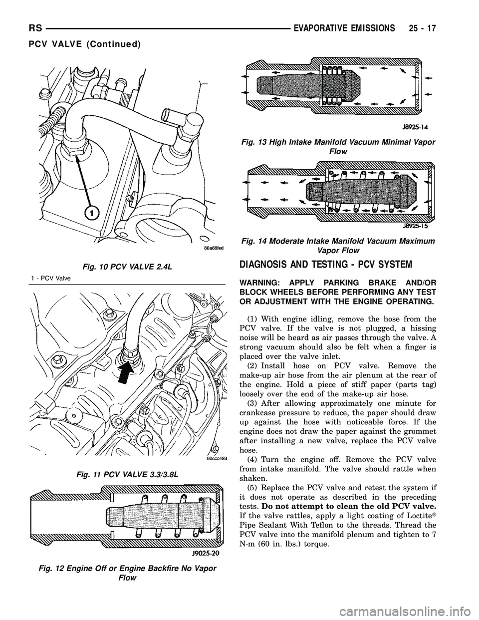
DIAGNOSIS AND TESTING - PCV SYSTEM
WARNING: APPLY PARKING BRAKE AND/OR
BLOCK WHEELS BEFORE PERFORMING ANY TEST
OR ADJUSTMENT WITH THE ENGINE OPERATING.
(1) With engine idling, remove the hose from the
PCV valve. If the valve is not plugged, a hissing
noise will be heard as air passes through the valve. A
strong vacuum should also be felt when a finger is
placed over the valve inlet.
(2) Install hose on PCV valve. Remove the
make-up air hose from the air plenum at the rear of
the engine. Hold a piece of stiff paper (parts tag)
loosely over the end of the make-up air hose.
(3) After allowing approximately one minute for
crankcase pressure to reduce, the paper should draw
up against the hose with noticeable force. If the
engine does not draw the paper against the grommet
after installing a new valve, replace the PCV valve
hose.
(4) Turn the engine off. Remove the PCV valve
from intake manifold. The valve should rattle when
shaken.
(5) Replace the PCV valve and retest the system if
it does not operate as described in the preceding
tests.Do not attempt to clean the old PCV valve.
If the valve rattles, apply a light coating of Loctitet
Pipe Sealant With Teflon to the threads. Thread the
PCV valve into the manifold plenum and tighten to 7
N´m (60 in. lbs.) torque.
Fig. 10 PCV VALVE 2.4L
1 - PCV Valve
Fig. 11 PCV VALVE 3.3/3.8L
Fig. 12 Engine Off or Engine Backfire No Vapor
Flow
Fig. 13 High Intake Manifold Vacuum Minimal Vapor
Flow
Fig. 14 Moderate Intake Manifold Vacuum Maximum
Vapor Flow
RSEVAPORATIVE EMISSIONS25-17
PCV VALVE (Continued)