2004 CHRYSLER VOYAGER Power system
[x] Cancel search: Power systemPage 1447 of 2585
(11) Fill the cooling system. (Refer to 7 - COOL-
ING - STANDARD PROCEDURE)
EXHAUST MANIFOLD - RIGHT
REMOVAL
(1) Disconnect battery negative cable.
(2) Remove the wiper module. (Refer to 8 - ELEC-
TRICAL/WIPERS/WASHERS/WIPER MODULE -
REMOVAL)
(3) Disconnect spark plug wires.
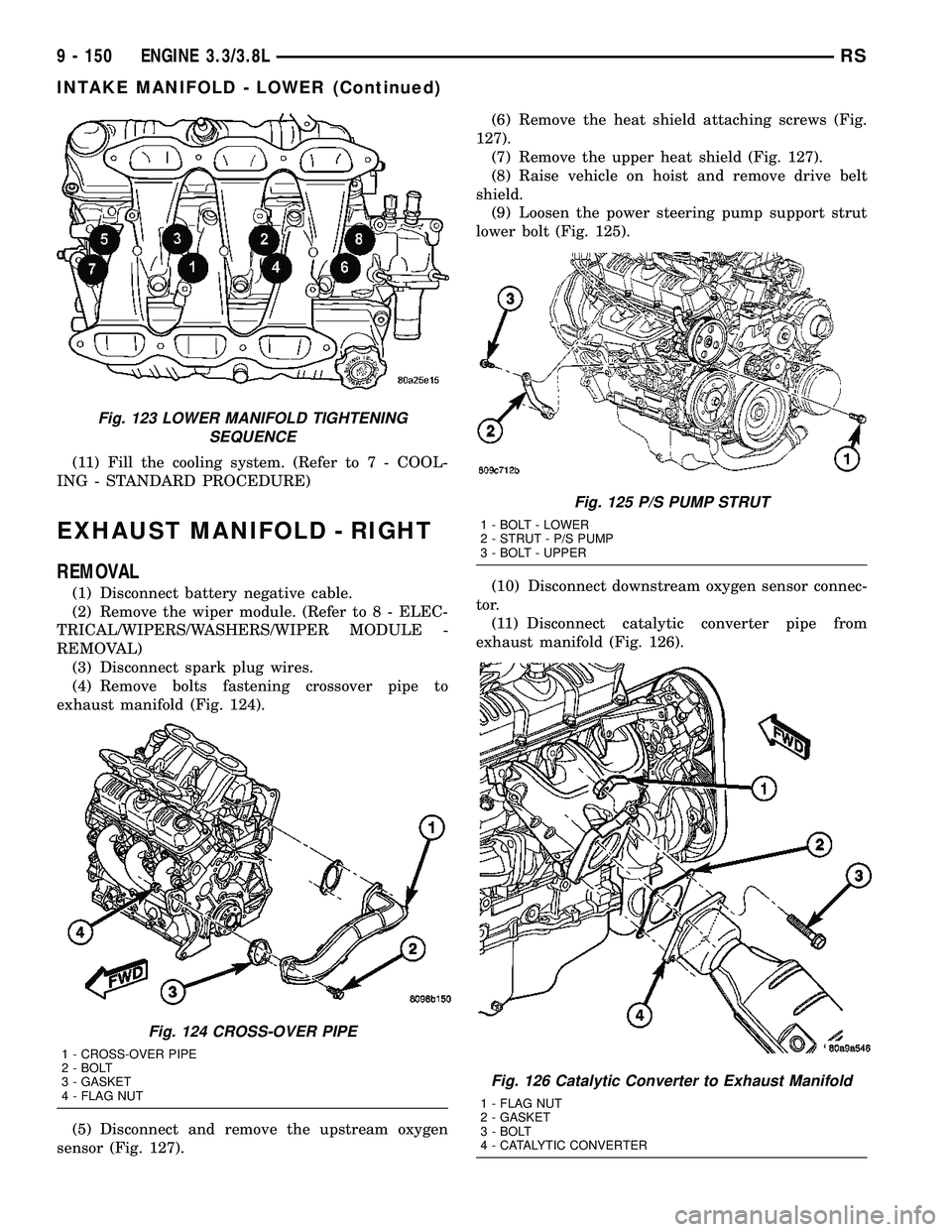
(4) Remove bolts fastening crossover pipe to
exhaust manifold (Fig. 124).
(5) Disconnect and remove the upstream oxygen
sensor (Fig. 127).(6) Remove the heat shield attaching screws (Fig.
127).
(7) Remove the upper heat shield (Fig. 127).
(8) Raise vehicle on hoist and remove drive belt
shield.
(9) Loosen the power steering pump support strut
lower bolt (Fig. 125).
(10) Disconnect downstream oxygen sensor connec-
tor.
(11) Disconnect catalytic converter pipe from
exhaust manifold (Fig. 126).
Fig. 123 LOWER MANIFOLD TIGHTENING
SEQUENCE
Fig. 124 CROSS-OVER PIPE
1 - CROSS-OVER PIPE
2 - BOLT
3 - GASKET
4 - FLAG NUT
Fig. 125 P/S PUMP STRUT
1 - BOLT - LOWER
2 - STRUT - P/S PUMP
3 - BOLT - UPPER
Fig. 126 Catalytic Converter to Exhaust Manifold
1 - FLAG NUT
2 - GASKET
3 - BOLT
4 - CATALYTIC CONVERTER
9 - 150 ENGINE 3.3/3.8LRS
INTAKE MANIFOLD - LOWER (Continued)
Page 1452 of 2585
(17) Remove the water pump for cover removal
clearance. (Refer to 7 - COOLING/ENGINE/WATER
PUMP - REMOVAL)
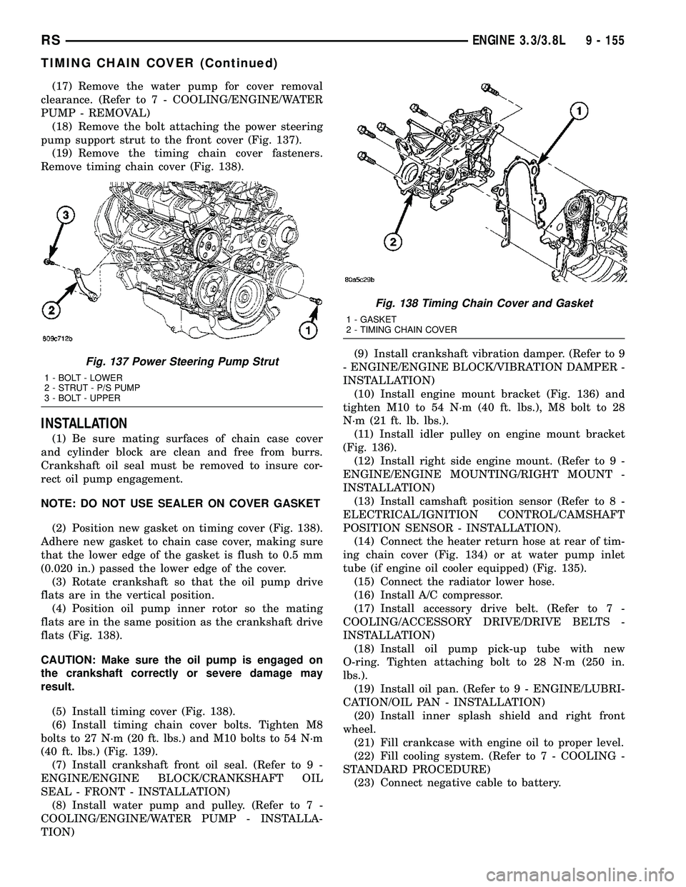
(18) Remove the bolt attaching the power steering
pump support strut to the front cover (Fig. 137).
(19) Remove the timing chain cover fasteners.
Remove timing chain cover (Fig. 138).
INSTALLATION
(1) Be sure mating surfaces of chain case cover
and cylinder block are clean and free from burrs.
Crankshaft oil seal must be removed to insure cor-
rect oil pump engagement.
NOTE: DO NOT USE SEALER ON COVER GASKET
(2) Position new gasket on timing cover (Fig. 138).
Adhere new gasket to chain case cover, making sure
that the lower edge of the gasket is flush to 0.5 mm
(0.020 in.) passed the lower edge of the cover.
(3) Rotate crankshaft so that the oil pump drive
flats are in the vertical position.
(4) Position oil pump inner rotor so the mating
flats are in the same position as the crankshaft drive
flats (Fig. 138).
CAUTION: Make sure the oil pump is engaged on
the crankshaft correctly or severe damage may
result.
(5) Install timing cover (Fig. 138).
(6) Install timing chain cover bolts. Tighten M8
bolts to 27 N´m (20 ft. lbs.) and M10 bolts to 54 N´m
(40 ft. lbs.) (Fig. 139).
(7) Install crankshaft front oil seal. (Refer to 9 -
ENGINE/ENGINE BLOCK/CRANKSHAFT OIL
SEAL - FRONT - INSTALLATION)
(8) Install water pump and pulley. (Refer to 7 -
COOLING/ENGINE/WATER PUMP - INSTALLA-
TION)(9) Install crankshaft vibration damper. (Refer to 9
- ENGINE/ENGINE BLOCK/VIBRATION DAMPER -
INSTALLATION)
(10) Install engine mount bracket (Fig. 136) and
tighten M10 to 54 N´m (40 ft. lbs.), M8 bolt to 28
N´m (21 ft. lb. lbs.).
(11) Install idler pulley on engine mount bracket
(Fig. 136).
(12) Install right side engine mount. (Refer to 9 -
ENGINE/ENGINE MOUNTING/RIGHT MOUNT -
INSTALLATION)
(13) Install camshaft position sensor (Refer to 8 -
ELECTRICAL/IGNITION CONTROL/CAMSHAFT
POSITION SENSOR - INSTALLATION).
(14) Connect the heater return hose at rear of tim-
ing chain cover (Fig. 134) or at water pump inlet
tube (if engine oil cooler equipped) (Fig. 135).
(15) Connect the radiator lower hose.
(16) Install A/C compressor.
(17) Install accessory drive belt. (Refer to 7 -
COOLING/ACCESSORY DRIVE/DRIVE BELTS -
INSTALLATION)
(18) Install oil pump pick-up tube with new
O-ring. Tighten attaching bolt to 28 N´m (250 in.
lbs.).
(19) Install oil pan. (Refer to 9 - ENGINE/LUBRI-
CATION/OIL PAN - INSTALLATION)
(20) Install inner splash shield and right front
wheel.
(21) Fill crankcase with engine oil to proper level.
(22) Fill cooling system. (Refer to 7 - COOLING -
STANDARD PROCEDURE)
(23) Connect negative cable to battery.
Fig. 137 Power Steering Pump Strut
1 - BOLT - LOWER
2 - STRUT - P/S PUMP
3 - BOLT - UPPER
Fig. 138 Timing Chain Cover and Gasket
1 - GASKET
2 - TIMING CHAIN COVER
RSENGINE 3.3/3.8L9 - 155
TIMING CHAIN COVER (Continued)
Page 1472 of 2585
CYLINDER-TO-WATER JACKET LEAKAGE TEST
WARNING: USE EXTREME CAUTION WHEN THE
ENGINE IS OPERATING WITH COOLANT PRES-
SURE CAP REMOVED.
VISUAL TEST METHOD
With the engine cool, remove the coolant pressure
cap. Start the engine and allow it to warm up until
thermostat opens.
If a large combustion/compression pressure leak
exists, bubbles will be visible in the coolant.
COOLING SYSTEM TESTER METHOD
WARNING: WITH COOLING SYSTEM TESTER IN
PLACE, PRESSURE WILL BUILD UP FAST. EXCES-
SIVE PRESSURE BUILT UP, BY CONTINUOUS
ENGINE OPERATION, MUST BE RELEASED TO A
SAFE PRESSURE POINT. NEVER PERMIT PRES-
SURE TO EXCEED 138 kPa (20 psi).
Install Cooling System Tester 7700 or equivalent to
pressure cap neck. Start the engine and observe the
tester's pressure gauge. If gauge pulsates with every
power stroke of a cylinder a combustion pressure
leak is evident.
CHEMICAL TEST METHOD
Combustion leaks into the cooling system can also
be checked by using Bloc-Chek Kit C-3685-A or
equivalent. Perform test following the procedures
supplied with the tool kit.
REMOVAL - CYLINDER HEAD
(1) Drain the cooling system. (Refer to 7 - COOL-
ING - STANDARD PROCEDURE)
(2) Disconnect negative cable from battery.
(3) Remove upper and lower intake manifolds.
(Refer to 9 - ENGINE/MANIFOLDS/INTAKE MANI-
FOLD - REMOVAL)
WARNING: INTAKE MANIFOLD GASKET IS MADE
OF VERY THIN METAL AND MAY CAUSE PER-
SONAL INJURY, HANDLE WITH CARE.
(4) Remove the cylinder head covers. (Refer to 9 -
ENGINE/CYLINDER HEAD/CYLINDER HEAD
COVER(S) - REMOVAL)
(5) Remove the spark plugs from cylinder head.
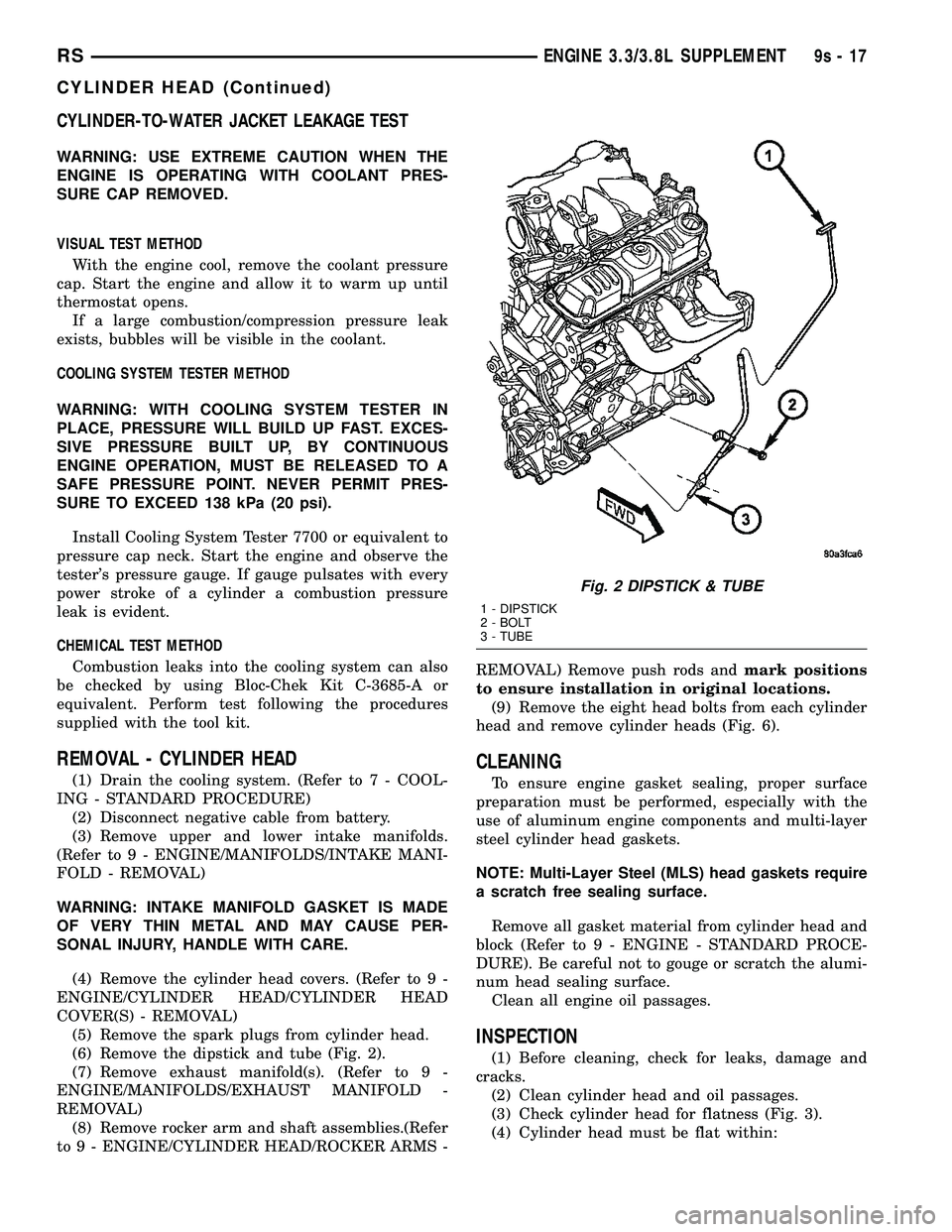
(6) Remove the dipstick and tube (Fig. 2).
(7) Remove exhaust manifold(s). (Refer to 9 -
ENGINE/MANIFOLDS/EXHAUST MANIFOLD -
REMOVAL)
(8) Remove rocker arm and shaft assemblies.(Refer
to 9 - ENGINE/CYLINDER HEAD/ROCKER ARMS -REMOVAL) Remove push rods andmark positions
to ensure installation in original locations.
(9) Remove the eight head bolts from each cylinder
head and remove cylinder heads (Fig. 6).
CLEANING
To ensure engine gasket sealing, proper surface
preparation must be performed, especially with the
use of aluminum engine components and multi-layer
steel cylinder head gaskets.
NOTE: Multi-Layer Steel (MLS) head gaskets require
a scratch free sealing surface.
Remove all gasket material from cylinder head and
block (Refer to 9 - ENGINE - STANDARD PROCE-
DURE). Be careful not to gouge or scratch the alumi-
num head sealing surface.
Clean all engine oil passages.
INSPECTION
(1) Before cleaning, check for leaks, damage and
cracks.
(2) Clean cylinder head and oil passages.
(3) Check cylinder head for flatness (Fig. 3).
(4) Cylinder head must be flat within:
Fig. 2 DIPSTICK & TUBE
1 - DIPSTICK
2 - BOLT
3 - TUBE
RSENGINE 3.3/3.8L SUPPLEMENT9s-17
CYLINDER HEAD (Continued)
Page 1486 of 2585
EXHAUST SYSTEM
TABLE OF CONTENTS
page page
EXHAUST SYSTEM
DESCRIPTION..........................1
DIAGNOSIS AND TESTING
DIAGNOSIS AND TESTING - EXCESSIVE
EXHAUST SYSTEM NOISE...............2
DIAGNOSIS AND TESTING - EXHAUST
SYSTEM RESTRICTION CHECK...........2
INSPECTION...........................3
ADJUSTMENTS.........................3
SPECIFICATIONS
TORQUE.............................3
SPECIAL TOOLS
EXHAUST SYSTEM.....................4
CATALYTIC CONVERTER
DESCRIPTION..........................4
OPERATION............................4
REMOVAL.............................5INSPECTION...........................5
INSTALLATION..........................6
CROSS-OVER PIPE - 3.3/3.8L
REMOVAL.............................6
INSTALLATION..........................6
HEAT SHIELDS
DESCRIPTION..........................6
OPERATION............................7
REMOVAL.............................7
INSTALLATION..........................7
MUFFLER
REMOVAL.............................7
INSTALLATION..........................7
RESONATOR
REMOVAL.............................9
INSTALLATION..........................9
EXHAUST SYSTEM
DESCRIPTION
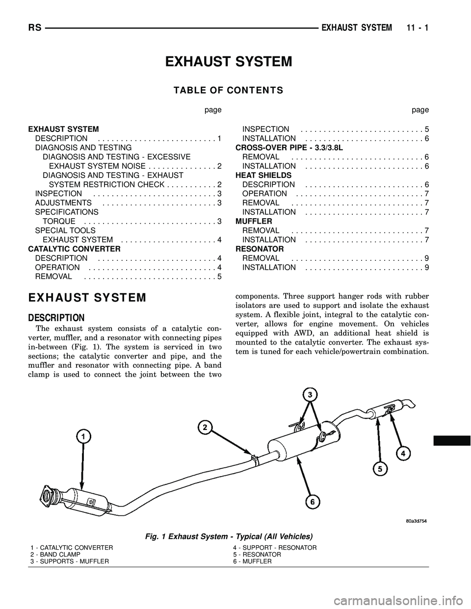
The exhaust system consists of a catalytic con-
verter, muffler, and a resonator with connecting pipes
in-between (Fig. 1). The system is serviced in two
sections; the catalytic converter and pipe, and the
muffler and resonator with connecting pipe. A band
clamp is used to connect the joint between the twocomponents. Three support hanger rods with rubber
isolators are used to support and isolate the exhaust
system. A flexible joint, integral to the catalytic con-
verter, allows for engine movement. On vehicles
equipped with AWD, an additional heat shield is
mounted to the catalytic converter. The exhaust sys-
tem is tuned for each vehicle/powertrain combination.
Fig. 1 Exhaust System - Typical (All Vehicles)
1 - CATALYTIC CONVERTER 4 - SUPPORT - RESONATOR
2 - BAND CLAMP 5 - RESONATOR
3 - SUPPORTS - MUFFLER 6 - MUFFLER
RSEXHAUST SYSTEM11-1
Page 1509 of 2585
FUEL DELIVERY
DESCRIPTION
The front wheel drive car uses a plastic fuel tank
located rear center of the vehicle.
The Fuel Delivery System consists of: the following
items:
²Electric fuel pump module
²Fuel filter
²Tubes/lines/hoses
²Fuel injectors
The in-tank fuel pump module contains the fuel
pump. The pump is serviced as part of the fuel pump
module. Refer to Fuel Pump Module.
The fuel filter is replaceable only as part of the
fuel pump module.
OPERATION
The fuel system provides fuel pressure by an
in-tank pump module. The Powertrain Control Mod-
ule (PCM) controls the operation of the fuel system
by providing battery voltage to the fuel pump
through the fuel pump relay. The PCM requires only
three inputs and a good ground to operate the fuel
pump relay. The three inputs are:
²Ignition voltage
²Crankshaft Position (CKP) sensor
²Camshaft Position (CMP) sensor
DIAGNOSIS AND TESTING - FUEL DELIVERY
SYSTEM
(Refer to Appropriate Diagnostic Information)
STANDARD PROCEDURE
STANDARD PROCEDURE - FUEL SYSTEM
PRESSURE RELEASE PROCEDURE
(1) Remove Fuel Pump relay from Power Distribu-
tion Center (PDC). For location of relay, refer to label
on underside of PDC cover.
(2) Start and run engine until it stalls.
(3) Attempt restarting engine until it will no
longer run.
(4) Turn ignition key to OFF position.
(5) Return fuel pump relay to PDC.
(6) One or more Diagnostic Trouble Codes (DTC's)
may have been stored in PCM memory due to fuel
pump relay removal. The DRB IIItscan tool must be
used to erase a DTC.
STANDARD PROCEDURE - DRAINING FUEL
TANK
Two different procedures may be used to drain fuel
tank (lowering tank or using DRBIIItscan tool).The quickest draining procedure involves lowering
the fuel tank.
WARNING: RELEASE FUEL SYSTEM PRESSURE
BEFORE SERVICING FUEL SYSTEM COMPONENTS.
SERVICE VEHICLES IN WELL VENTILATED AREAS
AND AVOID IGNITION SOURCES. NEVER SMOKE
WHILE SERVICING THE VEHICLE. THIS MAY
RESULT IN PERSONAL INJURY OR DEATH.
As an alternative procedure, the electric fuel pump
may be activated allowing tank to be drained at fuel
rail connection. Refer to DRBIIItscan tool for fuel
pump activation procedures. Before disconnecting
fuel line at fuel rail, release fuel pressure. Refer to
the Fuel System Pressure Release Procedure in this
group for procedures. Disconnect the fuel line at the
fuel rail and remove the plastic retainer from the
fuel rail. Take plastic retainer and install it back into
the fuel line from body. Check the O-ring and make
sure that it is in place and not damaged. Attach end
of special test hose tool number 6539 at fuel line con-
nection from the body line. Position opposite end of
this hose tool to an approved gasoline draining sta-
tion. Activate fuel pump and drain tank until empty.
When done remove the special test hose tool number
6539 from the body line. Remove the plastic retainer
from the special test hose tool number 6539 and rein-
stall it into the fuel line from the body. Check the
O-ring and make sure that it is in place and not
damaged. Install the fuel line to the fuel rail.
If electric fuel pump is not operating, tank must be
lowered for fuel draining. Refer to following proce-
dures.
(1) Remove fuel filler cap.
(2) Perform the Fuel System Pressure Release pro-
cedure.
(3) Disconnect negative cable from battery.
(4) Raise vehicle and support.
(5) Certain models are equipped with a separate
grounding wire (strap) connecting the fuel fill tube
assembly to the body. Disconnect wire by removing
screw.
(6) Open fuel fill door and remove screws mount-
ing fuel filler tube assembly to body. Do not discon-
nect rubber fuel fill or vent hoses from tank at this
time.
(7) Place a transmission jack under center of fuel
tank. Apply a slight amount of pressure to fuel tank
with transmission jack.
(8) Remove fuel tank mounting straps.
(9)Lower the tank just enough so that the
filler tube fitting is the highest point of the fuel
tank.
(10) Remove filler tube from fuel tank. Tank will
be drained through this fitting.
14 - 2 FUEL DELIVERYRS
Page 1525 of 2585
FUEL INJECTION
OPERATION
OPERATION - INJECTION SYSTEM
All engines used in this section have a sequential
Multi-Port Electronic Fuel Injection system. The MPI
system is computer regulated and provides precise
air/fuel ratios for all driving conditions. The Power-
train Control Module (PCM) operates the fuel injec-
tion system.
The PCM regulates:
²Ignition timing
²Air/fuel ratio
²Emission control devices
²Cooling fan
²Charging system
²Idle speed
²Vehicle speed control
Various sensors provide the inputs necessary for
the PCM to correctly operate these systems. In addi-
tion to the sensors, various switches also provide
inputs to the PCM.
The PCM can adapt its programming to meet
changing operating conditions.
Fuel is injected into the intake port above the
intake valve in precise metered amounts through
electrically operated injectors. The PCM fires the
injectors in a specific sequence. Under most operat-
ing conditions, the PCM maintains an air fuel ratio
of 14.7 parts air to 1 part fuel by constantly adjust-
ing injector pulse width. Injector pulse width is the
length of time the injector is open.
The PCM adjusts injector pulse width by opening
and closing the ground path to the injector. Engine
RPM (speed) and manifold absolute pressure (air
density) are theprimaryinputs that determine
injector pulse width.
OPERATION - MODES OF OPERATION
As input signals to the PCM change, the PCM
adjusts its response to output devices. For example,
the PCM must calculate a different injector pulse
width and ignition timing for idle than it does for
Wide Open Throttle (WOT). There are several differ-
ent modes of operation that determine how the PCM
responds to the various input signals.
There are two different areas of operation, OPEN
LOOP and CLOSED LOOP.
During OPEN LOOP modes the PCM receives
input signals and responds according to preset PCM
programming. Inputs from the upstream and down-
stream heated oxygen sensors are not monitored dur-
ing OPEN LOOP modes, except for heated oxygensensor diagnostics (they are checked for shorted con-
ditions at all times).
During CLOSED LOOP modes the PCM monitors
the inputs from the upstream and downstream
heated oxygen sensors. The upstream heated oxygen
sensor input tells the PCM if the calculated injector
pulse width resulted in the ideal air-fuel ratio of 14.7
to one. By monitoring the exhaust oxygen content
through the upstream heated oxygen sensor, the
PCM can fine tune injector pulse width. Fine tuning
injector pulse width allows the PCM to achieve opti-
mum fuel economy combined with low emissions.
For the PCM to enter CLOSED LOOP operation,
the following must occur:
(1) Engine coolant temperature must be over 35ÉF.
²If the coolant is over 35ÉF the PCM will wait 38
seconds.
²If the coolant is over 50ÉF the PCM will wait 15
seconds.
²If the coolant is over 167ÉF the PCM will wait 3
seconds.
(2) For other temperatures the PCM will interpo-
late the correct waiting time.
(3) O2 sensor must read either greater than 0.745
volts or less than 0.29 volt.
(4) The multi-port fuel injection systems has the
following modes of operation:
²Ignition switch ON (Zero RPM)
²Engine start-up
²Engine warm-up
²Cruise
²Idle
²Acceleration
²Deceleration
²Wide Open Throttle
²Ignition switch OFF
(5) The engine start-up (crank), engine warm-up,
deceleration with fuel shutoff and wide open throttle
modes are OPEN LOOP modes. Under most operat-
ing conditions, the acceleration, deceleration (with
A/C on), idle and cruise modes,with the engine at
operating temperatureare CLOSED LOOP modes.
IGNITION SWITCH ON (ZERO RPM) MODE
When the ignition switch activates the fuel injec-
tion system, the following actions occur:
²The PCM monitors the engine coolant tempera-
ture sensor and throttle position sensor input. The
PCM determines basic fuel injector pulse width from
this input.
²The PCM determines atmospheric air pressure
from the MAP sensor input to modify injector pulse
width.
When the key is in the ON position and the engine
is not running (zero rpm), the Auto Shutdown (ASD)
and fuel pump relays de-energize after approximately
14 - 18 FUEL INJECTIONRS
Page 1528 of 2585
opposite preset limit or switch point. The process
then repeats itself in the opposite direction.
Short term fuel correction will keep increasing or
decreasing injector pulse-width based upon the
upstream O2 Sensor input. The maximum range of
authority for short term memory is 25% (+/-) of base
pulse-width. Short term is violated and is lost when
ignition is turned OFF.
Long Term
The second fuel correction program is the long
term adaptive memory. In order to maintain correct
emission throughout all operating ranges of the
engine, a cell structure based on engine rpm and load
(MAP) is used.
Ther number of cells varies upon the driving con-
ditions. Two cells are used only during idle, based
upon TPS and Park/Neutral switch inputs. There
may be two other cells used for deceleration, based
on TPS, engine rpm, and vehicle speed. The other
twelve cells represent a manifold pressure and an
rpm range. Six of the cells are high rpm and the
other six are low rpm. Each of these cells has a spe-
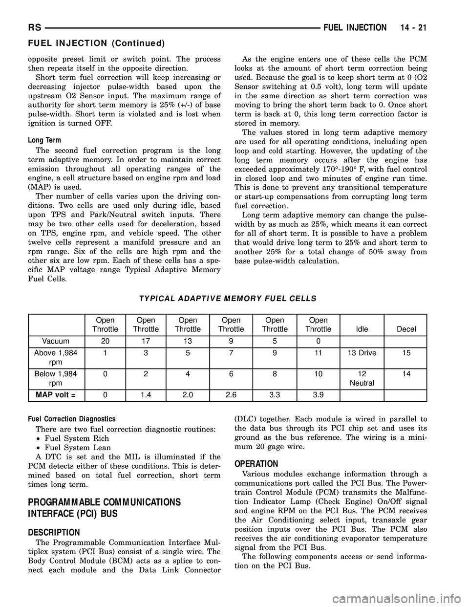
cific MAP voltage range Typical Adaptive Memory
Fuel Cells.As the engine enters one of these cells the PCM
looks at the amount of short term correction being
used. Because the goal is to keep short term at 0 (O2
Sensor switching at 0.5 volt), long term will update
in the same direction as short term correction was
moving to bring the short term back to 0. Once short
term is back at 0, this long term correction factor is
stored in memory.
The values stored in long term adaptive memory
are used for all operating conditions, including open
loop and cold starting. However, the updating of the
long term memory occurs after the engine has
exceeded approximately 170É-190É F, with fuel control
in closed loop and two minutes of engine run time.
This is done to prevent any transitional temperature
or start-up compensations from corrupting long term
fuel correction.
Long term adaptive memory can change the pulse-
width by as much as 25%, which means it can correct
for all of short term. It is possible to have a problem
that would drive long term to 25% and short term to
another 25% for a total change of 50% away from
base pulse-width calculation.
TYPICAL ADAPTIVE MEMORY FUEL CELLS
Open
ThrottleOpen
ThrottleOpen
ThrottleOpen
ThrottleOpen
ThrottleOpen
Throttle Idle Decel
Vacuum 20 17 13 9 5 0
Above 1,984
rpm1 3 5 7 9 11 13 Drive 15
Below 1,984
rpm02 4 6 8 1012
Neutral14
MAP volt =0 1.4 2.0 2.6 3.3 3.9
Fuel Correction Diagnostics
There are two fuel correction diagnostic routines:
²Fuel System Rich
²Fuel System Lean
A DTC is set and the MIL is illuminated if the
PCM detects either of these conditions. This is deter-
mined based on total fuel correction, short term
times long term.
PROGRAMMABLE COMMUNICATIONS
INTERFACE (PCI) BUS
DESCRIPTION
The Programmable Communication Interface Mul-
tiplex system (PCI Bus) consist of a single wire. The
Body Control Module (BCM) acts as a splice to con-
nect each module and the Data Link Connector(DLC) together. Each module is wired in parallel to
the data bus through its PCI chip set and uses its
ground as the bus reference. The wiring is a mini-
mum 20 gage wire.
OPERATION
Various modules exchange information through a
communications port called the PCI Bus. The Power-
train Control Module (PCM) transmits the Malfunc-
tion Indicator Lamp (Check Engine) On/Off signal
and engine RPM on the PCI Bus. The PCM receives
the Air Conditioning select input, transaxle gear
position inputs over the PCI Bus. The PCM also
receives the air conditioning evaporator temperature
signal from the PCI Bus.
The following components access or send informa-
tion on the PCI Bus.
RSFUEL INJECTION14-21
FUEL INJECTION (Continued)
Page 1529 of 2585
²Instrument Panel
²Body Control Module
²Air Bag System Diagnostic Module
²Full ATC Display Head (if equipped)
²ABS Module
²Transmission Control Module
²Powertrain Control Module
²Travel Module
²SKIMSYSTEM DIAGNOSIS
OPERATION
The PCM can test many of its own input and out-
put circuits. If the PCM senses a fault in a major
system, the PCM stores a Diagnostic Trouble Code
(DTC) in memory.
For DTC information see On-Board Diagnostics
(Refer to 8 - ELECTRICAL/ELECTRONIC CON-
TROL MODULES/POWERTRAIN CONTROL MOD-
ULE - DESCRIPTION) .
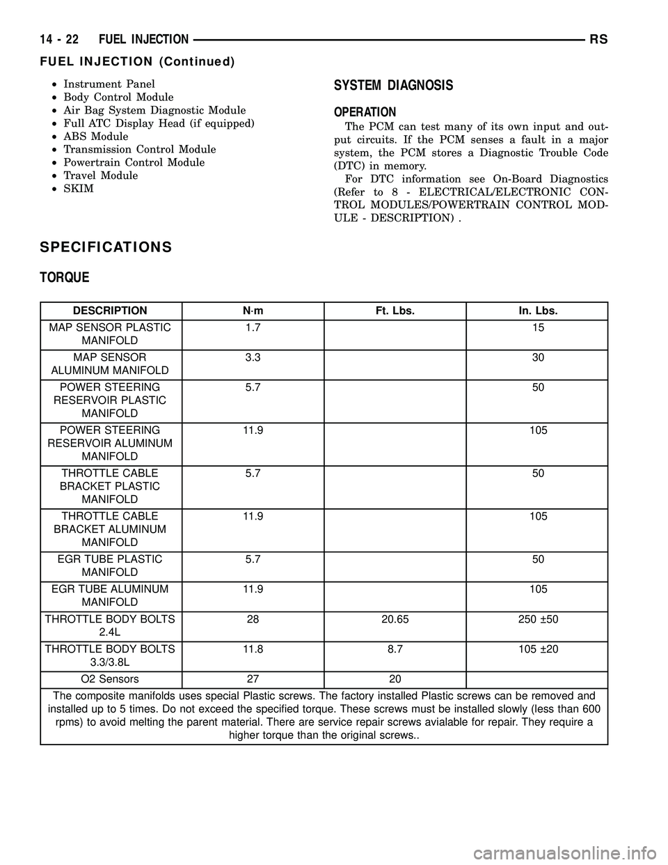
SPECIFICATIONS
TORQUE
DESCRIPTION N´m Ft. Lbs. In. Lbs.
MAP SENSOR PLASTIC
MANIFOLD1.7 15
MAP SENSOR
ALUMINUM MANIFOLD3.3 30
POWER STEERING
RESERVOIR PLASTIC
MANIFOLD5.7 50
POWER STEERING
RESERVOIR ALUMINUM
MANIFOLD11.9 105
THROTTLE CABLE
BRACKET PLASTIC
MANIFOLD5.7 50
THROTTLE CABLE
BRACKET ALUMINUM
MANIFOLD11.9 105
EGR TUBE PLASTIC
MANIFOLD5.7 50
EGR TUBE ALUMINUM
MANIFOLD11.9 105
THROTTLE BODY BOLTS
2.4L28 20.65 250 50
THROTTLE BODY BOLTS
3.3/3.8L11.8 8.7 105 20
O2 Sensors 27 20
The composite manifolds uses special Plastic screws. The factory installed Plastic screws can be removed and
installed up to 5 times. Do not exceed the specified torque. These screws must be installed slowly (less than 600
rpms) to avoid melting the parent material. There are service repair screws avialable for repair. They require a
higher torque than the original screws..
14 - 22 FUEL INJECTIONRS
FUEL INJECTION (Continued)