2004 CHRYSLER VOYAGER air condition
[x] Cancel search: air conditionPage 2403 of 2585
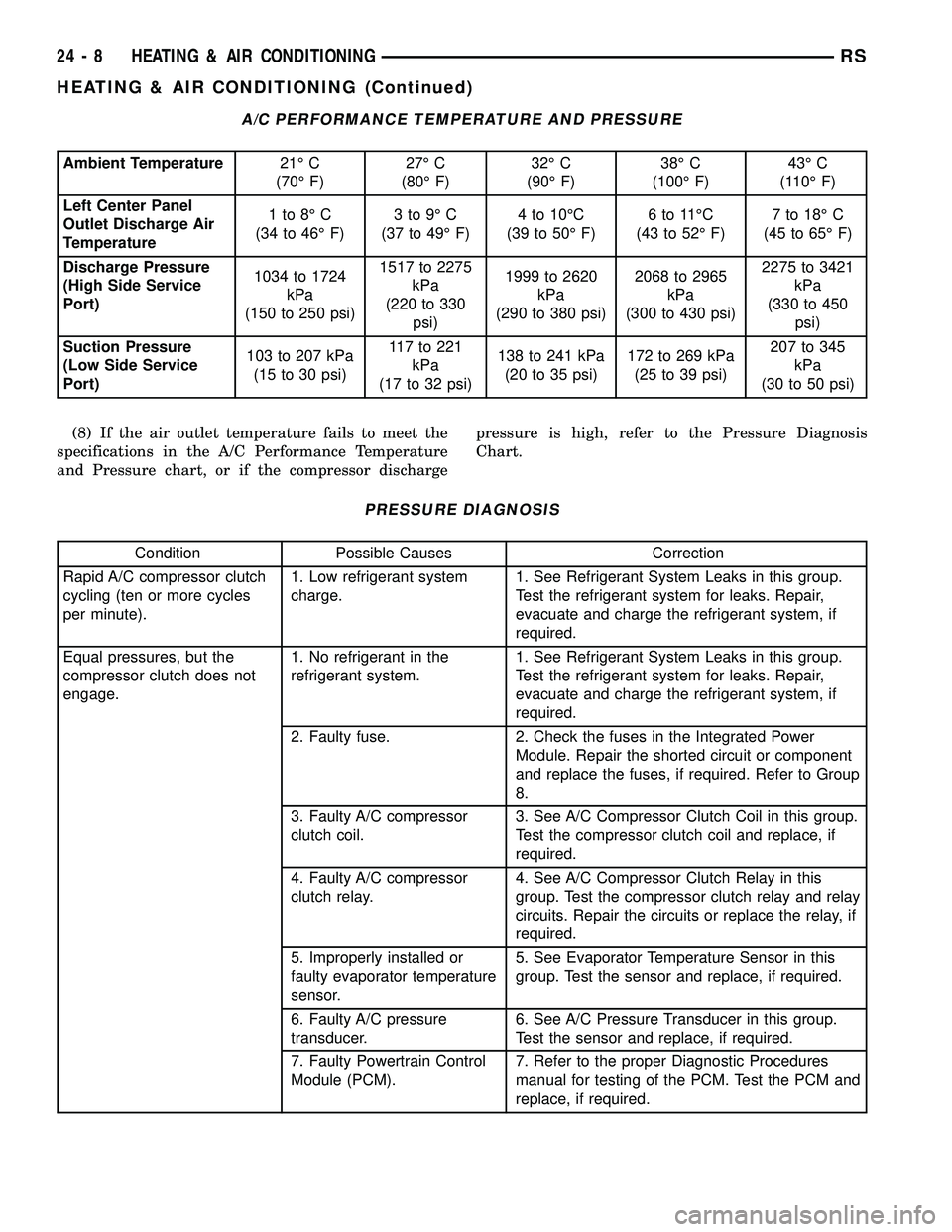
A/C PERFORMANCE TEMPERATURE AND PRESSURE
Ambient Temperature21É C
(70É F)27É C
(80É F)32É C
(90É F)38É C
(100É F)43É C
(110É F)
Left Center Panel
Outlet Discharge Air
Temperature1to8ÉC
(34 to 46É F)3to9ÉC
(37 to 49É F)4 to 10ÉC
(39 to 50É F)6to11ÉC
(43 to 52É F)7 to 18É C
(45 to 65É F)
Discharge Pressure
(High Side Service
Port)1034 to 1724
kPa
(150 to 250 psi)1517 to 2275
kPa
(220 to 330
psi)1999 to 2620
kPa
(290 to 380 psi)2068 to 2965
kPa
(300 to 430 psi)2275 to 3421
kPa
(330 to 450
psi)
Suction Pressure
(Low Side Service
Port)103 to 207 kPa
(15 to 30 psi)117to221
kPa
(17 to 32 psi)138 to 241 kPa
(20 to 35 psi)172 to 269 kPa
(25 to 39 psi)207 to 345
kPa
(30 to 50 psi)
(8) If the air outlet temperature fails to meet the
specifications in the A/C Performance Temperature
and Pressure chart, or if the compressor dischargepressure is high, refer to the Pressure Diagnosis
Chart.
PRESSURE DIAGNOSIS
Condition Possible Causes Correction
Rapid A/C compressor clutch
cycling (ten or more cycles
per minute).1. Low refrigerant system
charge.1. See Refrigerant System Leaks in this group.
Test the refrigerant system for leaks. Repair,
evacuate and charge the refrigerant system, if
required.
Equal pressures, but the
compressor clutch does not
engage.1. No refrigerant in the
refrigerant system.1. See Refrigerant System Leaks in this group.
Test the refrigerant system for leaks. Repair,
evacuate and charge the refrigerant system, if
required.
2. Faulty fuse. 2. Check the fuses in the Integrated Power
Module. Repair the shorted circuit or component
and replace the fuses, if required. Refer to Group
8.
3. Faulty A/C compressor
clutch coil.3. See A/C Compressor Clutch Coil in this group.
Test the compressor clutch coil and replace, if
required.
4. Faulty A/C compressor
clutch relay.4. See A/C Compressor Clutch Relay in this
group. Test the compressor clutch relay and relay
circuits. Repair the circuits or replace the relay, if
required.
5. Improperly installed or
faulty evaporator temperature
sensor.5. See Evaporator Temperature Sensor in this
group. Test the sensor and replace, if required.
6. Faulty A/C pressure
transducer.6. See A/C Pressure Transducer in this group.
Test the sensor and replace, if required.
7. Faulty Powertrain Control
Module (PCM).7. Refer to the proper Diagnostic Procedures
manual for testing of the PCM. Test the PCM and
replace, if required.
24 - 8 HEATING & AIR CONDITIONINGRS
HEATING & AIR CONDITIONING (Continued)
Page 2404 of 2585
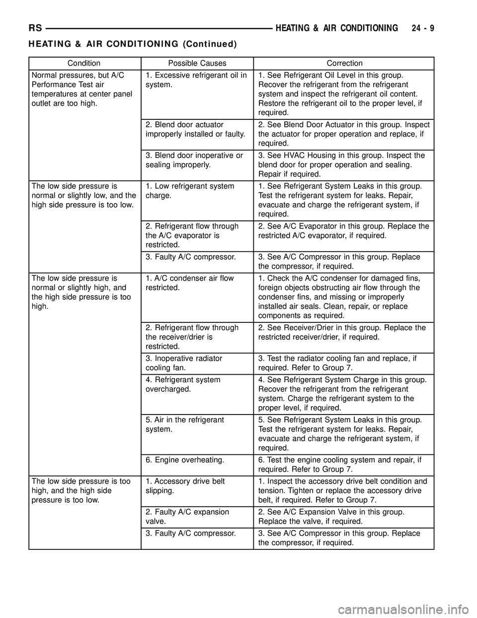
Condition Possible Causes Correction
Normal pressures, but A/C
Performance Test air
temperatures at center panel
outlet are too high.1. Excessive refrigerant oil in
system.1. See Refrigerant Oil Level in this group.
Recover the refrigerant from the refrigerant
system and inspect the refrigerant oil content.
Restore the refrigerant oil to the proper level, if
required.
2. Blend door actuator
improperly installed or faulty.2. See Blend Door Actuator in this group. Inspect
the actuator for proper operation and replace, if
required.
3. Blend door inoperative or
sealing improperly.3. See HVAC Housing in this group. Inspect the
blend door for proper operation and sealing.
Repair if required.
The low side pressure is
normal or slightly low, and the
high side pressure is too low.1. Low refrigerant system
charge.1. See Refrigerant System Leaks in this group.
Test the refrigerant system for leaks. Repair,
evacuate and charge the refrigerant system, if
required.
2. Refrigerant flow through
the A/C evaporator is
restricted.2. See A/C Evaporator in this group. Replace the
restricted A/C evaporator, if required.
3. Faulty A/C compressor. 3. See A/C Compressor in this group. Replace
the compressor, if required.
The low side pressure is
normal or slightly high, and
the high side pressure is too
high.1. A/C condenser air flow
restricted.1. Check the A/C condenser for damaged fins,
foreign objects obstructing air flow through the
condenser fins, and missing or improperly
installed air seals. Clean, repair, or replace
components as required.
2. Refrigerant flow through
the receiver/drier is
restricted.2. See Receiver/Drier in this group. Replace the
restricted receiver/drier, if required.
3. Inoperative radiator
cooling fan.3. Test the radiator cooling fan and replace, if
required. Refer to Group 7.
4. Refrigerant system
overcharged.4. See Refrigerant System Charge in this group.
Recover the refrigerant from the refrigerant
system. Charge the refrigerant system to the
proper level, if required.
5. Air in the refrigerant
system.5. See Refrigerant System Leaks in this group.
Test the refrigerant system for leaks. Repair,
evacuate and charge the refrigerant system, if
required.
6. Engine overheating. 6. Test the engine cooling system and repair, if
required. Refer to Group 7.
The low side pressure is too
high, and the high side
pressure is too low.1. Accessory drive belt
slipping.1. Inspect the accessory drive belt condition and
tension. Tighten or replace the accessory drive
belt, if required. Refer to Group 7.
2. Faulty A/C expansion
valve.2. See A/C Expansion Valve in this group.
Replace the valve, if required.
3. Faulty A/C compressor. 3. See A/C Compressor in this group. Replace
the compressor, if required.
RSHEATING & AIR CONDITIONING24-9
HEATING & AIR CONDITIONING (Continued)
Page 2405 of 2585
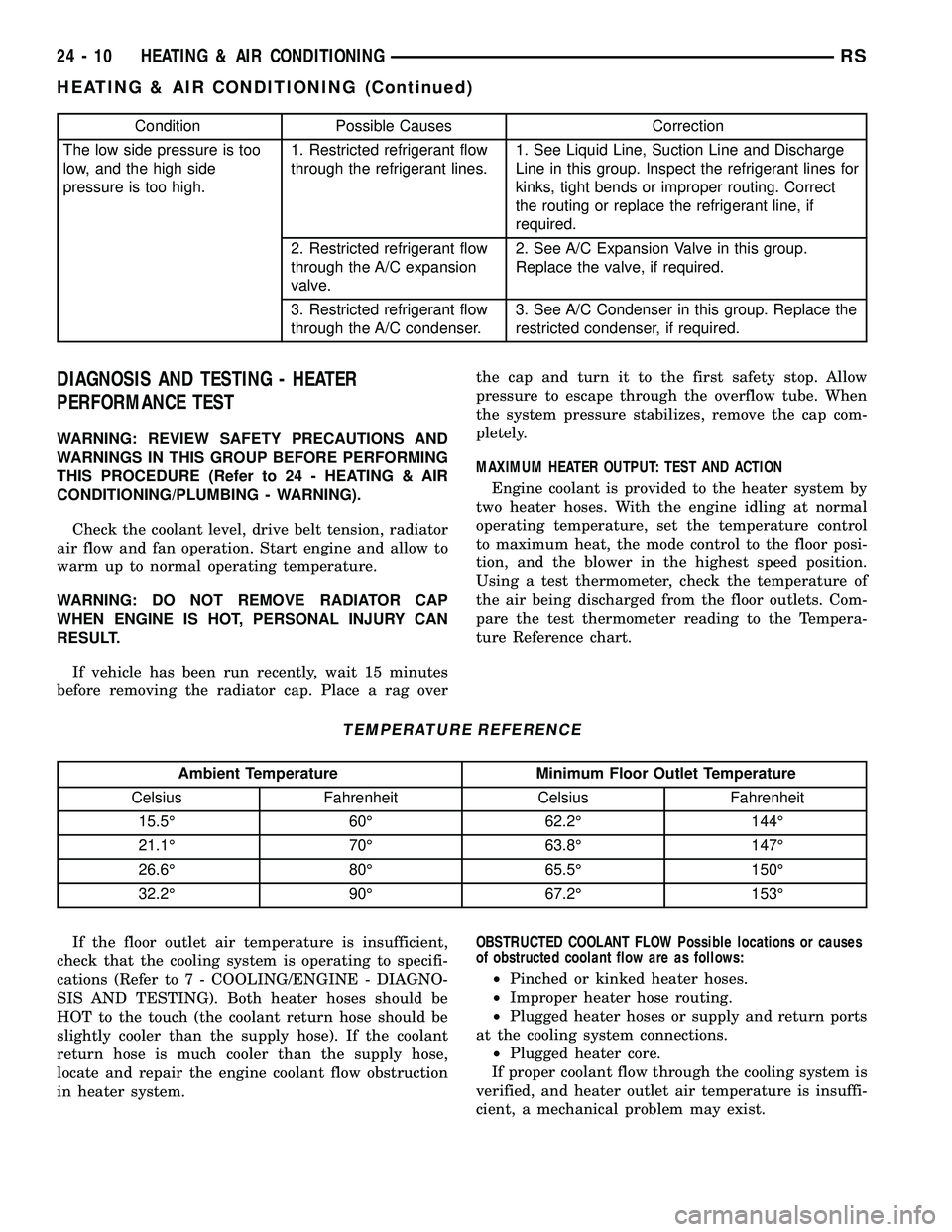
Condition Possible Causes Correction
The low side pressure is too
low, and the high side
pressure is too high.1. Restricted refrigerant flow
through the refrigerant lines.1. See Liquid Line, Suction Line and Discharge
Line in this group. Inspect the refrigerant lines for
kinks, tight bends or improper routing. Correct
the routing or replace the refrigerant line, if
required.
2. Restricted refrigerant flow
through the A/C expansion
valve.2. See A/C Expansion Valve in this group.
Replace the valve, if required.
3. Restricted refrigerant flow
through the A/C condenser.3. See A/C Condenser in this group. Replace the
restricted condenser, if required.
DIAGNOSIS AND TESTING - HEATER
PERFORMANCE TEST
WARNING: REVIEW SAFETY PRECAUTIONS AND
WARNINGS IN THIS GROUP BEFORE PERFORMING
THIS PROCEDURE (Refer to 24 - HEATING & AIR
CONDITIONING/PLUMBING - WARNING).
Check the coolant level, drive belt tension, radiator
air flow and fan operation. Start engine and allow to
warm up to normal operating temperature.
WARNING: DO NOT REMOVE RADIATOR CAP
WHEN ENGINE IS HOT, PERSONAL INJURY CAN
RESULT.
If vehicle has been run recently, wait 15 minutes
before removing the radiator cap. Place a rag overthe cap and turn it to the first safety stop. Allow
pressure to escape through the overflow tube. When
the system pressure stabilizes, remove the cap com-
pletely.
MAXIMUM HEATER OUTPUT: TEST AND ACTION
Engine coolant is provided to the heater system by
two heater hoses. With the engine idling at normal
operating temperature, set the temperature control
to maximum heat, the mode control to the floor posi-
tion, and the blower in the highest speed position.
Using a test thermometer, check the temperature of
the air being discharged from the floor outlets. Com-
pare the test thermometer reading to the Tempera-
ture Reference chart.
TEMPERATURE REFERENCE
Ambient Temperature Minimum Floor Outlet Temperature
Celsius Fahrenheit Celsius Fahrenheit
15.5É 60É 62.2É 144É
21.1É 70É 63.8É 147É
26.6É 80É 65.5É 150É
32.2É 90É 67.2É 153É
If the floor outlet air temperature is insufficient,
check that the cooling system is operating to specifi-
cations (Refer to 7 - COOLING/ENGINE - DIAGNO-
SIS AND TESTING). Both heater hoses should be
HOT to the touch (the coolant return hose should be
slightly cooler than the supply hose). If the coolant
return hose is much cooler than the supply hose,
locate and repair the engine coolant flow obstruction
in heater system.OBSTRUCTED COOLANT FLOW Possible locations or causes
of obstructed coolant flow are as follows:
²Pinched or kinked heater hoses.
²Improper heater hose routing.
²Plugged heater hoses or supply and return ports
at the cooling system connections.
²Plugged heater core.
If proper coolant flow through the cooling system is
verified, and heater outlet air temperature is insuffi-
cient, a mechanical problem may exist.
24 - 10 HEATING & AIR CONDITIONINGRS
HEATING & AIR CONDITIONING (Continued)
Page 2406 of 2585
MECHANICAL PROBLEMS
Possible causes of insufficient heat due to mechan-
ical problems are as follows:
²Obstructed cowl air intake.
²Obstructed heater system outlets.
²Blend door not functioning properly.
TEMPERATURE CONTROL
If the heater outlet air temperature cannot be
adjusted with the temperature control knob on the
A/C-heater control panel, the following could require
service:
²Blend door binding.²Faulty blend door actuator.
²Faulty A/C-heater control.
²Faulty related wiring harness or connectors.
²Improper engine coolant temperature.
SPECIFICATIONS
A/C SYSTEM
The R-134a refrigerant system charge capacity for
this vehicle can be found on the underhood Specifica-
tion Label.
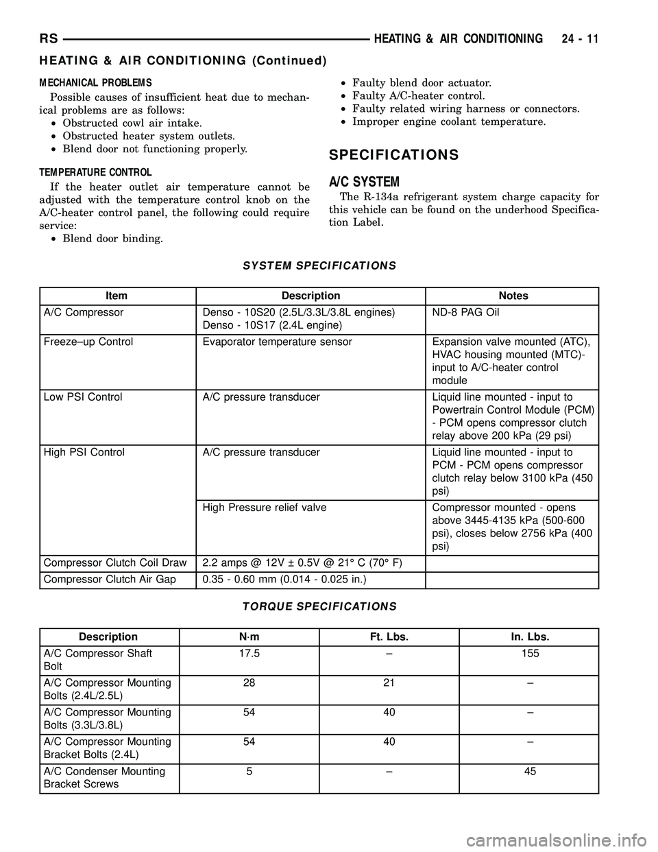
SYSTEM SPECIFICATIONS
Item Description Notes
A/C Compressor Denso - 10S20 (2.5L/3.3L/3.8L engines)
Denso - 10S17 (2.4L engine)ND-8 PAG Oil
Freeze±up Control Evaporator temperature sensor Expansion valve mounted (ATC),
HVAC housing mounted (MTC)-
input to A/C-heater control
module
Low PSI Control A/C pressure transducer Liquid line mounted - input to
Powertrain Control Module (PCM)
- PCM opens compressor clutch
relay above 200 kPa (29 psi)
High PSI Control A/C pressure transducer Liquid line mounted - input to
PCM - PCM opens compressor
clutch relay below 3100 kPa (450
psi)
High Pressure relief valve Compressor mounted - opens
above 3445-4135 kPa (500-600
psi), closes below 2756 kPa (400
psi)
Compressor Clutch Coil Draw 2.2 amps @ 12V 0.5V @ 21É C (70É F)
Compressor Clutch Air Gap 0.35 - 0.60 mm (0.014 - 0.025 in.)
TORQUE SPECIFICATIONS
Description N´m Ft. Lbs. In. Lbs.
A/C Compressor Shaft
Bolt17.5 ± 155
A/C Compressor Mounting
Bolts (2.4L/2.5L)28 21 ±
A/C Compressor Mounting
Bolts (3.3L/3.8L)54 40 ±
A/C Compressor Mounting
Bracket Bolts (2.4L)54 40 ±
A/C Condenser Mounting
Bracket Screws5±45
RSHEATING & AIR CONDITIONING24-11
HEATING & AIR CONDITIONING (Continued)
Page 2407 of 2585
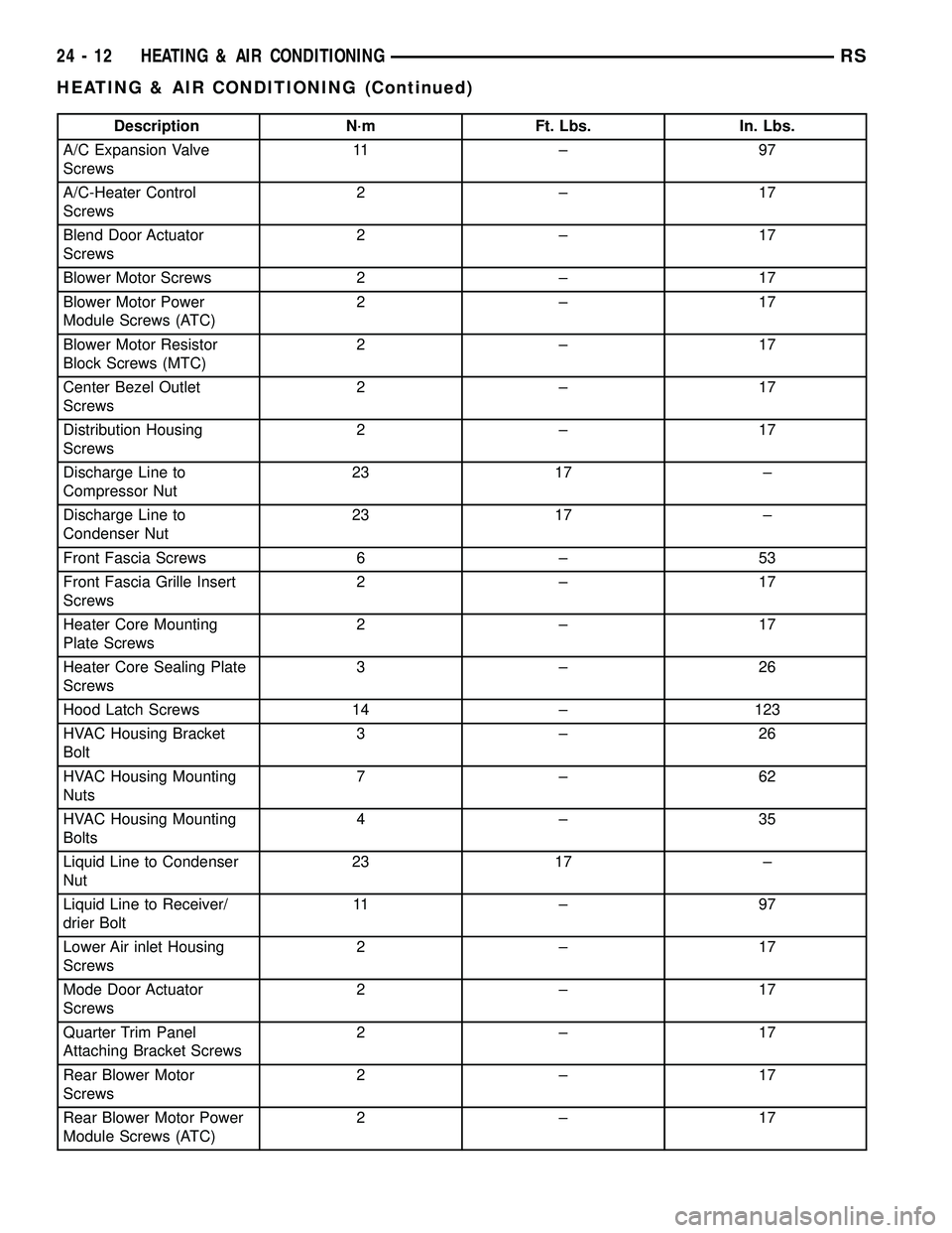
Description N´m Ft. Lbs. In. Lbs.
A/C Expansion Valve
Screws11 ± 9 7
A/C-Heater Control
Screws2±17
Blend Door Actuator
Screws2±17
Blower Motor Screws 2 ± 17
Blower Motor Power
Module Screws (ATC)2±17
Blower Motor Resistor
Block Screws (MTC)2±17
Center Bezel Outlet
Screws2±17
Distribution Housing
Screws2±17
Discharge Line to
Compressor Nut23 17 ±
Discharge Line to
Condenser Nut23 17 ±
Front Fascia Screws 6 ± 53
Front Fascia Grille Insert
Screws2±17
Heater Core Mounting
Plate Screws2±17
Heater Core Sealing Plate
Screws3±26
Hood Latch Screws 14 ± 123
HVAC Housing Bracket
Bolt3±26
HVAC Housing Mounting
Nuts7±62
HVAC Housing Mounting
Bolts4±35
Liquid Line to Condenser
Nut23 17 ±
Liquid Line to Receiver/
drier Bolt11 ± 9 7
Lower Air inlet Housing
Screws2±17
Mode Door Actuator
Screws2±17
Quarter Trim Panel
Attaching Bracket Screws2±17
Rear Blower Motor
Screws2±17
Rear Blower Motor Power
Module Screws (ATC)2±17
24 - 12 HEATING & AIR CONDITIONINGRS
HEATING & AIR CONDITIONING (Continued)
Page 2408 of 2585
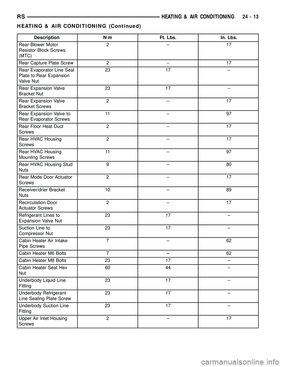
Description N´m Ft. Lbs. In. Lbs.
Rear Blower Motor
Resistor Block Screws
(MTC)2±17
Rear Capture Plate Screw 2 ± 17
Rear Evaporator Line Seal
Plate to Rear Expansion
Valve Nut23 17 ±
Rear Expansion Valve
Bracket Nut23 17 ±
Rear Expansion Valve
Bracket Screws2±17
Rear Expansion Valve to
Rear Evaporator Screws11 ± 9 7
Rear Floor Heat Duct
Screws2±17
Rear HVAC Housing
Screws2±17
Rear HVAC Housing
Mounting Screws11 ± 9 7
Rear HVAC Housing Stud
Nuts9±80
Rear Mode Door Actuator
Screws2±17
Receiver/drier Bracket
Nuts10 ± 89
Recirculation Door
Actuator Screws2±17
Refrigerant Lines to
Expansion Valve Nut23 17 ±
Suction Line to
Compressor Nut23 17 ±
Cabin Heater Air Intake
Pipe Screws7±62
Cabin Heater M6 Bolts 7 ± 62
Cabin Heater M8 Bolts 23 17 ±
Cabin Heater Seat Hex
Nut60 44 ±
Underbody Liquid Line
Fitting23 17 ±
Underbody Refrigerant
Line Sealing Plate Screw23 17 ±
Underbody Suction Line
Fitting23 17 ±
Upper Air Inlet Housing
Screws2±17
RSHEATING & AIR CONDITIONING24-13
HEATING & AIR CONDITIONING (Continued)
Page 2410 of 2585
A/C COMPRESSOR CLUTCH/
COIL
DESCRIPTION
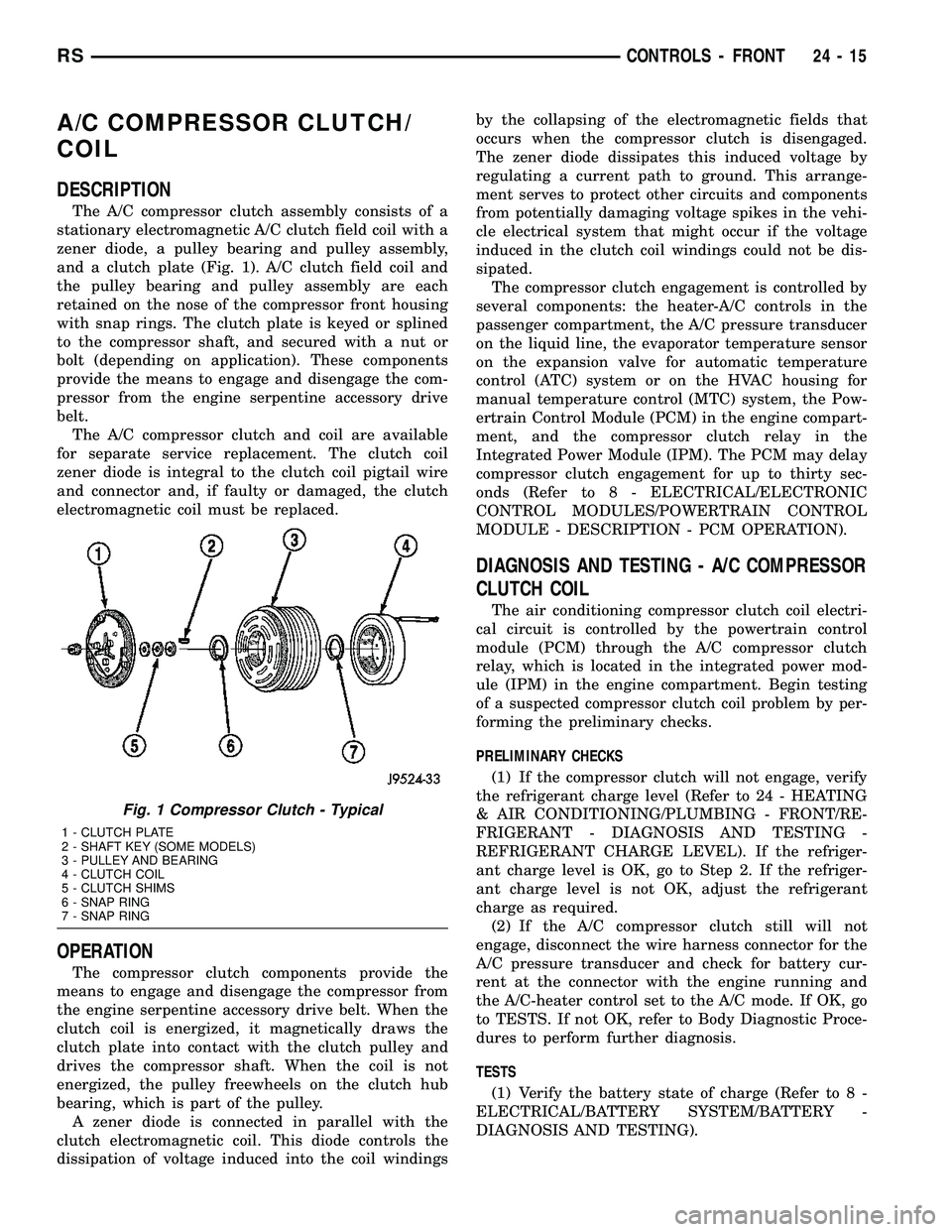
The A/C compressor clutch assembly consists of a
stationary electromagnetic A/C clutch field coil with a
zener diode, a pulley bearing and pulley assembly,
and a clutch plate (Fig. 1). A/C clutch field coil and
the pulley bearing and pulley assembly are each
retained on the nose of the compressor front housing
with snap rings. The clutch plate is keyed or splined
to the compressor shaft, and secured with a nut or
bolt (depending on application). These components
provide the means to engage and disengage the com-
pressor from the engine serpentine accessory drive
belt.
The A/C compressor clutch and coil are available
for separate service replacement. The clutch coil
zener diode is integral to the clutch coil pigtail wire
and connector and, if faulty or damaged, the clutch
electromagnetic coil must be replaced.
OPERATION
The compressor clutch components provide the
means to engage and disengage the compressor from
the engine serpentine accessory drive belt. When the
clutch coil is energized, it magnetically draws the
clutch plate into contact with the clutch pulley and
drives the compressor shaft. When the coil is not
energized, the pulley freewheels on the clutch hub
bearing, which is part of the pulley.
A zener diode is connected in parallel with the
clutch electromagnetic coil. This diode controls the
dissipation of voltage induced into the coil windingsby the collapsing of the electromagnetic fields that
occurs when the compressor clutch is disengaged.
The zener diode dissipates this induced voltage by
regulating a current path to ground. This arrange-
ment serves to protect other circuits and components
from potentially damaging voltage spikes in the vehi-
cle electrical system that might occur if the voltage
induced in the clutch coil windings could not be dis-
sipated.
The compressor clutch engagement is controlled by
several components: the heater-A/C controls in the
passenger compartment, the A/C pressure transducer
on the liquid line, the evaporator temperature sensor
on the expansion valve for automatic temperature
control (ATC) system or on the HVAC housing for
manual temperature control (MTC) system, the Pow-
ertrain Control Module (PCM) in the engine compart-
ment, and the compressor clutch relay in the
Integrated Power Module (IPM). The PCM may delay
compressor clutch engagement for up to thirty sec-
onds (Refer to 8 - ELECTRICAL/ELECTRONIC
CONTROL MODULES/POWERTRAIN CONTROL
MODULE - DESCRIPTION - PCM OPERATION).
DIAGNOSIS AND TESTING - A/C COMPRESSOR
CLUTCH COIL
The air conditioning compressor clutch coil electri-
cal circuit is controlled by the powertrain control
module (PCM) through the A/C compressor clutch
relay, which is located in the integrated power mod-
ule (IPM) in the engine compartment. Begin testing
of a suspected compressor clutch coil problem by per-
forming the preliminary checks.
PRELIMINARY CHECKS
(1) If the compressor clutch will not engage, verify
the refrigerant charge level (Refer to 24 - HEATING
& AIR CONDITIONING/PLUMBING - FRONT/RE-
FRIGERANT - DIAGNOSIS AND TESTING -
REFRIGERANT CHARGE LEVEL). If the refriger-
ant charge level is OK, go to Step 2. If the refriger-
ant charge level is not OK, adjust the refrigerant
charge as required.
(2) If the A/C compressor clutch still will not
engage, disconnect the wire harness connector for the
A/C pressure transducer and check for battery cur-
rent at the connector with the engine running and
the A/C-heater control set to the A/C mode. If OK, go
to TESTS. If not OK, refer to Body Diagnostic Proce-
dures to perform further diagnosis.
TESTS
(1) Verify the battery state of charge (Refer to 8 -
ELECTRICAL/BATTERY SYSTEM/BATTERY -
DIAGNOSIS AND TESTING).
Fig. 1 Compressor Clutch - Typical
1 - CLUTCH PLATE
2 - SHAFT KEY (SOME MODELS)
3 - PULLEY AND BEARING
4 - CLUTCH COIL
5 - CLUTCH SHIMS
6 - SNAP RING
7 - SNAP RING
RSCONTROLS - FRONT24-15
Page 2417 of 2585

erence signal and a sensor ground to the transducer,
then monitors the output voltage of the transducer
on a sensor return circuit to determine refrigerant
pressure. The PCM is programmed to respond to this
and other sensor inputs by controlling the operation
of the A/C compressor clutch and the radiator cooling
fan to help optimize air conditioning system perfor-
mance and to protect the system components from
damage. The A/C pressure transducer input to the
PCM will also prevent the A/C compressor clutch
from engaging when ambient temperatures are below
about 4.5É C (40É F) due to the pressure/temperature
relationship of the refrigerant. The Schrader-type
valve in the liquid line fitting permits the A/C pres-
sure transducer to be removed or installed without
disturbing the refrigerant in the system. The A/C
pressure transducer is diagnosed using a DRBIIIt
scan tool. Refer to Body Diagnostic Procedures.
DIAGNOSIS AND TESTING - A/C PRESSURE
TRANSDUCER
The A/C pressure transducer is tested using a
DRBIIItscan tool. Refer to the appropriate diagnos-
tic information. Before testing the A/C pressure
transducer, be certain that the transducer wire har-
ness connection is clean of corrosion and properly
connected. For the A/C to operate, an A/C pressure
transducer voltage reading between 0.451 and 4.519
volts is required. Voltages outside this range indicate
a low or high refrigerant system pressure condition
to the powertrain control module (PCM). The PCM is
programmed to respond to a low or high refrigerant
system pressure by suppressing operation of the A/C
compressor. Refer to the A/C Pressure Transducer
Voltage chart for the possible conditions indicated by
the transducer voltage reading.
A/C PRESSURE TRANSDUCER VOLTAGE
Voltage Possible Indication
0.0 1. No sensor supply voltage from
PCM.
2. Shorted sensor circuit.
3. Faulty transducer.
0.150 TO 0.450 1. Ambient temperature below 10É
C (50É F).
2. Low refrigerant system pressure.
0.451 TO 4.519 1. Normal refrigerant system
pressure.
4.520 TO 4.850 1. High refrigerant system pressure.
5.0 1. Open sensor circuit.
2. Faulty transducer.
REMOVAL
NOTE: Note: It is not necessary to discharge the
refrigerant system to replace the A/C pressure
transducer.
(1) Disconnect and isolate the battery negative
cable.
(2) Disconnect the wire harness connector from the
A/C pressure transducer (Fig. 10).
(3) Remove the A/C pressure transducer from the
fitting on the liquid line.
(4) Remove the O-ring seal from the A/C pressure
transducer fitting and discard.
INSTALLATION
NOTE: Replace the O-ring seal before installing the
A/C pressure transducer.
(1) Lubricate a new rubber O-ring seal with clean
refrigerant oil and install it on the A/C pressure
transducer fitting. Use only the specified O-rings as
they are made of a special material for the R-134a
system. Use only refrigerant oil of the type recom-
mended for the A/C compressor in the vehicle.
(2) Install and tighten the A/C pressure transducer
onto the fitting onto the liquid line fitting.
(3) Connect the wire harness connector to the A/C
pressure transducer.
(4) Reconnect the battery negative cable.
Fig. 10 A/C Pressure Transducer - Typical
1 - RIGHT FRONT STRUT TOWER
2 - WIRE HARNESS CONNECTOR
3 - A/C PRESSURE TRANSDUCER
4 - WIPER MODULE DRAIN TUBE
5 - HIGH SIDE SERVICE PORT
6 - LIQUID LINE
24 - 22 CONTROLS - FRONTRS
A/C PRESSURE TRANSDUCER (Continued)