2004 CHRYSLER VOYAGER warning
[x] Cancel search: warningPage 1571 of 2585
GEAR
TABLE OF CONTENTS
page page
GEAR
DESCRIPTION.........................26
OPERATION...........................27
WARNING
WARNINGS AND CAUTIONS.............27
REMOVAL
REMOVAL - LHD GEAR.................27
REMOVAL - RHD GEAR................31INSTALLATION
INSTALLATION - LHD GEAR.............32
INSTALLATION - RHD GEAR.............33
SPECIAL TOOLS
POWER STEERING GEAR..............34
OUTER TIE ROD
REMOVAL.............................34
INSTALLATION.........................34
GEAR
DESCRIPTION
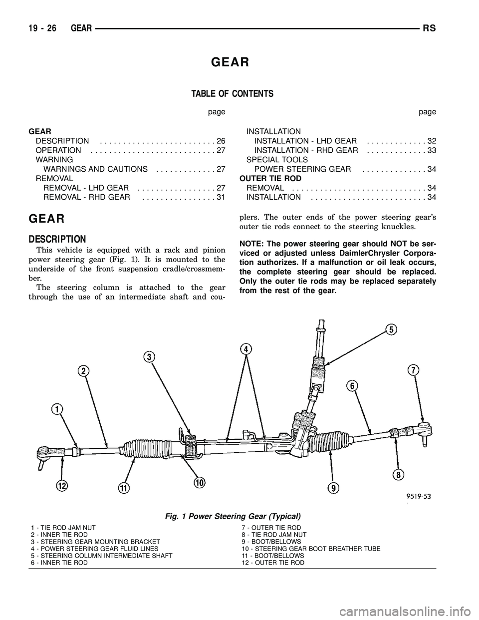
This vehicle is equipped with a rack and pinion
power steering gear (Fig. 1). It is mounted to the
underside of the front suspension cradle/crossmem-
ber.
The steering column is attached to the gear
through the use of an intermediate shaft and cou-plers. The outer ends of the power steering gear's
outer tie rods connect to the steering knuckles.
NOTE: The power steering gear should NOT be ser-
viced or adjusted unless DaimlerChrysler Corpora-
tion authorizes. If a malfunction or oil leak occurs,
the complete steering gear should be replaced.
Only the outer tie rods may be replaced separately
from the rest of the gear.
Fig. 1 Power Steering Gear (Typical)
1 - TIE ROD JAM NUT
2 - INNER TIE ROD
3 - STEERING GEAR MOUNTING BRACKET
4 - POWER STEERING GEAR FLUID LINES
5 - STEERING COLUMN INTERMEDIATE SHAFT
6 - INNER TIE ROD7 - OUTER TIE ROD
8 - TIE ROD JAM NUT
9 - BOOT/BELLOWS
10 - STEERING GEAR BOOT BREATHER TUBE
11 - BOOT/BELLOWS
12 - OUTER TIE ROD
19 - 26 GEARRS
Page 1572 of 2585
OPERATION
Turning of the steering wheel is converted into lin-
ear (side-to-side) travel through the meshing of the
helical pinion teeth with the rack teeth in the steer-
ing gear. This travel pushes and pulls the tie rods to
change the direction of the vehicle's front wheels.
Power assist steering provided by the power steer-
ing pump is controlled by an open center, rotary type
control valve which directs oil from the pump to
either side of the integral rack piston upon demand.
Road feel is controlled by the diameter of a torsion
bar which initially steers the vehicle. As required
steering effort increases, as in a turn, the torsion bar
twists, causing relative rotary motion between the
rotary valve body and the valve spool. This move-
ment directs oil behind the integral rack piston
which, in turn, builds hydraulic pressure and assists
in the turning effort.
Manual steering control of the vehicle can be main-
tained if power steering assist is lost. However,
under this condition, steering effort is significantly
increased.
WARNING
WARNINGS AND CAUTIONS
WARNING: POWER STEERING FLUID, ENGINE
PARTS AND EXHAUST SYSTEM MAY BE
EXTREMELY HOT IF ENGINE HAS BEEN RUNNING.
DO NOT START ENGINE WITH ANY LOOSE OR DIS-
CONNECTED HOSES. DO NOT ALLOW HOSES TO
TOUCH HOT EXHAUST MANIFOLD OR CATALYST.
WARNING: FLUID LEVEL SHOULD BE CHECKED
WITH THE ENGINE OFF TO PREVENT PERSONAL
INJURY FROM MOVING PARTS.
CAUTION: When the system is open, cap all open
ends of the hoses, power steering pump fittings or
power steering gear ports to prevent entry of for-
eign material into the components.
REMOVAL
REMOVAL - LHD GEAR
(1) Remove cap from power steering fluid reser-
voir.
(2) Using a siphon pump, remove as much fluid as
possible from the power steering fluid reservoir.Use
care not to damage the filter mesh below the
fluid surface.
CAUTION: Locking the steering column in the
straight-ahead position will prevent the clockspring
from being accidentally over-extended when the
steering column is disconnected from the interme-
diate steering coupler.
(3) Position the steering wheel in the STRAIGHT-
AHEAD position. Lock the steering wheel in place
using a steering wheel holding tool.
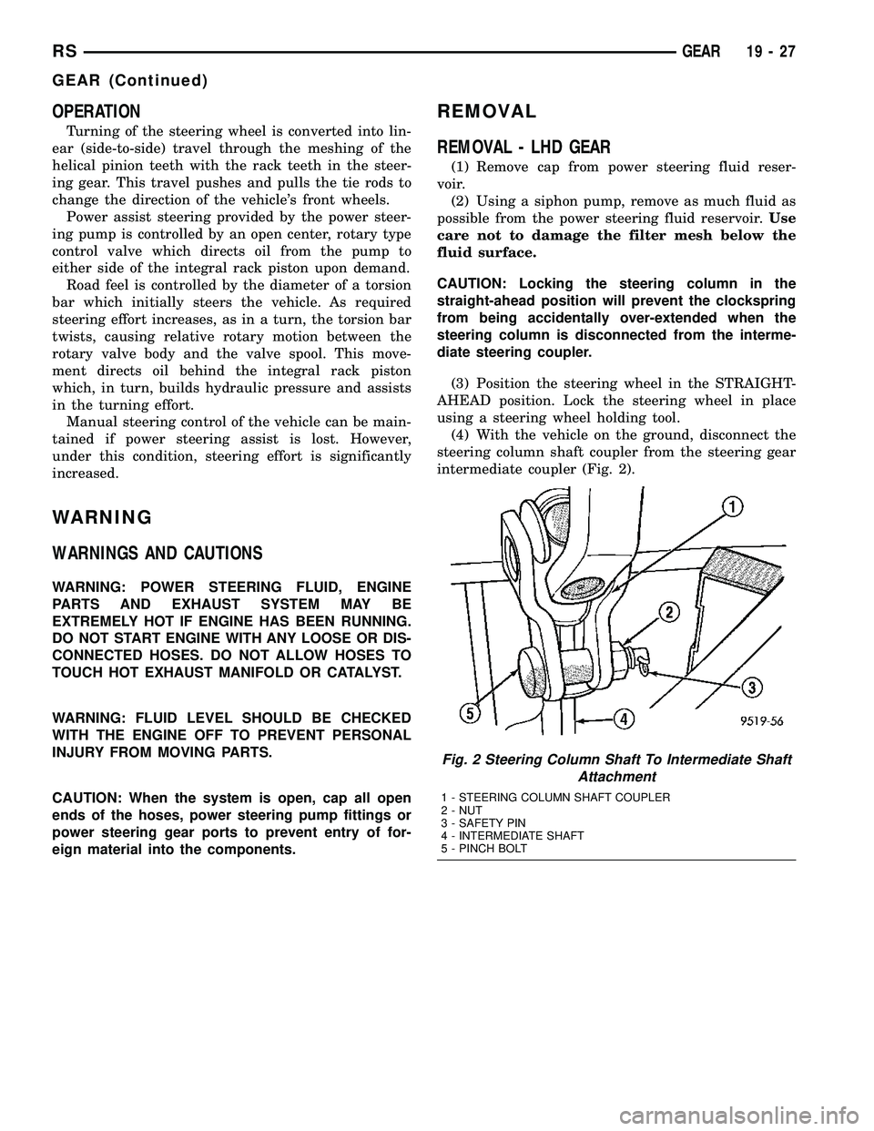
(4) With the vehicle on the ground, disconnect the
steering column shaft coupler from the steering gear
intermediate coupler (Fig. 2).
Fig. 2 Steering Column Shaft To Intermediate Shaft
Attachment
1 - STEERING COLUMN SHAFT COUPLER
2 - NUT
3 - SAFETY PIN
4 - INTERMEDIATE SHAFT
5 - PINCH BOLT
RSGEAR19-27
GEAR (Continued)
Page 1581 of 2585
PUMP
TABLE OF CONTENTS
page page
PUMP
DESCRIPTION
DESCRIPTION - PUMP (2.4L/3.3L/3.8L
ENGINE)............................36
DESCRIPTION - PUMP (2.5L DIESEL)......36
OPERATION...........................37
WARNING.............................37
CAUTION.............................37
STANDARD PROCEDURE - POWER
STEERING PUMP INITIAL OPERATION.....37
REMOVAL
REMOVAL - PUMP (2.4L ENGINE).........38
REMOVAL - PUMP (3.3L/3.8L ENGINE).....40
REMOVAL - PUMP (2.5L DIESEL).........40
DISASSEMBLY - PUMP (PULLEY)..........41
ASSEMBLY - PUMP (PULLEY).............41
INSTALLATION
INSTALLATION - PUMP (2.4L ENGINE).....42
INSTALLATION - PUMP (3.3L/3.8L ENGINE) . 43
INSTALLATION - PUMP (2.5L DIESEL)......43
SPECIAL TOOLS
POWER STEERING PUMP..............43
FLUID
STANDARD PROCEDURE - POWER
STEERING FLUID LEVEL CHECKING......44
FLUID COOLER
DESCRIPTION.........................44
OPERATION...........................44
REMOVAL.............................44
INSTALLATION.........................45
HOSE - POWER STEERING PRESSURE
REMOVAL
REMOVAL - 2.4L ENGINE...............45REMOVAL - 3.3L/3.8L ENGINE...........45
INSTALLATION
INSTALLATION - 2.4L ENGINE...........46
INSTALLATION - 3.3L/3.8L ENGINE........47
HOSE - POWER STEERING RETURN
REMOVAL
REMOVAL - 2.4L ENGINE...............48
REMOVAL - 3.3L/3.8L ENGINE...........48
INSTALLATION
INSTALLATION - 2.4L ENGINE...........49
INSTALLATION - 3.3L/3.8L ENGINE........49
HOSE - POWER STEERING SUPPLY
REMOVAL
REMOVAL - 2.4L ENGINE...............50
REMOVAL - 3.3L/3.8L ENGINE...........50
INSTALLATION
INSTALLATION - 2.4L ENGINE...........50
INSTALLATION - 3.3L/3.8L ENGINE........50
RESERVOIR - POWER STEERING FLUID
DESCRIPTION
DESCRIPTION - 2.4L/3.3L/3.8L ENGINE....51
DESCRIPTION - 2.5L DIESEL............51
OPERATION...........................51
REMOVAL
REMOVAL - 2.4L ENGINE...............51
REMOVAL - 3.3L/3.8L ENGINE...........51
REMOVAL - 2.5L DIESEL................51
INSTALLATION
INSTALLATION - 2.4L ENGINE...........52
INSTALLATION - 3.3L/3.8L ENGINE........52
INSTALLATION - 2.5L DIESEL............52
PUMP
DESCRIPTION
DESCRIPTION - PUMP (2.4L/3.3L/3.8L
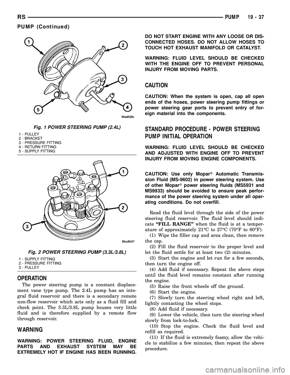
ENGINE)
Hydraulic pressure for the operation of the power
steering gear is provided by a belt driven power
steering pump. The power steering pump is mounted
on the back side of the engine on all engine applica-
tions. The pumps are different depending on the
engine option. The pump for the 2.4L engine is madeout of cast iron and steel (Fig. 1). The pump used on
the 3.3L/3.8L engine is made of aluminum (Fig. 2).
The pump for the 3.3L/3.8L engine does not have a
return fitting as the pump for the 2.4L engine does.
The power steering return hose on the 3.3L/3.8L
engine goes to the reservoir instead of the pump.DESCRIPTION - PUMP (2.5L DIESEL)
Hydraulic pressure for the operation of the power
steering gear is provided by a belt driven power
steering pump. The power steering pump is mounted
front lower right corner of the engine (Fig. 13).
The pump has a supply fitting for fluid coming
from the reservoir and a pressure port for exiting
fluid that is headed for the steering gear.
19 - 36 PUMPRS
Page 1582 of 2585
OPERATION
The power steering pump is a constant displace-
ment vane type pump. The 2.4L pump has an inte-
gral fluid reservoir and there is a secondary remote
non-flow reservoir which acts only as a fluid fill and
check point. The 3.3L/3.8L pump houses very little
fluid and is therefore supplied by a remote flow
through reservoir.
WARNING
WARNING: POWER STEERING FLUID, ENGINE
PARTS AND EXHAUST SYSTEM MAY BE
EXTREMELY HOT IF ENGINE HAS BEEN RUNNING.DO NOT START ENGINE WITH ANY LOOSE OR DIS-
CONNECTED HOSES. DO NOT ALLOW HOSES TO
TOUCH HOT EXHAUST MANIFOLD OR CATALYST.
WARNING: FLUID LEVEL SHOULD BE CHECKED
WITH THE ENGINE OFF TO PREVENT PERSONAL
INJURY FROM MOVING PARTS.
CAUTION
CAUTION: When the system is open, cap all open
ends of the hoses, power steering pump fittings or
power steering gear ports to prevent entry of for-
eign material into the components.
STANDARD PROCEDURE - POWER STEERING
PUMP INITIAL OPERATION
WARNING: FLUID LEVEL SHOULD BE CHECKED
AND ADJUSTED WITH ENGINE OFF TO PREVENT
INJURY FROM MOVING ENGINE COMPONENTS.
CAUTION: Use only MoparTAutomatic Transmis-
sion Fluid (MS-9602) in power steering system. Use
of other MoparTpower steering fluids (MS5931 and
MS9933) should be avoided to ensure peak perfor-
mance of the power steering system under all oper-
ating conditions. Do not overfill.
Read the fluid level through the side of the power
steering fluid reservoir. The fluid level should indi-
cateªFILL RANGEºwhen the fluid is at a temper-
ature of approximately 21ÉC to 27ÉC (70ÉF to 80ÉF).
(1) Wipe the filler cap and area clean, then remove
the cap.
(2) Fill the fluid reservoir to the proper level and
let the fluid settle for at least two (2) minutes.
(3) Start the engine and let run for a few seconds,
then turn the engine off.
(4) Add fluid if necessary. Repeat the above steps
until the fluid level remains constant after running
the engine.
(5) Raise the front wheels off the ground.
(6) Start the engine.
(7) Slowly turn the steering wheel right and left,
lightly contacting the wheel stops.
(8) Add fluid if necessary.
(9) Lower the vehicle, then turn the steering wheel
slowly from lock-to-lock.
(10) Stop the engine. Check the fluid level and
refill as required.
(11) If the fluid is extremely foamy, allow the vehi-
cle to stabilize a few minutes, then repeat the above
procedure.
Fig. 1 POWER STEERING PUMP (2.4L)
1 - PULLEY
2 - BRACKET
3 - PRESSURE FITTING
4 - RETURN FITTING
5 - SUPPLY FITTING
Fig. 2 POWER STEERING PUMP (3.3L/3.8L)
1 - SUPPLY FITTING
2 - PRESSURE FITTING
3 - PULLEY
RSPUMP19-37
PUMP (Continued)
Page 1589 of 2585
FLUID
STANDARD PROCEDURE - POWER STEERING
FLUID LEVEL CHECKING
WARNING: FLUID LEVEL SHOULD BE CHECKED
WITH THE ENGINE OFF TO PREVENT INJURY
FROM MOVING PARTS AND TO ENSURE ACCU-
RATE FLUID LEVEL READING.
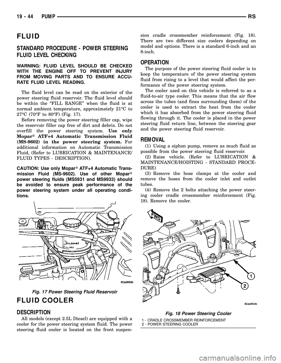
The fluid level can be read on the exterior of the
power steering fluid reservoir. The fluid level should
be within the ªFILL RANGEº when the fluid is at
normal ambient temperature, approximately 21ÉC to
27ÉC (70ÉF to 80ÉF) (Fig. 17).
Before removing the power steering filler cap, wipe
the reservoir filler cap free of dirt and debris. Do not
overfill the power steering system.Use only
MopartATF+4 Automatic Transmission Fluid
(MS-9602) in the power steering system.For
additional information on Automatic Transmission
Fluid, (Refer to LUBRICATION & MAINTENANCE/
FLUID TYPES - DESCRIPTION).
CAUTION: Use only MoparTATF+4 Automatic Trans-
mission Fluid (MS-9602). Use of other MoparT
power steering fluids (MS5931 and MS9933) should
be avoided to ensure peak performance of the
power steering system under all operating condi-
tions.
FLUID COOLER
DESCRIPTION
All models (except 2.5L Diesel) are equipped with a
cooler for the power steering system fluid. The power
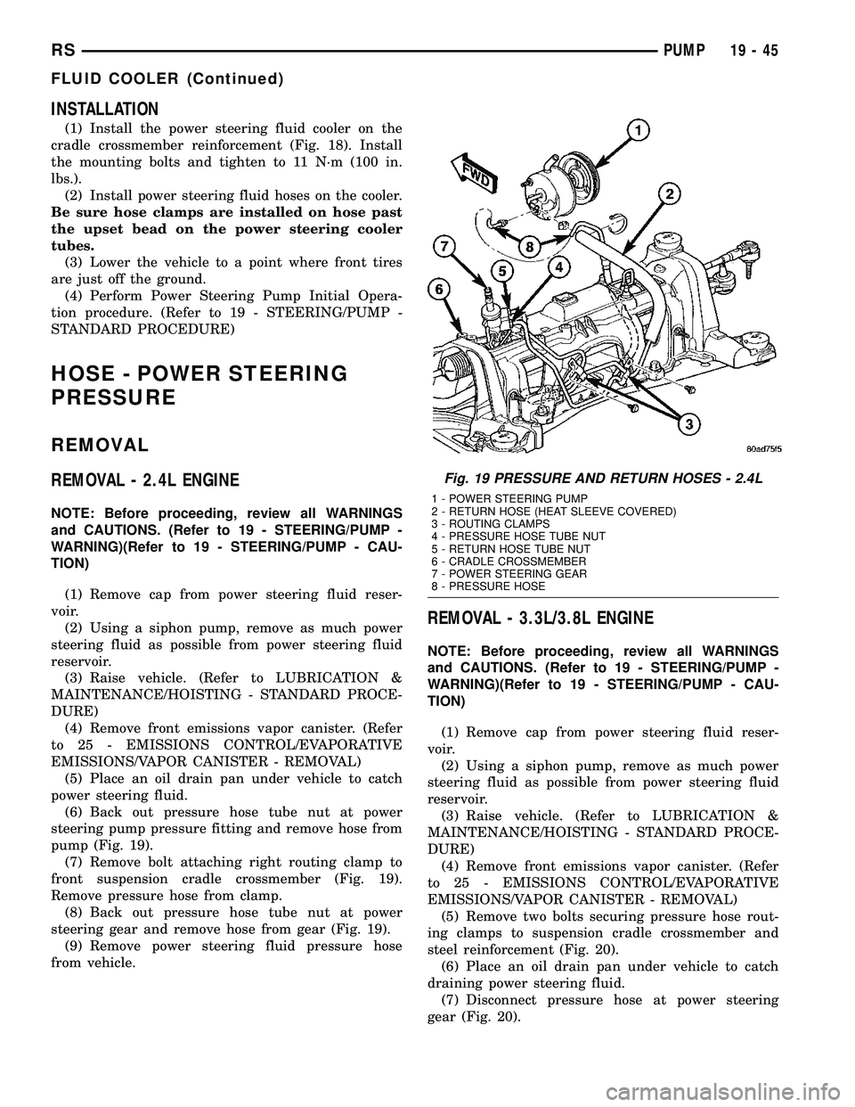
steering fluid cooler is located on the front suspen-sion cradle crossmember reinforcement (Fig. 18).
There are two different size coolers depending on
model and options. There is a standard 6-inch and an
8-inch.
OPERATION
The purpose of the power steering fluid cooler is to
keep the temperature of the power steering system
fluid from rising to a level that would affect the per-
formance of the power steering system.
The cooler used on this vehicle is referred to as a
fluid-to-air type cooler. This means that the air flow
across the tubes (and fines surrounding them) of the
cooler is used to extract the heat from the cooler
which it has absorbed from the power steering fluid
flowing through it. The cooler is placed in the power
steering fluid return line, between the steering gear
and the power steering fluid reservoir.
REMOVAL
(1) Using a siphon pump, remove as much fluid as
possible from the power steering fluid reservoir.
(2) Raise vehicle. (Refer to LUBRICATION &
MAINTENANCE/HOISTING - STANDARD PROCE-
DURE)
(3) Remove the hose clamps at the cooler and
remove the hoses from the cooler inlet and outlet
tubes.
(4) Remove the 2 bolts attaching the power steer-
ing cooler cradle crossmember reinforcement (Fig.
18). Remove the cooler.
Fig. 17 Power Steering Fluid Reservoir
Fig. 18 Power Steering Cooler
1 - CRADLE CROSSMEMBER REINFORCEMENT
2 - POWER STEERING COOLER
19 - 44 PUMPRS
Page 1590 of 2585
INSTALLATION
(1) Install the power steering fluid cooler on the
cradle crossmember reinforcement (Fig. 18). Install
the mounting bolts and tighten to 11 N´m (100 in.
lbs.).
(2) Install power steering fluid hoses on the cooler.
Be sure hose clamps are installed on hose past
the upset bead on the power steering cooler
tubes.
(3) Lower the vehicle to a point where front tires
are just off the ground.
(4) Perform Power Steering Pump Initial Opera-
tion procedure. (Refer to 19 - STEERING/PUMP -
STANDARD PROCEDURE)
HOSE - POWER STEERING
PRESSURE
REMOVAL
REMOVAL - 2.4L ENGINE
NOTE: Before proceeding, review all WARNINGS
and CAUTIONS. (Refer to 19 - STEERING/PUMP -
WARNING)(Refer to 19 - STEERING/PUMP - CAU-
TION)
(1) Remove cap from power steering fluid reser-
voir.
(2) Using a siphon pump, remove as much power
steering fluid as possible from power steering fluid
reservoir.
(3) Raise vehicle. (Refer to LUBRICATION &
MAINTENANCE/HOISTING - STANDARD PROCE-
DURE)
(4) Remove front emissions vapor canister. (Refer
to 25 - EMISSIONS CONTROL/EVAPORATIVE
EMISSIONS/VAPOR CANISTER - REMOVAL)
(5) Place an oil drain pan under vehicle to catch
power steering fluid.
(6) Back out pressure hose tube nut at power
steering pump pressure fitting and remove hose from
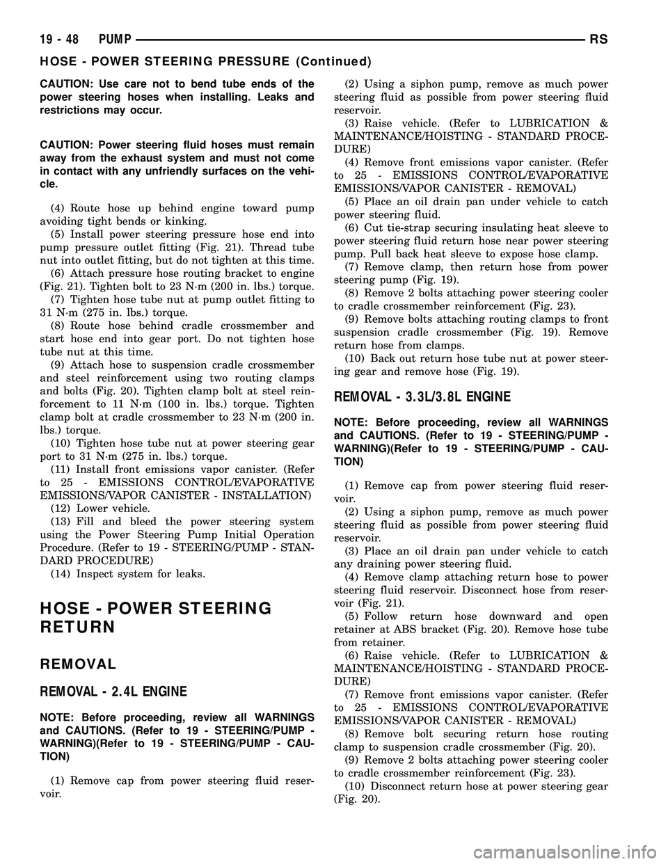
pump (Fig. 19).
(7) Remove bolt attaching right routing clamp to
front suspension cradle crossmember (Fig. 19).
Remove pressure hose from clamp.
(8) Back out pressure hose tube nut at power
steering gear and remove hose from gear (Fig. 19).
(9) Remove power steering fluid pressure hose
from vehicle.
REMOVAL - 3.3L/3.8L ENGINE
NOTE: Before proceeding, review all WARNINGS
and CAUTIONS. (Refer to 19 - STEERING/PUMP -
WARNING)(Refer to 19 - STEERING/PUMP - CAU-
TION)
(1) Remove cap from power steering fluid reser-
voir.
(2) Using a siphon pump, remove as much power
steering fluid as possible from power steering fluid
reservoir.
(3) Raise vehicle. (Refer to LUBRICATION &
MAINTENANCE/HOISTING - STANDARD PROCE-
DURE)
(4) Remove front emissions vapor canister. (Refer
to 25 - EMISSIONS CONTROL/EVAPORATIVE
EMISSIONS/VAPOR CANISTER - REMOVAL)
(5) Remove two bolts securing pressure hose rout-
ing clamps to suspension cradle crossmember and
steel reinforcement (Fig. 20).
(6) Place an oil drain pan under vehicle to catch
draining power steering fluid.
(7) Disconnect pressure hose at power steering
gear (Fig. 20).
Fig. 19 PRESSURE AND RETURN HOSES - 2.4L
1 - POWER STEERING PUMP
2 - RETURN HOSE (HEAT SLEEVE COVERED)
3 - ROUTING CLAMPS
4 - PRESSURE HOSE TUBE NUT
5 - RETURN HOSE TUBE NUT
6 - CRADLE CROSSMEMBER
7 - POWER STEERING GEAR
8 - PRESSURE HOSE
RSPUMP19-45
FLUID COOLER (Continued)
Page 1593 of 2585
CAUTION: Use care not to bend tube ends of the
power steering hoses when installing. Leaks and
restrictions may occur.
CAUTION: Power steering fluid hoses must remain
away from the exhaust system and must not come
in contact with any unfriendly surfaces on the vehi-
cle.
(4) Route hose up behind engine toward pump
avoiding tight bends or kinking.
(5) Install power steering pressure hose end into
pump pressure outlet fitting (Fig. 21). Thread tube
nut into outlet fitting, but do not tighten at this time.
(6) Attach pressure hose routing bracket to engine
(Fig. 21). Tighten bolt to 23 N´m (200 in. lbs.) torque.
(7) Tighten hose tube nut at pump outlet fitting to
31 N´m (275 in. lbs.) torque.
(8) Route hose behind cradle crossmember and
start hose end into gear port. Do not tighten hose
tube nut at this time.
(9) Attach hose to suspension cradle crossmember
and steel reinforcement using two routing clamps
and bolts (Fig. 20). Tighten clamp bolt at steel rein-
forcement to 11 N´m (100 in. lbs.) torque. Tighten
clamp bolt at cradle crossmember to 23 N´m (200 in.
lbs.) torque.
(10) Tighten hose tube nut at power steering gear
port to 31 N´m (275 in. lbs.) torque.
(11) Install front emissions vapor canister. (Refer
to 25 - EMISSIONS CONTROL/EVAPORATIVE
EMISSIONS/VAPOR CANISTER - INSTALLATION)
(12) Lower vehicle.
(13) Fill and bleed the power steering system
using the Power Steering Pump Initial Operation
Procedure. (Refer to 19 - STEERING/PUMP - STAN-
DARD PROCEDURE)
(14) Inspect system for leaks.
HOSE - POWER STEERING
RETURN
REMOVAL
REMOVAL - 2.4L ENGINE
NOTE: Before proceeding, review all WARNINGS
and CAUTIONS. (Refer to 19 - STEERING/PUMP -
WARNING)(Refer to 19 - STEERING/PUMP - CAU-
TION)
(1) Remove cap from power steering fluid reser-
voir.(2) Using a siphon pump, remove as much power
steering fluid as possible from power steering fluid
reservoir.
(3) Raise vehicle. (Refer to LUBRICATION &
MAINTENANCE/HOISTING - STANDARD PROCE-
DURE)
(4) Remove front emissions vapor canister. (Refer
to 25 - EMISSIONS CONTROL/EVAPORATIVE
EMISSIONS/VAPOR CANISTER - REMOVAL)
(5) Place an oil drain pan under vehicle to catch
power steering fluid.
(6) Cut tie-strap securing insulating heat sleeve to
power steering fluid return hose near power steering
pump. Pull back heat sleeve to expose hose clamp.
(7) Remove clamp, then return hose from power
steering pump (Fig. 19).
(8) Remove 2 bolts attaching power steering cooler
to cradle crossmember reinforcement (Fig. 23).
(9) Remove bolts attaching routing clamps to front
suspension cradle crossmember (Fig. 19). Remove
return hose from clamps.
(10) Back out return hose tube nut at power steer-
ing gear and remove hose (Fig. 19).
REMOVAL - 3.3L/3.8L ENGINE
NOTE: Before proceeding, review all WARNINGS
and CAUTIONS. (Refer to 19 - STEERING/PUMP -
WARNING)(Refer to 19 - STEERING/PUMP - CAU-
TION)
(1) Remove cap from power steering fluid reser-
voir.
(2) Using a siphon pump, remove as much power
steering fluid as possible from power steering fluid
reservoir.
(3) Place an oil drain pan under vehicle to catch
any draining power steering fluid.
(4) Remove clamp attaching return hose to power
steering fluid reservoir. Disconnect hose from reser-
voir (Fig. 21).
(5) Follow return hose downward and open
retainer at ABS bracket (Fig. 20). Remove hose tube
from retainer.
(6) Raise vehicle. (Refer to LUBRICATION &
MAINTENANCE/HOISTING - STANDARD PROCE-
DURE)
(7) Remove front emissions vapor canister. (Refer
to 25 - EMISSIONS CONTROL/EVAPORATIVE
EMISSIONS/VAPOR CANISTER - REMOVAL)
(8) Remove bolt securing return hose routing
clamp to suspension cradle crossmember (Fig. 20).
(9) Remove 2 bolts attaching power steering cooler
to cradle crossmember reinforcement (Fig. 23).
(10) Disconnect return hose at power steering gear
(Fig. 20).
19 - 48 PUMPRS
HOSE - POWER STEERING PRESSURE (Continued)
Page 1595 of 2585
(6) Attach return hose tubes to suspension cradle
crossmember using routing clamp and bolt (Fig. 20).
Tighten clamp bolt to 23 N´m (200 in. lbs.) torque.
(7) Install the power steering fluid cooler on the
cradle crossmember reinforcement (Fig. 23). Install
the mounting bolts and tighten to 11 N´m (100 in.
lbs.). When installing mounting bolts, include pres-
sure hose routing clamp.
(8) Tighten hose tube nut at power steering gear
port to 31 N´m (275 in. lbs.) torque.
(9) Install front emissions vapor canister. (Refer to
25 - EMISSIONS CONTROL/EVAPORATIVE EMIS-
SIONS/VAPOR CANISTER - INSTALLATION)
(10) Lower vehicle.
(11) Install return hose tube into retainer on ABS
bracket (Fig. 20). Close the bracket.
(12) Install return hose onto reservoir (Fig. 21).
Slide the hose clamp into position on fluid reservoir
and attach it.Be sure hose clamp in installed
past bead on fluid reservoir fitting.
(13) Fill and bleed power steering system using
the Power Steering Pump Initial Operation Proce-
dure. (Refer to 19 - STEERING/PUMP - STANDARD
PROCEDURE)
(14) Inspect system for leaks.
HOSE - POWER STEERING
SUPPLY
REMOVAL
REMOVAL - 2.4L ENGINE
(1) Remove filler cap from power steering fluid res-
ervoir.
(2) Using a siphon pump, remove as much power
steering fluid as possible from the power steering
fluid reservoir.
(3) Raise vehicle. (Refer to LUBRICATION &
MAINTENANCE/HOISTING - STANDARD PROCE-
DURE)
(4) Remove hose clamp securing supply hose to
power steering pump, then remove supply hose from
pump fitting.
(5) Lower vehicle.
(6) Remove hose clamp attaching power steering
fluid supply hose to power steering fluid reservoir,
then remove supply hose.
(7) Remove the power steering fluid supply hose
from the vehicle.
REMOVAL - 3.3L/3.8L ENGINE
NOTE: Before proceeding, review all WARNINGS
and CAUTIONS. (Refer to 19 - STEERING/PUMP -WARNING)(Refer to 19 - STEERING/PUMP - CAU-
TION)
(1) Remove cap from power steering fluid reser-
voir.
(2) Using a siphon pump, remove as much power
steering fluid as possible from power steering fluid
reservoir.
(3) Place an oil drain pan under vehicle to catch
any draining power steering fluid.
(4) Remove clamp attaching supply hose to power
steering fluid reservoir. Disconnect hose from reser-
voir (Fig. 21).
(5) Pull upward on hose routing clip releasing it
from bracket on cylinder head cover (Fig. 21).
NOTE: It may be necessary to remove air cleaner
housing to gain greater access to supply hose at
power steering pump. (Refer to 9 - ENGINE/AIR
INTAKE SYSTEM/AIR CLEANER HOUSING -
REMOVAL)
(6) Remove clamp attaching supply hose to power
steering pump. Disconnect hose from pump and
remove from vehicle (Fig. 21).
INSTALLATION
INSTALLATION - 2.4L ENGINE
(1) Install and correctly route power steering fluid
supply hose from remote fluid reservoir to power
steering pump.
(2) Install fluid supply hose onto power steering
fluid reservoir. Install hose clamp.Be sure hose
clamp is installed past bead on fluid reservoir
fitting.
(3) Raise vehicle. (Refer to LUBRICATION &
MAINTENANCE/HOISTING - STANDARD PROCE-
DURE)
(4) Install power steering fluid supply hose on
power steering pump supply fitting. Install hose
clamp.Be sure hose clamp is installed past bead
on pump fitting.
(5) Lower vehicle.
(6) Fill and bleed power steering system using
Power Steering Pump Initial Operation Procedure.
(Refer to 19 - STEERING/PUMP - STANDARD PRO-
CEDURE)
(7) Inspect system for leaks.
INSTALLATION - 3.3L/3.8L ENGINE
(1) Install supply hose onto supply fitting on power
steering pump (Fig. 21). Slide the hose clamp into
position on fluid reservoir and attach it.Be sure
hose clamp in installed past bead on fluid res-
ervoir fitting.
19 - 50 PUMPRS
HOSE - POWER STEERING RETURN (Continued)